

INSTALLATION
IME Series Network Mini Domes
Sarix® Cameras with SureVision
Technology
C2269M-A (11/13)

Contents
Important Notices. . . . . . . . . . . . . . . . . . . . . . . . . . . . . . . . . . . . . . . . . . . . . . . . . . . . . . . . . . . . . . . . . . . . . . 4
Legal Notice . . . . . . . . . . . . . . . . . . . . . . . . . . . . . . . . . . . . . . . . . . . . . . . . . . . . . . . . . . . . . . . . . . . . . 4
Regulatory Notices. . . . . . . . . . . . . . . . . . . . . . . . . . . . . . . . . . . . . . . . . . . . . . . . . . . . . . . . . . . . . . . . 4
Korean Class A EMC . . . . . . . . . . . . . . . . . . . . . . . . . . . . . . . . . . . . . . . . . . . . . . . . . . . . . . . . . . . . . . 4
Video Quality Caution. . . . . . . . . . . . . . . . . . . . . . . . . . . . . . . . . . . . . . . . . . . . . . . . . . . . . . . . . . . . . . 5
Open Source Software Notice . . . . . . . . . . . . . . . . . . . . . . . . . . . . . . . . . . . . . . . . . . . . . . . . . . . . . . . 5
Warranty Statement. . . . . . . . . . . . . . . . . . . . . . . . . . . . . . . . . . . . . . . . . . . . . . . . . . . . . . . . . . . . . . . 5
Introduction. . . . . . . . . . . . . . . . . . . . . . . . . . . . . . . . . . . . . . . . . . . . . . . . . . . . . . . . . . . . . . . . . . . . . . . . . . . 6
Models . . . . . . . . . . . . . . . . . . . . . . . . . . . . . . . . . . . . . . . . . . . . . . . . . . . . . . . . . . . . . . . . . . . . . . . . . 7
Recommended Mounts . . . . . . . . . . . . . . . . . . . . . . . . . . . . . . . . . . . . . . . . . . . . . . . . . . . . . . . . . . . . 8
Optional Accessories . . . . . . . . . . . . . . . . . . . . . . . . . . . . . . . . . . . . . . . . . . . . . . . . . . . . . . . . . . . . . . 8
Getting Started. . . . . . . . . . . . . . . . . . . . . . . . . . . . . . . . . . . . . . . . . . . . . . . . . . . . . . . . . . . . . . . . . . . . . . . . 9
In-Ceiling Models . . . . . . . . . . . . . . . . . . . . . . . . . . . . . . . . . . . . . . . . . . . . . . . . . . . . . . . . . . . . . . . . . 9
Supplied Parts List . . . . . . . . . . . . . . . . . . . . . . . . . . . . . . . . . . . . . . . . . . . . . . . . . . . . . . . . . . . 9
User-Supplied Parts List. . . . . . . . . . . . . . . . . . . . . . . . . . . . . . . . . . . . . . . . . . . . . . . . . . . . . . . 9
Surface Mount Models . . . . . . . . . . . . . . . . . . . . . . . . . . . . . . . . . . . . . . . . . . . . . . . . . . . . . . . . . . . 10
Supplied Parts List . . . . . . . . . . . . . . . . . . . . . . . . . . . . . . . . . . . . . . . . . . . . . . . . . . . . . . . . . . 10
User-Supplied Parts List. . . . . . . . . . . . . . . . . . . . . . . . . . . . . . . . . . . . . . . . . . . . . . . . . . . . . . 10
Pendant Models . . . . . . . . . . . . . . . . . . . . . . . . . . . . . . . . . . . . . . . . . . . . . . . . . . . . . . . . . . . . . . . . . 11
Supplied Parts List . . . . . . . . . . . . . . . . . . . . . . . . . . . . . . . . . . . . . . . . . . . . . . . . . . . . . . . . . . 11
User-Supplied Parts List. . . . . . . . . . . . . . . . . . . . . . . . . . . . . . . . . . . . . . . . . . . . . . . . . . . . . . 11
Product Overview . . . . . . . . . . . . . . . . . . . . . . . . . . . . . . . . . . . . . . . . . . . . . . . . . . . . . . . . . . . . . . . . . . . . . 12
Installation . . . . . . . . . . . . . . . . . . . . . . . . . . . . . . . . . . . . . . . . . . . . . . . . . . . . . . . . . . . . . . . . . . . . . . . . . . 13
In-Ceiling: Indoor and Environmental/Vandal-Resistant . . . . . . . . . . . . . . . . . . . . . . . . . . . . . . . . . . 14
Pendant: Indoor . . . . . . . . . . . . . . . . . . . . . . . . . . . . . . . . . . . . . . . . . . . . . . . . . . . . . . . . . . . . . . . . . 20
Pendant: Environmental/Vandal-Resistant . . . . . . . . . . . . . . . . . . . . . . . . . . . . . . . . . . . . . . . . . . . . 25
Surface Mount: Indoor . . . . . . . . . . . . . . . . . . . . . . . . . . . . . . . . . . . . . . . . . . . . . . . . . . . . . . . . . . . . 30
Surface Mount: Environmental/Vandal-Resistant. . . . . . . . . . . . . . . . . . . . . . . . . . . . . . . . . . . . . . . 35
Cable Terminations. . . . . . . . . . . . . . . . . . . . . . . . . . . . . . . . . . . . . . . . . . . . . . . . . . . . . . . . . . . . . . . . . . . . 41
Ethernet Wiring Requirement for PoE . . . . . . . . . . . . . . . . . . . . . . . . . . . . . . . . . . . . . . . . . . . . . . . . 41
Alarm/Relay/Audio Port . . . . . . . . . . . . . . . . . . . . . . . . . . . . . . . . . . . . . . . . . . . . . . . . . . . . . . . . . . . 42
IP Address Settings . . . . . . . . . . . . . . . . . . . . . . . . . . . . . . . . . . . . . . . . . . . . . . . . . . . . . . . . . . . . . . . . . . . 43
Logging On to the Camera . . . . . . . . . . . . . . . . . . . . . . . . . . . . . . . . . . . . . . . . . . . . . . . . . . . . . . . . . . . . . . 43
Surface Mount Templates . . . . . . . . . . . . . . . . . . . . . . . . . . . . . . . . . . . . . . . . . . . . . . . . . . . . . . . . . . . . . . 44
Specifications. . . . . . . . . . . . . . . . . . . . . . . . . . . . . . . . . . . . . . . . . . . . . . . . . . . . . . . . . . . . . . . . . . . . . . . . 46
2 C2269M-A (11/13)

List of Illustrations
1 Camera Ports and LEDs . . . . . . . . . . . . . . . . . . . . . . . . . . . . . . . . . . . . . . . . . . . . . . . . . . . . . . . . . . . 12
2 Plastic Retaining Ring . . . . . . . . . . . . . . . . . . . . . . . . . . . . . . . . . . . . . . . . . . . . . . . . . . . . . . . . . . . . 13
3 Cutting the Hole: In-Ceiling . . . . . . . . . . . . . . . . . . . . . . . . . . . . . . . . . . . . . . . . . . . . . . . . . . . . . . . . 14
4 Preparing the Cable Entry Holes: In-Ceiling. . . . . . . . . . . . . . . . . . . . . . . . . . . . . . . . . . . . . . . . . . . . 14
5 Installing the Back Box: In-Ceiling . . . . . . . . . . . . . . . . . . . . . . . . . . . . . . . . . . . . . . . . . . . . . . . . . . . 15
6 Connecting the Wiring: In-Ceiling . . . . . . . . . . . . . . . . . . . . . . . . . . . . . . . . . . . . . . . . . . . . . . . . . . . 16
7 Installing the Camera: In-Ceiling . . . . . . . . . . . . . . . . . . . . . . . . . . . . . . . . . . . . . . . . . . . . . . . . . . . . 17
8 Adjusting the Field of View: In-Ceiling . . . . . . . . . . . . . . . . . . . . . . . . . . . . . . . . . . . . . . . . . . . . . . . 18
9 Installing the Lower Dome: In-Ceiling . . . . . . . . . . . . . . . . . . . . . . . . . . . . . . . . . . . . . . . . . . . . . . . . 19
10 Installing the Pendant Mount: Indoor, Pendant . . . . . . . . . . . . . . . . . . . . . . . . . . . . . . . . . . . . . . . . . 20
11 Pulling the Wiring: Indoor, Pendant . . . . . . . . . . . . . . . . . . . . . . . . . . . . . . . . . . . . . . . . . . . . . . . . . . 20
12 Connecting the Wiring: Indoor, Pendant . . . . . . . . . . . . . . . . . . . . . . . . . . . . . . . . . . . . . . . . . . . . . . 21
13 Installing the Camera: Indoor, Pendant . . . . . . . . . . . . . . . . . . . . . . . . . . . . . . . . . . . . . . . . . . . . . . . 22
14 Adjusting the Field of View: Indoor, Pendant. . . . . . . . . . . . . . . . . . . . . . . . . . . . . . . . . . . . . . . . . . . 23
15 Installing the Lower Dome: Indoor, Pendant . . . . . . . . . . . . . . . . . . . . . . . . . . . . . . . . . . . . . . . . . . . 24
16 Installing the Pendant Mount: Environmental/Vandal-Resistant, Pendant. . . . . . . . . . . . . . . . . . . . 25
17 Pulling the Wiring: Environmental/Vandal-Resistant, Pendant. . . . . . . . . . . . . . . . . . . . . . . . . . . . . 25
18 Connecting the Wiring: Environmental/Vandal-Resistant, Pendant . . . . . . . . . . . . . . . . . . . . . . . . . 26
19 Installing the Camera: Environmental/Vandal-Resistant, Pendant . . . . . . . . . . . . . . . . . . . . . . . . . . 27
20 Adjusting the Field of View: Environmental/Vandal-Resistant, Pendant . . . . . . . . . . . . . . . . . . . . . 28
21 Installing the Lower Dome: Environmental/Vandal-Resistant, Pendant . . . . . . . . . . . . . . . . . . . . . . 29
22 Fastening the Mounting Plate: Indoor, Surface Mount . . . . . . . . . . . . . . . . . . . . . . . . . . . . . . . . . . . 30
23 Pulling the Wiring: Indoor, Surface Mount . . . . . . . . . . . . . . . . . . . . . . . . . . . . . . . . . . . . . . . . . . . . 30
24 Connecting the Wiring: Indoor, Surface Mount . . . . . . . . . . . . . . . . . . . . . . . . . . . . . . . . . . . . . . . . . 31
25 Installing the Camera: Indoor, Surface Mount. . . . . . . . . . . . . . . . . . . . . . . . . . . . . . . . . . . . . . . . . . 32
26 Adjusting the Field of View: Indoor, Surface Mount . . . . . . . . . . . . . . . . . . . . . . . . . . . . . . . . . . . . . 33
27 Installing the Lower Dome: Indoor, Surface Mount. . . . . . . . . . . . . . . . . . . . . . . . . . . . . . . . . . . . . . 34
28 Fastening the Mounting Plate: Environmental/Vandal-Resistant, Surface Mount . . . . . . . . . . . . . . 35
29 Preparing the Cable Entry Holes: Environmental/Vandal-Resistant, Surface Mount . . . . . . . . . . . . 35
30 Installing the Surface Mounting Ring: Environmental/Vandal-Resistant, Surface Mount . . . . . . . . 36
31 Pulling the Wiring: Environmental/Vandal-Resistant, Surface Mount . . . . . . . . . . . . . . . . . . . . . . . 36
32 Connecting the Wiring: Environmental/Vandal-Resistant, Surface Mount. . . . . . . . . . . . . . . . . . . . 37
33 Installing the Camera: Environmental/Vandal-Resistant, Surface Mount. . . . . . . . . . . . . . . . . . . . . 38
34 Adjusting the Field of View: Environmental/Vandal-Resistant, Surface Mount . . . . . . . . . . . . . . . . 39
35 Installing the Lower Dome: Environmental/Vandal-Resistant, Surface Mount. . . . . . . . . . . . . . . . . 40
36 Cable Pin Descriptions . . . . . . . . . . . . . . . . . . . . . . . . . . . . . . . . . . . . . . . . . . . . . . . . . . . . . . . . . . . . 41
37 Alarm/Relay/Audio Port Pins . . . . . . . . . . . . . . . . . . . . . . . . . . . . . . . . . . . . . . . . . . . . . . . . . . . . . . . 42
38 Template for Surface Mount: Indoor . . . . . . . . . . . . . . . . . . . . . . . . . . . . . . . . . . . . . . . . . . . . . . . . . 44
39 Template for Surface Mount: Environmental/Vandal-Resistant . . . . . . . . . . . . . . . . . . . . . . . . . . . . 45
C2269M-A (11/13) 3

Important Notices
LEGAL NOTICE
SOME PELCO EQUIPMENT CONTAINS, AND THE SOFTWARE ENABLES, AUDIO/VISUAL AND RECORDING
CAPABILITIES, THE IMPROPER USE OF WHICH MAY SUBJECT YOU TO CIVIL AND CRIMINAL PENALTIES.
APPLICABLE LAWS REGARDING THE USE OF SUCH CAPABILITIES VARY BETWEEN JURISDICTIONS AND
MAY REQUIRE, AMONG OTHER THINGS, EXPRESS WRITTEN CONSENT FROM RECORDED SUBJECTS.
YOU ARE SOLELY RESPONSIBLE FOR INSURING STRICT COMPLIANCE WITH SUCH LAWS AND FOR
STRICT ADHERENCE TO ANY/ALL RIGHTS OF PRIVACY AND PERSONALTY. USE OF THIS EQUIPMENT
AND/OR SOFTWARE FOR ILLEGAL SURVEILLANCE OR MONITORING SHALL BE DEEMED UNAUTHORIZED
USE IN VIOLATION OF THE END USER SOFTWARE AGREEMENT AND RESULT IN THE IMMEDIATE
TERMINATION OF YOUR LICENSE RIGHTS THEREUNDER.
REGULATORY NOTICES
This device complies with Part 15 of the FCC Rules. Operation is subject to the following two conditions:
(1) this device may not cause harmful interference, and (2) this device must accept any interference
received, including interference that may cause undesired operation.
RADIO AND TELEVISION INTERFERENCE
This equipment has been tested and found to comply with the limits of a Class A digital device, pursuant
to Part 15 of the FCC rules. These limits are designed to provide reasonable protection against harmful
interference when the equipment is operated in a commercial environment. This equipment generates,
uses, and can radiate radio frequency energy and, if not installed and used in accordance with the
instruction manual, may cause harmful interference to radio communications. Operation of this equipment
in a residential area is likely to cause harmful interference in which case the user will be required to
correct the interference at his own expense.
Changes and Modifications not expressly approved by the manufacturer or registrant of this equipment
can void your authority to operate this equipment under Federal Communications Commission’s rules.
This Class A digital apparatus complies with Canadian ICES-003.
Cet appareil numérique de la classe A est conforme à la norme NMB-003 du Canada.
KOREAN CLASS A EMC
4 C2269M-A (11/13)

VIDEO QUALITY CAUTION
FRAME RATE NOTICE REGARDING USER-SELECTED OPTIONS
Pelco systems are capable of providing high quality video for both live viewing and playback. However, the
systems can be used in lower quality modes, which can degrade picture quality, to allow for a slower rate
of data transfer and to reduce the amount of video data stored. The picture quality can be degraded by
either lowering the resolution, reducing the picture rate, or both. A picture degraded by having a reduced
resolution may result in an image that is less clear or even indiscernible. A picture degraded by reducing
the picture rate has fewer frames per second, which can result in images that appear to jump or move
more quickly than normal during playback. Lower frame rates may result in a key event not being recorded
by the system.
Judgment as to the suitability of the products for users’ purposes is solely the users’ responsibility. Users
shall determine the suitability of the products for their own intended application, picture rate and picture
quality. In the event users intend to use the video for evidentiary purposes in a judicial proceeding or
otherwise, users should consult with their attorney regarding any particular requirements for such use.
OPEN SOURCE SOFTWARE NOTICE
This product includes certain open source or other software originated from third parties that is subject to
the GNU General Public License (GPL), GNU Library/Lesser General Public License (LGPL) and different
and/or additional copyright licenses, disclaimers, and notices.
The exact terms of GPL, LGPL, and some other licenses are provided to you with this product. Please refer
to the exact terms of the GPL and LGPL at http://www.fsf.org (Free Software Foundation) or http://
www.opensource.org (Open Source Initiative) regarding your rights under said license. You may obtain a
complete corresponding machine-readable copy of the source code of such software under the GPL or
LGPL by sending your request to digitalsupport@pelco.com; the subject line should read Source Code
Request. You will then receive an email with a link for you to download the source code.
This offer is valid for a period of three (3) years from the date of the distribution of this product by Pelco.
WARRANTY STATEMENT
For information about Pelco’s product warranty and thereto related information, refer to www.pelco.com/
warranty.
C2269M-A (11/13) 5

Introduction
The Sarix® IME Series IP cameras feature SureVision technology that seamlessly delivers advanced
low-light performance with wide dynamic range (WDR) and anti-bloom technologies that operate
simultaneously. They are part of Pelco’s Enhanced (E) range of cameras, providing industry-leading image
quality and performance.
The IME Series mini dome camera is easy to install, offers flexible mounting options, and uses a standard
Web browser for easy remote setup and administration.
The IME Series easily connects to Pelco IP and hybrid systems such as Endura
Digital Sentry
conformant with ONVIF Profile S for connection with third-party software. Pelco offers an application
programming interface (API) and software developer’s kit (SDK) for interfacing with Pelco’s IP cameras.
This document describes the installation and initial setup procedures to begin operating the camera. For
more information about operating your camera, refer to the operation manual specific to the product.
NOTE: For additional information about product documentation in English and other languages, go to
www.pelco.com/sarix and navigate to the IME Series Web page.
®
version 7.3 (or later), and DX4700/DX4800 hybrid video recorders. The camera is also
®
version 2.0 (or later),
6 C2269M-A (11/13)

MODELS
IMES19-1I
IME119-1I
IME219-1I
IME319-1I
IME319-B1I
IMES19-1S
IME119-1S
IME219-1S
IME319-1S
IME319-B1S
IMES19-1P
IME119-1P
IME219-1P
IME319-1P
IME319-B1P
IMES19-1EI
IME119-1EI
IME219-1EI
IME319-1EI
IMES19-1ES
IME119-1ES
IME219-1ES
IME319-1ES
IMES19-1EP
IME119-1EP
IME219-1EP
IME319-1EP
IMES19-1VI
IME119-1VI
IME219-1VI
IME319-1VI
IMES19-1VS
IME119-1VS
IME219-1VS
IME319-1VS
IMES19-1VP
IME119-1VP
IME219-1VP
IME319-1VP
IME3122-1I
IME3122-B1I
IME3122-1S
IME3122-B1S
IME3122-1P
IME3122-B1P
IME3122-1EI
IME3122-1ES
Indoor,
3 ~ 9 mm focal range, in-ceiling, standard definition, white
3 ~ 9 mm focal range, in-ceiling, 1 MPx, white
Indoor,
3 ~ 9 mm focal range, in-ceiling, 2 MPx, white
Indoor,
3 ~ 9 mm focal range, in-ceiling, 3 MPx, white
Indoor,
3 ~ 9 mm focal range, in-ceiling, 3 MPx, black
Indoor,
3 ~ 9 mm focal range, surface mount, standard definition, white
Indoor,
3 ~ 9 mm focal range, surface mount, 1 MPx, white
Indoor,
3 ~ 9 mm focal range, surface mount, 2 MPx, white
Indoor,
3 ~ 9 mm focal range, surface mount, 3 MPx, white
Indoor,
3 ~ 9 mm focal range, surface mount, 3 MPx, black
Indoor,
3 ~ 9 mm focal range, pendant, standard definition, white
Indoor,
3 ~ 9 mm focal range, pendant, 1 MPx, white
Indoor,
3 ~ 9 mm focal range, pendant, 2 MPx, white
Indoor,
3 ~ 9 mm focal range, pendant, 3 MPx, white
Indoor,
3 ~ 9 mm focal range, pendant, 3 MPx, black
Indoor,
Environmental,
Environmental,
Environmental,
Environmental,
Environmental,
Environmental,
Environmental,
Environmental,
Environmental,
Environmental,
Environmental,
Environmental,
Vandal-resistant,
Vandal-resistant,
Vandal-resistant,
Vandal-resistant,
Vandal-resistant,
Vandal-resistant,
Vandal-resistant,
Vandal-resistant,
Vandal-resistant,
Vandal-resistant,
Vandal-resistant,
Vandal-resistant,
Indoor,
Indoor,
Indoor,
Indoor,
Indoor,
Indoor,
Environmental,
Environmental,
3 ~ 9 mm focal range, in-ceiling, standard definition, light gray
3 ~ 9 mm focal range, in-ceiling, 1 MPx, light gray
3 ~ 9 mm focal range, in-ceiling, 2 MPx, light gray
3 ~ 9 mm focal range, in-ceiling, 3 MPx, light gray
3 ~ 9 mm focal range, surface mount, standard definition, light gray
3 ~ 9 mm focal range, surface mount, 1 MPx, light gray
3 ~ 9 mm focal range, surface mount, 2 MPx, light gray
3 ~ 9 mm focal range, surface mount, 3 MPx, light gray
3 ~ 9 mm focal range, pendant, standard definition, light gray
3 ~ 9 mm focal range, pendant, 1 MPx, light gray
3 ~ 9 mm focal range, pendant, 2 MPx, light gray
3 ~ 9 mm focal range, pendant, 3 MPx, light gray
9 ~ 22 mm focal range, in-ceiling, 3 MPx, white
9 ~ 22 mm focal range, in-ceiling, 3 MPx, black
9 ~ 22 mm focal range, surface mount, 3 MPx, white
9 ~ 22 mm focal range, surface mount, 3 MPx, black
9 ~ 22 mm focal range, pendant, 3 MPx, white
9 ~ 22 mm focal range, pendant, 3 MPx, black
9 ~ 22 mm focal range, in-ceiling, 3 MPx, light gray
9 ~ 22 mm focal range, surface mount, 3 MPx, light gray
C2269M-A (11/13) 7

IME3122-1EP
IME3122-1VI
IME3122-1VS
IME3122-1VP
Environmental,
Vandal-resistant,
Vandal-resistant,
Vandal-resistant,
9 ~ 22 mm focal range, pendant, 3 MPx, light gray
9 ~ 22 mm focal range, in-ceiling, 3 MPx, light gray
9 ~ 22 mm focal range, surface mount, 3 MPx, light gray
9 ~ 22 mm focal range, pendant, 3 MPx, light gray
RECOMMENDED MOUNTS
WMVE-SR Wall mount, light gray; for use with environmental and vandal-resistant pendant mount
WMVE-SW Wall mount, white; for use with indoor pendant mount options
PA101 Pole adapter for use with WMVE-SR wall mount
options
OPTIONAL ACCESSORIES
IPCT01 Pelco IP camera tester*
ALM-1 External alarm accessory
POE20U560G Single port PoE injector
IMELLD1-0I Lower dome assembly, smoked, in-ceiling, white
IMELLD1-0BI Lower dome assembly, smoked, in-ceiling, black
IMELD1-0S Lower dome assembly, smoked, surface mount/pendant, white
IMELD1-0BS Lower dome assembly, smoked, surface mount/pendant, black
IMELD1-0V Lower dome (bubble only), smoked, environmental/vandal-resistant
IMELD1-1V Lower dome (bubble only), clear, environmental/vandal-resistant
*Contact Pelco Product Support for more information about the use of the Pelco IP camera tester with
cameras.
8 C2269M-A (11/13)

Getting Started
Before installing your device, thoroughly familiarize yourself with the information in the installation
section of this manual.
NOTES:
• Pelco recommends connecting the device to a network that uses a Dynamic Host Configuration
Protocol (DHCP) server to address devices.
• Do not use a network hub when configuring the network settings for the device.
• To ensure secure access, place the device behind a firewall when it is connected to a network.
IN-CEILING MODELS
SUPPLIED PARTS LIST
Qty Description
1 Camera
1 Back box
1 Lower dome
1Bit
1 8-pin connector for Alarm/Relay/Audio port
4 MAC address labels (extra)
1 IME Series Mini Dome IP Camera Installation manual
1 Important Safety Instructions
1 Resource disc
USER-SUPPLIED PARTS LIST
In addition to the standard tools and cables required for a video security installation, you will need to
provide the following items:
Qty Description
1 Pipe/conduit (if applicable)
1 Conduit adapters (if applicable)
1 RJ-45 connector to terminate wires
1 Cat5 (or higher) cable
1 #2 Phillips screwdriver
1 24 AWG, 8-wire multiconductor cable (if using alarm, relays, and/or
line-in and line-out audio)
C2269M-A (11/13) 9

SURFACE MOUNT MODELS
SUPPLIED PARTS LIST
Qty Description
1 Camera
1 Mounting plate
1 Surface mounting ring (for environmental and vandal-resistant models)
1 Lower dome
1Bit
1 8-pin connector for Alarm/Relay/Audio port
4 MAC address labels (extra)
1 IME Series Mini Dome IP Camera Installation manual
1 Important Safety Instructions
1 Resource disc
USER-SUPPLIED PARTS LIST
In addition to the standard tools and cables required for a video security installation, you will need to
provide the following items:
Qty Description
1 Mounting substrate and fasteners for indoor surface mount (one of the
following):
• Standard single-gang electrical box and appropriate fasteners
• Any substrate using 2 standard screws, size M4 or #8 hardware
1 Mounting substrate and fasteners for environmental and vandal-resistant
surface mount (one of the following):
• Standard 4 in. square electrical box and appropriate fasteners
• Standard 2-gang electrical box and appropriate fasteners
• Any substrate using 3 standard screws, size M6 or 1/4 in. hardware
1 Pipe/conduit (environmental and vandal-resistant models, if applicable)
1 Conduit adapters (environmental and vandal-resistant models, if
applicable)
1 Cat5 (or higher) cable
1 RJ-45 connector
1 24 AWG, 8-wire multiconductor cable (if using alarm, relays, and/or
line-in and line-out audio)
10 C2269M-A (11/13)

PENDANT MODELS
SUPPLIED PARTS LIST
Qty Description
1 Camera
1 Pendant mount
1 Lower dome
1Bit
1 8-pin connector for Alarm/Relay/Audio port
4 MAC address labels (extra)
1 IME Series Mini Dome IP Camera Installation manual
1 Important Safety Instructions
1 Resource disc
USER-SUPPLIED PARTS LIST
In addition to the standard tools and cables required for a video security installation, you will need to
provide the following items:
Qty Description
1 Pipe/conduit (if applicable)
1 Pipe nipple adapters (if using pipe/conduit)
1 Cat5 (or higher) cable
1 WMVE-SR (if using the wall mount for environmental and vandal-resistant
pendant models)
1 WMVE-SW (if using the wall mount for indoor pendant models)
1 RJ-45 connector
1 24 AWG, 8-wire multiconductor cable (if using alarm, relays, or line-in and
line-out audio)
C2269M-A (11/13) 11
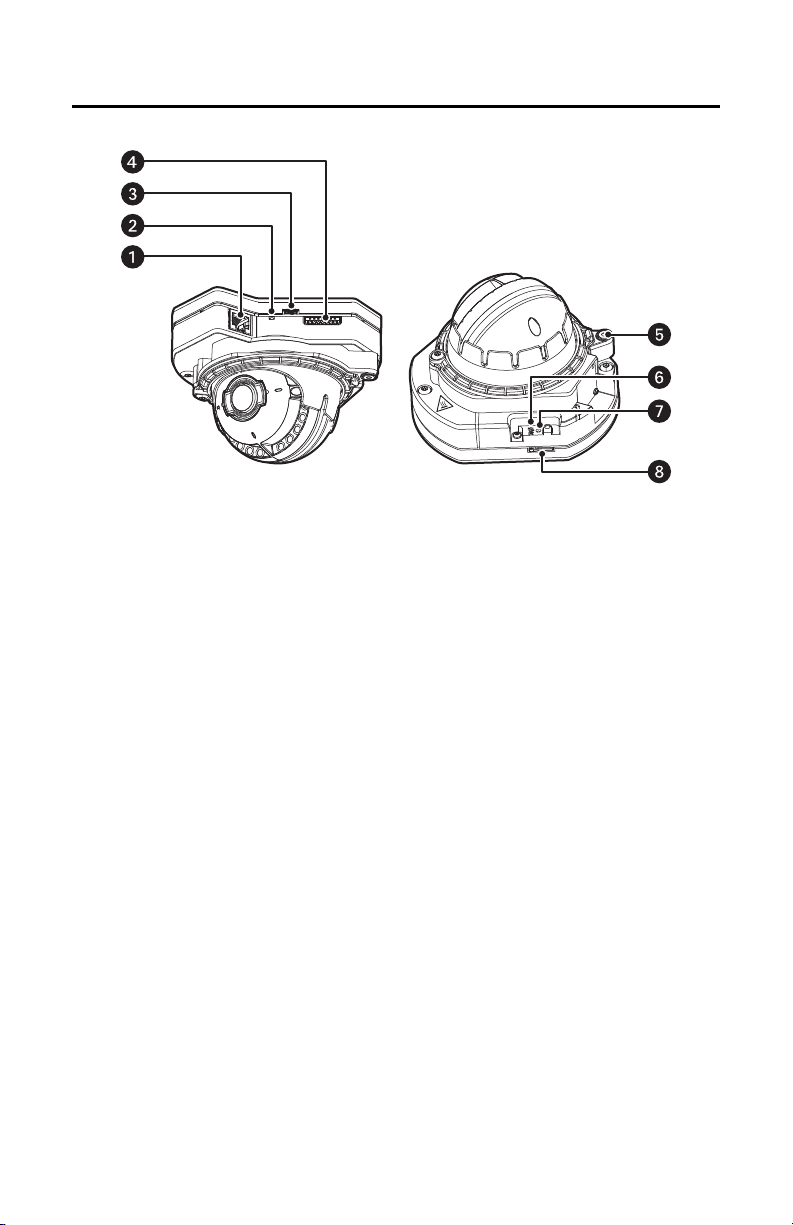
Product Overview
Figure 1. Camera Ports and LEDs
RJ-45 Network Port: Connects the camera to the IP network. Also supplies power to the camera (PoE),
ì
through the same connector.
Ethernet Activity/Link LED: Flashes green to indicate that data is being transmitted or received by the
î
camera. Glows solid amber to indicate that a live network connection is established.
ï
Accessory Port: Connects with compatible Pelco accessories.
ñ
Alarm/Relay/Audio Port: Connects to alarms, relays, and audio in/out.
ó
Microphone: Connects to built-in microphone on indoor and vandal-resistant models.
Reset Button: Reboots the camera or restores the camera’s factory default settings. This button is
r
recessed. Using a small tool, such as a paper clip, press and release the reset button once to reboot the
camera. Press and hold the reset button for 10 seconds to restore the camera to the factory default
settings.
Power LED: Flashes green during the configuration sequence; glows solid green after the sequence is
s
complete. The LED can be disabled. If this LED glows red (solid or flashing), contact Pelco Product Support
at 1-800-289-9100 (USA and Canada) or +1-559-292-1981 (international) for assistance.
t
Micro SD Slot: Connects to local storage.
For cable terminations, refer to Cable Terminations on page 41.
12 C2269M-A (11/13)
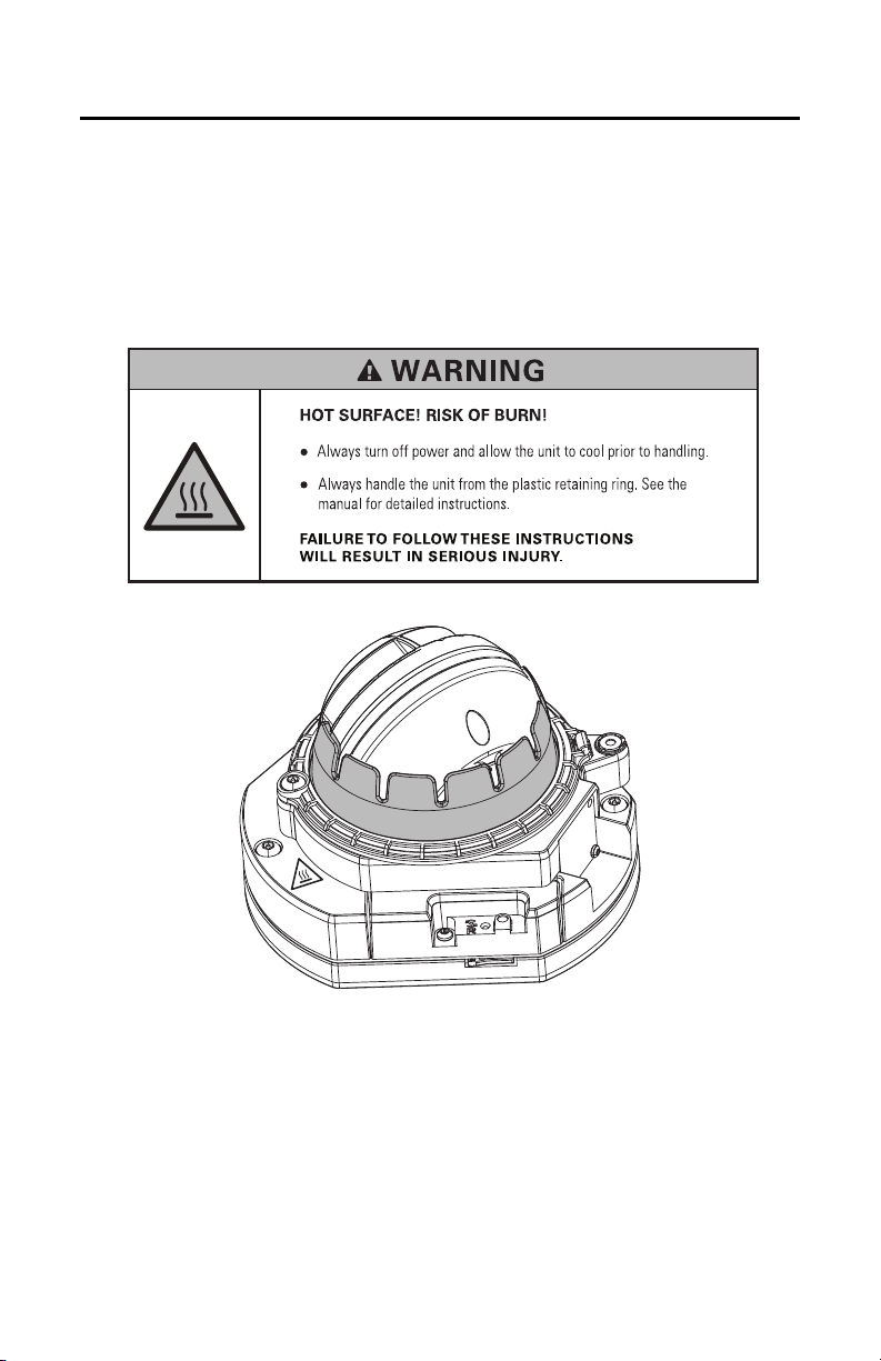
Installation
You can install the IME Series mini domes using one of the following methods:
• Installation in a suspended ceiling or a fixed ceiling. Refer to In-Ceiling: Indoor and Environmental/
Vandal-Resistant on page 14.
• Installation using a pendant mount. Refer to Pendant: Indoor on page 20 and Pendant:
Environmental/Vandal-Resistant on page 25.
• Installation on a wall or a fixed ceiling. Refer to Surface Mount: Indoor on page 30 and Surface
Mount: Environmental/Vandal-Resistant on page 35.
Figure 2. Plastic Retaining Ring
C2269M-A (11/13) 13
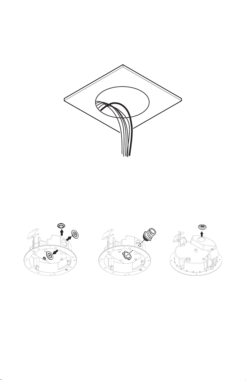
IN-CEILING: INDOOR AND ENVIRONMENTAL/VANDAL-RESISTANT
a. b1. b2.
1. Locate the center point of the mounting location in the ceiling.
2. For Environmental and Vandal-Resistant models, cut a 17.15 cm (6.75 in.) hole in the ceiling. For
Indoor models, cut a 15.24 cm (6.0 in.) hole in the ceiling. Using a hole saw is recommended.
3. Pull the wiring through the hole.
Figure 3. Cutting the Hole: In-Ceiling
4. Prepare the wire entry holes in the back box as follows:
a. Remove either the conduit plug (side) or grommet (top) for side or top wire entry.
b. Prepare the wire entry holes as follows:
(1) If using conduit (not supplied): Replace with 25 mm or 3/4 in. conduit adapters (not
supplied).
(2) If using the grommet (plenum rating is not required): Put the grommet (supplied)
aside for use in a later step.
Figure 4. Preparing the Cable Entry Holes: In-Ceiling
14 C2269M-A (11/13)
5. Install the back box as follows:
a. Compress the spring paddles on the back box. For Indoor models, make sure that the support
wings are rotated inward.
b. Push the back box through the hole.
c. Tighten the two mounting screws to secure the back box. For Indoor models, use the bit
(supplied).
d. Feed the wires as follows:
• If using conduit (not supplied): Feed wires through the conduit adapter, into the back
box, and attach the conduit to the adapter.
• If using the grommet (supplied): Feed the wires into the back box, pass the
unterminated cables through the grommet, and insert the grommet in either the side or
top entry.
e. Replace the other entry opening with the conduit plug (supplied).
f. Terminate the wires with the appropriate connector (not supplied).
Figure 5. Installing the Back Box: In-Ceiling
C2269M-A (11/13) 15

6. Connect the wiring to the camera as follows:
a. Connect the network cable to the RJ-45 network port on the base of the camera.
b. Connect the Micro USB cable and optional multiconductor cable as follows:
• If using a Pelco accessory: Perform step 5d on page 15 with the grommet and the
Micro B USB cable that is supplied with the Pelco accessory. Connect the Micro B USB
cable to the accessory port on the base of the camera.
NOTE: Remove this accessory before completing the installation.
• (Optional) If using alarms, relays, or audio: Connect a 24 AWG, 8-wire
multiconductor cable to the 8-pin removable connector (supplied), and then insert the
connector back into the base of the camera. This cable is for alarms, relays, and audio
line-in and line-out.
NOTE: For cable terminations, refer to Cable Terminations on page 41.
Figure 6. Connecting the Wiring: In-Ceiling
16 C2269M-A (11/13)

7. Install the camera as follows:
a. Align the camera inside the back box.
b. Tighten the two captive fasteners using the bit (supplied) until they are secure.
c. Dress the wires inside the back box.
Figure 7. Installing the Camera: In-Ceiling
8. Apply power to the camera. The camera will complete a configuration sequence. The LED at the
base of the camera will blink for several minutes while the camera system boots. The LED will turn
off when the system boot cycle completes.
NOTE: If the camera is not connected to a DHCP server and DHCP is enabled, the configuration
sequence might take several minutes to complete.
9. View the camera image by finding the camera’s IP address on a Web browser. If you do not know the
camera’s IP address, install the Pelco Device Utility software available at www.pelco.com. The
utility will locate the assigned name, IP address, and MAC address of the camera.
C2269M-A (11/13) 17

10. Adjust the camera field of view using the Web browser.
a. Loosen the locking screw with the bit (supplied).
b. Position the camera where desired.
c. Tighten the locking screw using the bit (supplied).
d. Use the Web browser to adjust the focus and zoom.
NOTICE: Risk of Wiring Damage! Do not continuously rotate the camera pan position beyond
360 degrees in a single direction. If you encounter resistance while turning, stop and rotate the
camera in the opposite direction. Failure to follow these instructions can result in equipment
damage.
Figure 8. Adjusting the Field of View: In-Ceiling
18 C2269M-A (11/13)

11. Install the lower dome as follows:
a. Align the screw holes on the trim ring with the holes on the back box.
b. For Environmental and Vandal-Resistant models, tighten the three tamperproof captive
fasteners using the bit (supplied) until the trim ring and bubble are secure. For Indoor models,
rotate the trim ring to lock it in place.
Figure 9. Installing the Lower Dome: In-Ceiling
C2269M-A (11/13) 19

PENDANT: INDOOR
1. Install the pendant mount (supplied) or the wall mount (not supplied).
The pendant mount attaches to 25 mm or 3/4 in. pipe/conduit (not supplied) through a pipe nipple
adapter (not supplied).
Figure 10. Installing the Pendant Mount: Indoor, Pendant
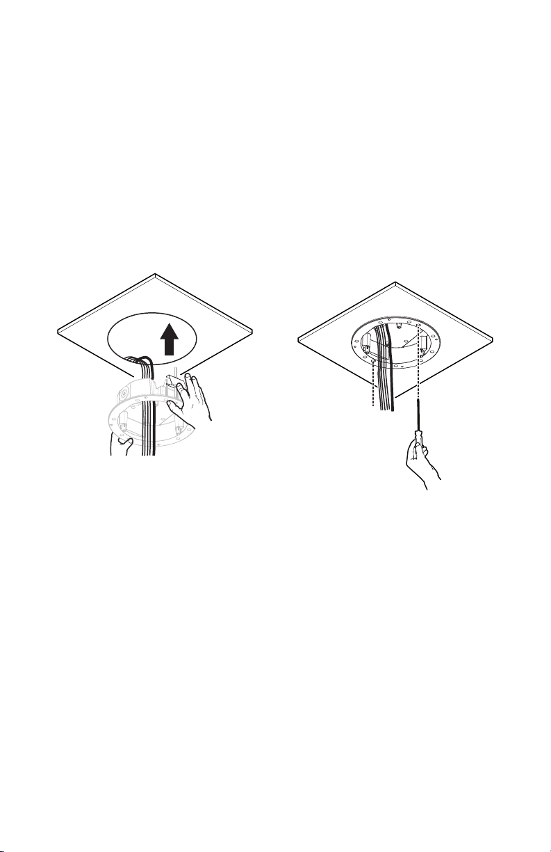
2. Pull the wiring through the opening in the pendant mount.
Figure 11. Pulling the Wiring: Indoor, Pendant
20 C2269M-A (11/13)

3. Connect the wiring to the camera as follows:
a. Connect the network cable to the RJ-45 network port on the base of the camera.
b. Connect the Micro USB cable and optional multiconductor cable as follows:
• If using a Pelco accessory: Perform step 5d on page 15 with the grommet and the
Micro B USB cable that is supplied with the Pelco accessory. Connect the Micro B USB
cable to the accessory port on the base of the camera.
NOTE: Remove this accessory before completing the installation.
• (Optional) If using alarms, relays, or audio: Connect a 24 AWG, 8-wire
multiconductor cable to the 8-pin removable connector (supplied), and then insert the
connector back into the base of the camera. This cable is for alarms, relays, and audio
line-in and line-out.
NOTE: For cable terminations, refer to Cable Terminations on page 41.
Figure 12. Connecting the Wiring: Indoor, Pendant
C2269M-A (11/13) 21

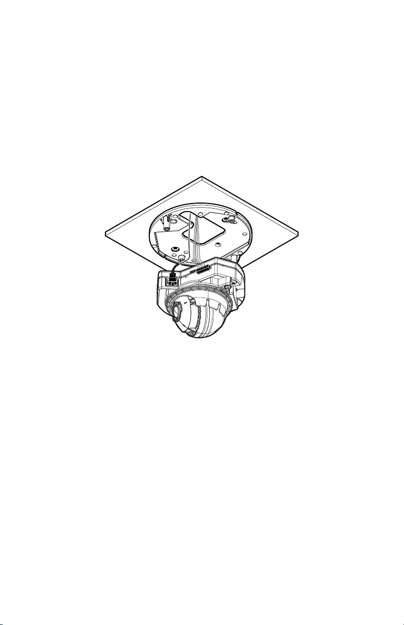
4. Install the camera as follows:
a. Align the camera with the pendant mount.
b. Tighten the two captive fasteners using the bit (supplied) until they are secure.
c. Dress the wires inside the pendant mount.
Figure 13. Installing the Camera: Indoor, Pendant
5. Apply power to the camera. The camera will complete a configuration sequence. The LED at the
base of the camera will blink for several minutes while the camera system boots. The LED will turn
off when the system boot cycle completes.
NOTE: If the camera is not connected to a DHCP server and DHCP is enabled, the configuration
sequence might take several minutes to complete.
6. View the camera image by finding the camera’s IP address on a Web browser. If you do not know the
camera’s IP address, install the Pelco Device Utility software available at www.pelco.com. The
utility will locate the assigned name, IP address, and MAC address of the camera.
22 C2269M-A (11/13)

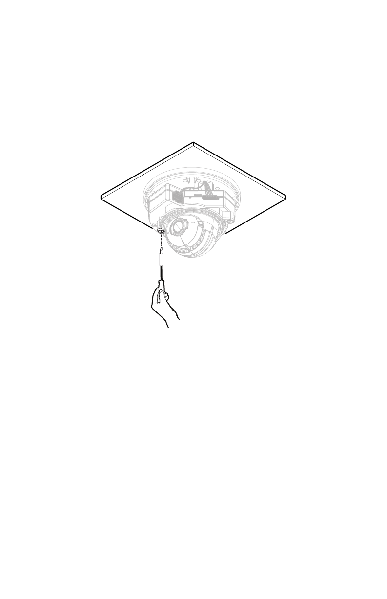
7. Adjust the camera field of view using the Web browser. (The unit must be powered.)
a. Loosen the locking screw with the bit (supplied).
b. Position the camera where desired.
c. Tighten the locking screw using the bit (supplied).
d. Use the Web browser to adjust the focus and zoom.
NOTICE: Risk of Wiring Damage! Do not continuously rotate the camera pan position beyond
360 degrees in a single direction. If you encounter resistance while turning, stop and rotate the
camera in the opposite direction. Failure to follow these instructions can result in equipment
damage.
Figure 14. Adjusting the Field of View: Indoor, Pendant
C2269M-A (11/13) 23

8. Install the lower dome to the pendant mount:
a. Align the screw holes on the trim ring with the holes on the mount.
b. Tighten the two tamperproof captive fasteners using the bit (supplied) until the trim ring and
bubble are secure.
Figure 15. Installing the Lower Dome: Indoor, Pendant
24 C2269M-A (11/13)

PENDANT: ENVIRONMENTAL/VANDAL-RESISTANT
1. Install the pendant mount to the conduit.
The pendant mount attaches to 1-1/2 in. NPT pipe/conduit or wall mount with 1-1/2 in. NPT thread
(not supplied).
Figure 16. Installing the Pendant Mount: Environmental/Vandal-Resistant, Pendant
2. Pull the wiring through the opening.
Figure 17. Pulling the Wiring: Environmental/Vandal-Resistant, Pendant
C2269M-A (11/13) 25

3. Connect the wiring to the camera as follows:
a. Connect the network cable to the RJ-45 network port on the base of the camera.
b. Connect the Micro USB cable and optional multiconductor cable as follows:
• If using a Pelco accessory: Perform step 5d on page 15 with the grommet and the
Micro B USB cable that is supplied with the Pelco accessory. Connect the Micro B USB
cable to the accessory port on the base of the camera.
NOTE: Remove this accessory before completing the installation.
• (Optional) If using alarms, relays, or audio: Connect a 24 AWG, 8-wire
multiconductor cable to the 8-pin removable connector (supplied), and then insert the
connector back into the base of the camera. This cable is for alarms, relays, and audio
line-in and line-out.
NOTE: For cable terminations, refer to Cable Terminations on page 41.
Figure 18. Connecting the Wiring: Environmental/Vandal-Resistant, Pendant
26 C2269M-A (11/13)

4. Install the camera as follows:
a. Align the camera with the pendant mount.
b. Tighten the two captive fasteners using the bit (supplied) until they are secure.
c. Dress the wires inside the pendant mount.
Figure 19. Installing the Camera: Environmental/Vandal-Resistant, Pendant
5. Apply power to the camera. The camera will complete a configuration sequence. The LED at the
base of the camera will blink for several minutes while the camera system boots. The LED will turn
off when the system boot cycle completes.
NOTE: If the camera is not connected to a DHCP server and DHCP is enabled, the configuration
sequence might take several minutes to complete.
6. View the camera image by finding the camera’s IP address on a Web browser. If you do not know the
camera’s IP address, install the Pelco Device Utility software available at www.pelco.com. The
utility will locate the assigned name, IP address, and MAC address of the camera.
C2269M-A (11/13) 27

7. Adjust the camera field of view using the Web browser. (The unit must be powered.)
a. Loosen the locking screw with the bit (supplied).
b. Position the camera where desired.
c. Tighten the locking screw using the bit (supplied).
d. Use the Web browser to adjust the focus and zoom.
NOTICE: Risk of Wiring Damage! Do not continuously rotate the camera pan position beyond
360 degrees in a single direction. If you encounter resistance while turning, stop and rotate the
camera in the opposite direction. Failure to follow these instructions can result in equipment
damage.
Figure 20. Adjusting the Field of View: Environmental/Vandal-Resistant, Pendant
28 C2269M-A (11/13)

8. Install the lower dome to the pendant mount:
a. Align the screw holes on the trim ring with the holes on the mount.
b. Tighten the three tamperproof captive fasteners using the bit (supplied) until the trim ring and
bubble are secure.
Figure 21. Installing the Lower Dome: Environmental/Vandal-Resistant, Pendant
C2269M-A (11/13) 29

SURFACE MOUNT: INDOOR
1. Refer to Surface Mount Templates on page 44 for a template to locate the holes to be drilled in the
mounting substrate.
2. Install the mounting plate to the mounting substrate using one of the following methods:
• Standard single-gang electrical box (not supplied)
• Any substrate using standard screw size M4 or #8 hardware (not supplied)
Figure 22. Fastening the Mounting Plate: Indoor, Surface Mount
3. Pull the wiring through the opening.
Figure 23. Pulling the Wiring: Indoor, Surface Mount
30 C2269M-A (11/13)
4. Connect the wiring to the camera as follows:
a. Connect the network cable to the RJ-45 network port on the base of the camera.
b. Connect the Micro USB cable and optional multiconductor cable as follows:
• If using a Pelco accessory: Perform step 5d on page 15 with the grommet and the
Micro B USB cable that is supplied with the Pelco accessory. Connect the Micro B USB
cable to the accessory port on the base of the camera.
NOTE: Remove this accessory before completing the installation.
• (Optional) If using alarms, relays, or audio: Connect a 24 AWG, 8-wire
multiconductor cable to the 8-pin removable connector (supplied), and then insert the
connector back into the base of the camera. This cable is for alarms, relays, and audio
line-in and line-out.
NOTE: For cable terminations, refer to Cable Terminations on page 41.
v
Figure 24. Connecting the Wiring: Indoor, Surface Mount
C2269M-A (11/13) 31

5. Install the camera as follows:
a. Align the camera with the mounting plate.
b. Tighten the two captive fasteners using the bit (supplied) until they are secure.
c. Dress the wires inside the mounting plate or gang box.
Figure 25. Installing the Camera: Indoor, Surface Mount
6. Apply power to the camera. The camera will complete a configuration sequence. The LED at the
base of the camera will blink for several minutes while the camera system boots. The LED will turn
off when the system boot cycle completes.
NOTE: If the camera is not connected to a DHCP server and DHCP is enabled, the configuration
sequence might take several minutes to complete.
7. View the camera image by finding the camera’s IP address on a Web browser. If you do not know the
camera’s IP address, install the Pelco Device Utility software available at www.pelco.com. The
utility will locate the assigned name, IP address, and MAC address of the camera.
32 C2269M-A (11/13)
8. Adjust the camera field of view using the Web browser. (The unit must be powered.)
a. Loosen the locking screw with the bit (supplied).
b. Position the camera where desired.
c. Tighten the locking screw using the bit (supplied).
d. Use the Web browser to adjust the focus and zoom.
NOTICE: Risk of Wiring Damage! Do not continuously rotate the camera pan position beyond
360 degrees in a single direction. If you encounter resistance while turning, stop and rotate the
camera in the opposite direction. Failure to follow these instructions can result in equipment
damage.
Figure 26. Adjusting the Field of View: Indoor, Surface Mount
C2269M-A (11/13) 33

9. Install the lower dome to the surface mount:
a. Align the screw holes on the trim ring with the holes on the mount.
b. Tighten the two tamperproof captive fasteners using the bit (supplied) until the trim ring and
bubble are secure.
Figure 27. Installing the Lower Dome: Indoor, Surface Mount
34 C2269M-A (11/13)

SURFACE MOUNT: ENVIRONMENTAL/VANDAL-RESISTANT
a. b1. b2.
1. Refer to Surface Mount Templates on page 44 for a template to locate the holes to be drilled in the
mounting substrate.
2. Install the mounting plate to the mounting substrate using one of the following methods:
• Standard 4 in. square electrical box (not supplied)
• Standard 2-gang electrical box (not supplied)
• Any substrate using standard screw size M6 or 1/4 in. hardware (not supplied)
NOTE: Head height and diameter of fasteners are not to exceed 5/16 in. and 3/4 in.,
respectively.
Figure 28. Fastening the Mounting Plate: Environmental/Vandal-Resistant, Surface Mount
3. Prepare the wire entry holes in the surface mounting ring as follows:
a. Remove either the conduit plug (side) or grommet (top) for side or top wire entry.
b. Prepare the wire entry holes as follows:
(1) If using conduit (not supplied): Insert a 25 mm or 3/4 in. conduit adapter
(not supplied).
(2) If using the grommet: Put the grommet (supplied) aside for use in a later step.
Figure 29. Preparing the Cable Entry Holes: Environmental/Vandal-Resistant, Surface Mount
C2269M-A (11/13) 35

4. Install the surface mounting ring to the mounting plate by tightening the three tamperproof captive
fasteners using the bit (supplied) until they are secure.
Figure 30. Installing the Surface Mounting Ring: Environmental/Vandal-Resistant, Surface Mount
5. Pull the wiring through the opening as follows:
• If using conduit (not supplied): Feed the wires through the conduit adapter (not supplied)
into the surface mounting ring, and attach the conduit to the adapter.
• If using the grommet: Feed the wires into the surface mounting ring, pass the unterminated
cables through the grommet, and insert the grommet in the top entry.
Figure 31. Pulling the Wiring: Environmental/Vandal-Resistant, Surface Mount
36 C2269M-A (11/13)

6. Connect the wiring to the camera as follows:
a. Connect the network cable to the RJ-45 network port on the base of the camera.
b. Connect the Micro USB cable and optional multiconductor cable as follows:
• If using a Pelco accessory: Perform step 5d on page 15 with the grommet and the
Micro B USB cable that is supplied with the Pelco accessory. Connect the Micro B USB
cable to the accessory port on the base of the camera.
NOTE: Remove this accessory before completing the installation.
• (Optional) If using alarms, relays, or audio: Connect a 24 AWG, 8-wire
multiconductor cable to the 8-pin removable connector (supplied), and then insert the
connector back into the base of the camera. This cable is for alarms, relays, and audio
line-in and line-out.
NOTE: For cable terminations, refer to Cable Terminations on page 41.
Figure 32. Connecting the Wiring: Environmental/Vandal-Resistant, Surface Mount
C2269M-A (11/13) 37

7. Install the camera as follows:
a. Align the camera inside the surface mount.
b. Tighten the two captive fasteners using the bit (supplied) until they are secure.
c. Dress the wires inside the surface mount.
Figure 33. Installing the Camera: Environmental/Vandal-Resistant, Surface Mount
8. Apply power to the camera. The camera will complete a configuration sequence. The LED at the
base of the camera will blink for several minutes while the camera system boots. The LED will turn
off when the system boot cycle completes.
NOTE: If the camera is not connected to a DHCP server and DHCP is enabled, the configuration
sequence might take several minutes to complete.
9. View the camera image by finding the camera’s IP address on a Web browser. If you do not know the
camera’s IP address, install the Pelco Device Utility software available at www.pelco.com. The
utility will locate the assigned name, IP address, and MAC address of the camera.
38 C2269M-A (11/13)

10. Adjust the camera field of view using the Web browser. (The unit must be powered.)
a. Loosen the locking screw with the bit (supplied).
b. Position the camera where desired.
c. Tighten the locking screw using the bit (supplied).
d. Use the Web browser to adjust the focus and zoom.
NOTICE: Risk of Wiring Damage! Do not continuously rotate the camera pan position beyond
360 degrees in a single direction. If you encounter resistance while turning, stop and rotate the
camera in the opposite direction. Failure to follow these instructions can result in equipment
damage.
Figure 34. Adjusting the Field of View: Environmental/Vandal-Resistant, Surface Mount
C2269M-A (11/13) 39

11. Install the lower dome to the surface mount:
a. Align the screw holes on the trim ring with the holes on the mount.
b. Tighten the three tamperproof captive fasteners using the bit (supplied) until the trim ring and
bubble are secure.
Figure 35. Installing the Lower Dome: Environmental/Vandal-Resistant, Surface Mount
40 C2269M-A (11/13)
Cable Terminations
1
2
3
4
5
6
7
8
1
2
3
4
5
6
7
8
8
8
1
1
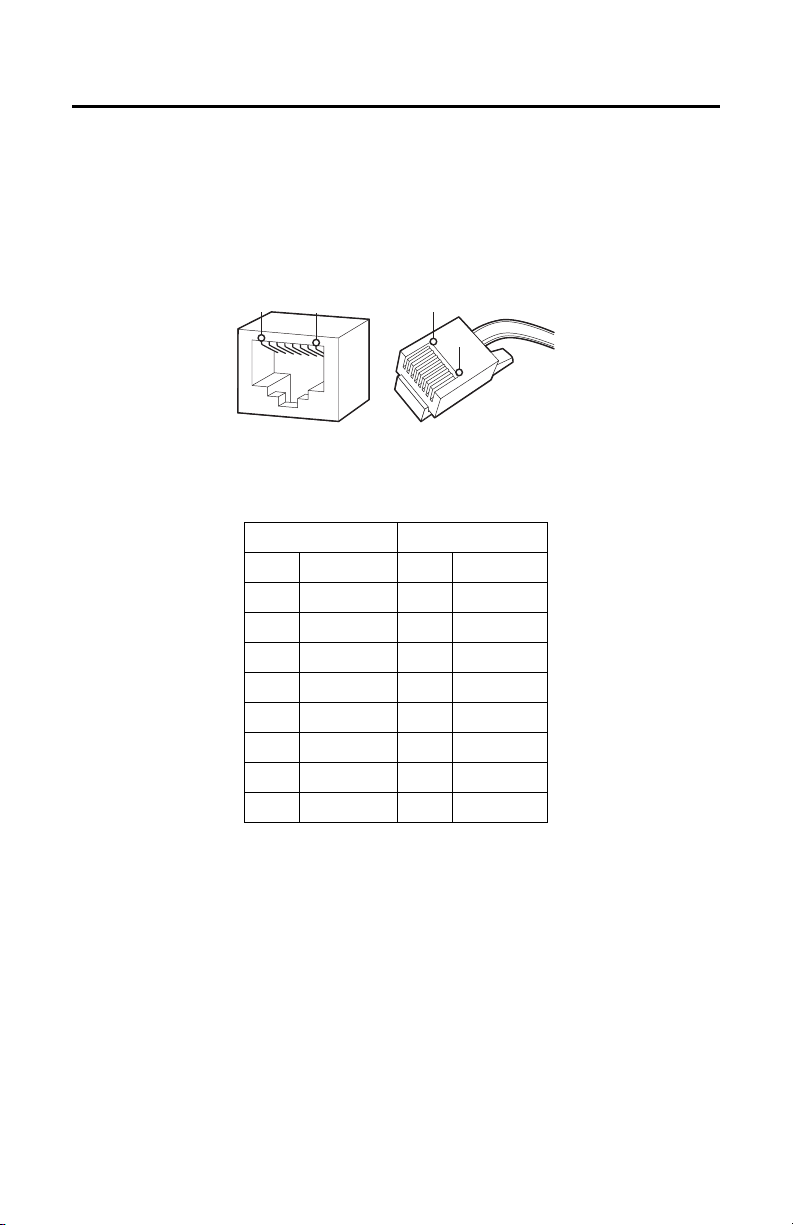
ETHERNET WIRING REQUIREMENT FOR POE
Connect a Cat5 cable or higher (Cat5e, Cat6) cable (not supplied) to the RJ-45 network connector. The 8-pin
port includes video over Ethernet, and PoE for the camera. PoE (IEEE 802.3af) injects power over the same
cabling that carries the network data, eliminating the need for a separate power supply. This simplifies the
installation and operation of the camera without affecting network performance.
NOTE: The camera will autosense and configure itself to use either a crossover cable or a straight cable.
Figure 36. Cable Pin Descriptions
Tab le A . Ethernet with PoE Modes A and B
PoE Mode A PoE Mode B
Pin Function Pin Function
1 TX+, PoE 1-2 1 TX+
2 TX–, PoE 1-2 2 TX–
3 RX+, PoE 3-4 3 RX+
4 Not used 4 PoE 1-2
5 Not used 5 PoE 1-2
6 RX–, PoE 3-4 6 RX–
7 Not used 7 PoE 3-4
8 Not used 8 PoE 3-4
C2269M-A (11/13) 41

ALARM/RELAY/AUDIO PORT
The 8-pin Alarm/Relay/Audio port has the following pins and pin assignments.
PIN 1 PIN 8
Figure 37. Alarm/Relay/Audio Port Pins
Tab le B . Pin Descriptions for Alarm/Relay/Audio Port
Pin Function
1 Audio Out–
2 Audio Out+
3 Audio In–
4 Audio In+
5 Alarm Input
6 Ground
7Relay N.O.
8 Relay Return
42 C2269M-A (11/13)

IP Address Settings
If the camera is connected to a Dynamic Host Configuration Protocol (DHCP) network and DHCP is set to
On, the server automatically assigns an IP address to the camera. The default setting for the camera is
DHCP On. To set the camera’s IP address manually, set DHCP to Off.
NOTES:
• If the camera is not connected to a DHCP server but DHCP is set to On, the default IP address
192.168.0.20 on subnet mask 255.255.255.0 is automatically assigned to the camera. After the first
camera is connected and assigned the default IP address, the system automatically looks for other
cameras on the auto IP address system and assigns IP addresses in sequential order as required.
• For example, if three cameras are connected to a network without a DHCP server, the first camera is
assigned address 192.168.0.20, the second camera is assigned address 192.168.0.21, and the third
camera is assigned address 192.168.0.22.
• Contact your network administrator to avoid network conflicts before setting/changing the camera’s
IP address.
• If you do not know the camera’s IP address, install the Pelco Device Utility software available at
www.pelco.com. The utility will locate the assigned name, IP address, and MAC address of the
camera.
Logging On to the Camera
After logging on to the camera, you can view video from the Web user interface.
1. Open the Web browser.
2. Type the camera’s IP address in the browser address bar.
NOTE: If you do not know the camera's IP address, you can locate it using the Pelco Device Utility
software.
3. Click the Log In button in the navigation bar; a dialog box opens.
4. Type your user name and password.
NOTE: If you are logging on to the camera as the administrator for the first time, the default user
name and password are admin (all lowercase). For security purposes, be sure to change the password
after you log on for the first time.
5. Click Log In.
C2269M-A (11/13) 43

Surface Mount Templates
Drill a 3/4 in. (minimum)
hole in this region.
NOTICE: Before printing this document, your printer must be set for 100% scaling. Printing the templates
at an incorrect scale could result in equipment damage.
NOTE: VALUES IN PARENTHESES ARE INCHES; ALL OTHERS ARE CENTIMETERS.
Figure 38. Template for Surface Mount: Indoor
44 C2269M-A (11/13)

Figure 39. Template for Surface Mount: Environmental/Vandal-Resistant
C2269M-A (11/13) 45

Specifications
CAMERA
Imaging Device 1/3-inch
Imager Type CMOS
Imager Readout Progressive scan
Highest Resolution
3 MPx 2048 x 1536
2 MPx 1920 x 1080
1 MPx 1280 x 1024
0.5 MPx 800 x 608
Signal-to-Noise Ratio >60 dB
Electronic Shutter Range 1 ~ 1/77,000 sec
True Wide Dynamic Range Up to 100 dB*
White Balance Range 2,000° to 10,000°K
Sensitivity 3 ~ 9 mm f/1.2; 2,850°K; SNR >20 dB
Color (33 ms) 0.1 lux
Color (500 ms) 0.005 lux
Mono (33 ms) 0.05 lux
Mono (500 ms) 0.0013 lux
Sensitivity 9 ~ 22 mm f/1.6; 2,850°K; SNR >20 dB
Color (33 ms) 0.4 lux
Color (500 ms) 0.009 lux
Mono (33 ms) 0.09 lux
Mono (500 ms) 0.002 lux
Day/Night Capabilities Yes
Mechanical IR Cut Filter Yes, (ON/OFF/AUTO selectable), with different set points on lux
*Sensor level is not inclusive of SureVision image processing.
LENS
Lens Type Built-in; varifocal
Focal Length f/1.2, 3 ~ 9 mm; or f/1.6, 9 ~ 22 mm
Focus Autofocus, motorized
Zoom Remote
Auto Iris Type DC drive P-iris lens
46 C2269M-A (11/13)

Field of View in Degrees
Lens
3 ~ 9 mm Wide 4:3 105 84 63
9 ~ 22 mm Wide 4:3 38 30 23
Focal
Length
Tele 4:3383023
Wide16:9978447
Tele 16:9353017
Tele 4:315128.9
Wide16:9353017
Tele 16:914126.6
Mode Diagonal Horizontal Vertical
ELECTRICAL
Network Port RJ-45 connector for 100Base-TX
Accessory Port Micro B USB connector for Pelco accessories
Cable Type Cat5 or better for 100Base-TX
Input Power PoE (IEEE 802.3af, Class 3)
Power Consumption* 8.5 W nominal
Current Consumption 350 mA maximum
Local Storage Micro SD
Alarm
Unsupervised Detects open or closed alarm state
Supervised Detects open and short alarm state with external 1-kohm resistor
Input 3.5 VDC maximum, 3.5 mA maximum
Relay Output ±32 VDC maximum, 150 mA maximum
*Does not include optional accessories connected to accessory port.
Auto MDI/MDI-X
AUDIO
Streaming Bidirectional: full or half duplex
Input/Output Line level/external microphone input;
Compression G.711 PCM 8 bit, 8 kHz mono at 64 kbit/s
600-ohm differential, 1 Vp-p max. signal level; built-in
microphone (indoor and vandal-resistant models)
MECHANICAL
Dome Attenuation
Clear f/0.0 light loss
Smoked f/1.0 light loss
Pan/Tilt Adjustment Manual
Pan 355°
Tilt 180°
Rotation 360°
C2269M-A (11/13) 47

ENVIRONMENTAL
Operating Temperature
Indoor/Vandal-Resistant –10° to 50°C (14° to 122°F)*
Environmental –40° to 50°C (–40° to 122°F)*
*Thermostatically controlled active heating and cooling elements are used to achieve operating
temperature range. A blower (fan) is used to achieve operating temperatures to 50°C (122°F). Active
heating elements are used to achieve operating temperatures below –10°C (14°F).
Cold Start
Indoor/Vandal-Resistant –10°C (14°F)
Environmental –20°C (–4°F)
Storage Temperature –10° to 60°C (14° to 140°F)
Operating Humidity
Indoor/Vandal-Resistant 20 to 80%, RH noncondensing
Environmental 10 to 95%, RH condensing
Storage Humidity 20 to 80%, RH noncondensing
Environmental/Vandal-Resistant
Impact Resistance K10++ (50 J) per IEC 62262
Shock and Vibration EN50155 Category 1, Class B; IEC 60068:2-6 and 2-27
(environmental/vandal-resistant models)
VIDEO
Video Streams Multiple simultaneous streams with up to 2 different
Available Resolutions 2 configurable streams as follows:
Camera Model
3 MPx 3.0 2048 1536 4:3 7 12 30 9.2
2 MPx 1.9 1600 1200 4:3 15 12 30 5.7
1 MPx 1.2 1280 960 4:3 30 12 30 3.8
0.5 MPx 0.5 800 608 4:3 30 7.8 30 2
3 MPx and 2 MPx 1080p 1920 1080 16:9 15 12 30 6
1 MPx 720p 1280 720 16:9 30 12 30 2.9
0.5 MPx 0.5 800 448 16:9 30 5.7 30 1.7
MPx Width Height
0.3 640 480 4:3 30 4.9 30 1.5
0.08 320 240 4:3 30 1.2 30 0.5
0.2 640 352 16:9 30 3.6 30 1.2
0.06 320 176 16:9 30 0.9 30 0.4
Frame Rate Up to 30, 25, 15, 12.5, 10, 5, 1 (depending on the coding,
Video Encoding H.264 High, Main, or Base profiles; and MJPEG
Bit Rate Control Constrained variable bit rate (CVBR), constant bit rate (CBR), and
Service Stream JPEG stream; the aspect ratio will be consistent with the
configurations plus service stream; the secondary stream is
variable based on the setup of the primary stream
Resolution JPEG H.264 High Profile
Aspect
Ratio
IPS
(Max.)
Recommended
Bit Rate
IPS
(Max.)
Recommended
Bit Rate
resolution, and stream configuration)
variable bit rate (VBR) with target range
independent streams
48 C2269M-A (11/13)

NETWORK
Supported Protocols TCP/IP, UDP/IP (Unicast, Multicast IGMP), UPnP, DNS, DHCP, RTP,
NOTE: IPv6 protocol supports mixed IPv4 and IPv6 installations, but not IPv6-only deployments.
Users
Unicast Up to 20 simultaneous users depending on the resolution settings
Multicast Unlimited users H.264
Security Access Password protected
Software Interface Web browser view and setup
RTSP, NTP, IPv4, IPv6, SNMP v2c/v3, QoS, HTTP, HTTPS, LDAP
(client), SSH, SSL, SMTP, FTP, ARP, ICMP, and 802.1x (EAP)
INTEGRATION
Pelco System Integration Endura 2.0 (or later);
Open API Pelco API or ONVIF Profile S
Mobile Application Integrated with Pelco Mobile Application
Digital Sentry 7.3 (or later);
DX4700/DX4800
PHYSICAL
Weight Unit
Indoor, In-Ceiling 1.2 kg (2.6 lb)
Indoor, Surface Mount 1.0 kg (2.0 lb)
Indoor, Pendant 1.0 kg (2.1 lb)
Environmental, In-Ceiling 1.4 kg (3.1 lb)
Environmental, Surface Mount 1.5 kg (3.3 lb)
Environmental, Pendant 1.3 kg (2.9 lb)
Vandal-Resistant, In-Ceiling 1.4 kg (3.1 lb)
Vandal-Resistant, Surface Mount 1.5 kg (3.3 lb)
Vandal-Resistant, Pendant 1.3 kg (2.9 lb)
C2269M-A (11/13) 49

NOTE: VALUES IN PARENTHESES ARE INCHES; ALL OTHERS ARE CENTIMETERS.
11.76
(4.63)
6.27
(2.47)
8.18 (3.22)
16.50 (6.50)
4.24
(1.67)
14.40
(5.67)
11.94
(4.70)
8.18
(3.22)
14.83
(5.84)
15.62 (6.15)
9.78 (3.85)
ENVIRONMENTAL/VANDAL-RESISTANT,
SURFACE MOUNT
INDOOR, IN-CEILING
INDOOR, SURFACE MOUNT
INDOOR, PENDANT
ENVIRONMENTAL/VANDAL-RESISTANT, IN-CEILING
19.18 (7.55)
12.54
(4.94)
5.64
(2.22)
7.44
(2.93)
3.61
(1.42)
9.78 (3.85)
ENVIRONMENTAL/VANDAL-RESISTANT, PENDANT
14.35
(5.65)
8.18
(3.22)
15.80 (6.22)
10.08
(3.97)
9.78 (3.85)
11.74
(4.62)
50 C2269M-A (11/13)

REVISION HISTORY
Manual # Date Comments
C2269M 7/13 Original version.
C2269M-A 11/13 Updated dome and alarm pin images. Caution and introductory text added. Revised
Pelco, the Pelco logo, and other trademarks a ssociated with Pelco products referred to in this publication are trademarks of P elco, Inc. or its affiliates.
All other product names and services are th e property of their respective companies. ONVIF and the ONVIF logo are trademarks of ONVIF Inc.
Product specifications and availability are subject to change without notice. © Copyright 2013, Pelco, Inc. All rights re served.
Specifications and Installation sections. New back box and trim ring for Indoor, In-Ceiling
models.

Pelco by Schneider Electric 3500 Pelco Way Clovis, California 93612-5699 United States
USA & Canada Tel (800) 289-9100 Fax (800) 289-9150
International Tel +1 (559) 292-1981 Fax +1 (559) 348-1120
www.pelco.com www.pelco.com/community
 Loading...