

Page 1
INSTALLATION MANUAL
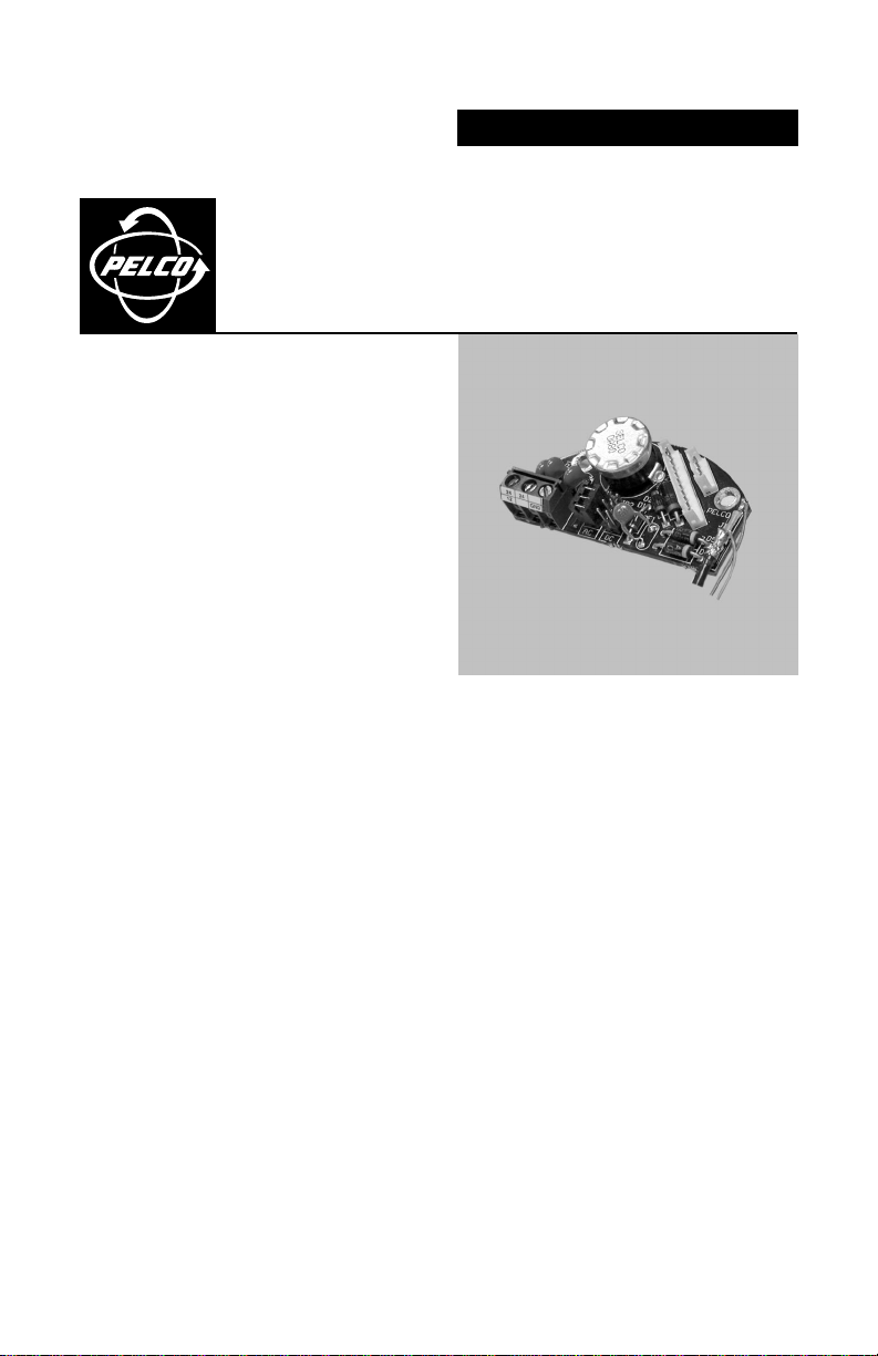
PC Board Retrofit Kit for
®
ICS100 and ICS150
ICS-KITRETRO
C2405M (8/02)
Page 2

INTRODUCTION
Previous models of the ICS100/ICS150 back box are not compatible with the latest Camclosure
™
camera module. To install the camera module, use the ICS-KITRETRO kit and modify the back box.
There are two methods of installation:
• The video coaxial cable is accessible and can be pulled into the back box. Refer to
page 3 for installation instructions.
• The video coaxial cable is not accessible and cannot be pulled into the back box.
Refer to page 4 for installation instructions.
2 C2405M (8/02)
Page 3
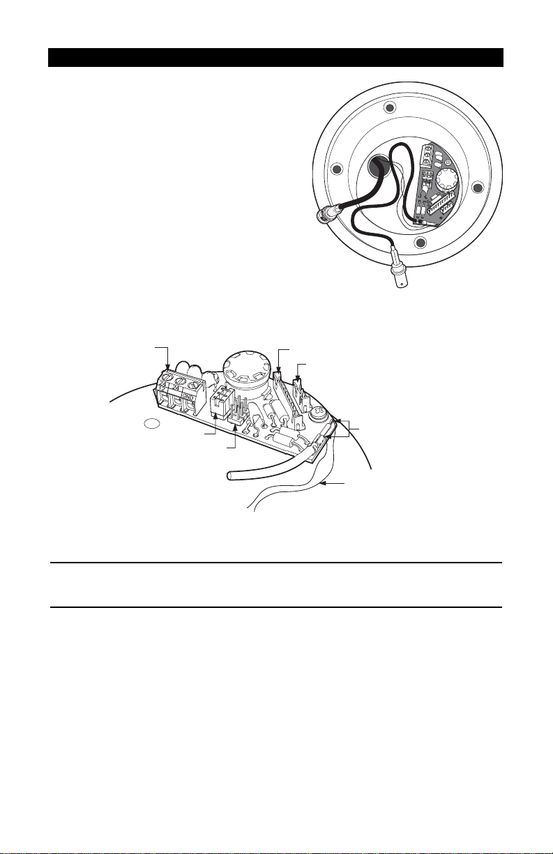
CABLE IS ACCESSIBLE
POWER
TERMINAL
24 VAC JUMPER
12 VDC JUMPER
VIDEO CONNECTOR
HEATER CONNECTOR
NOTE: CUT WIRES HERE
BLOCK CONNECTOR WIRES
Turn off power to the ICS100/ICS150.
Remove the lower dome and camera module.
Remove the PC board from the base of the
unit.
Pull the video coaxial cable into the back box.
Install the new board inside the back box.
Note: The block connector attached to the
new PC board is not required for this
installation. Either push the connector into
the conduit or completely remove it. To
remove the connector cut the wires attached
to the board. Cut the wires as close to the
board as possible so that they do not
interfere with the operation of the unit.
Connect the BNC video connector to the mating BNC connector.
CAUTION: The camera is set for 24 VAC operation at the factory. For 12 VDC operation remove the
jumper from the 24 VAC position and install it on the 12 VDC position.
Connect the input power wires to the new board.
24 VAC: Connect the wires to the two blocks labeled 24.
12 VDC: Connect the wires to the blocks labeled 12 and GND. Move the jumper to the 12 VDC
position.
Connect the camera video and heater connectors to the board. Plug the video connector from
the camera into the mating connector on the board. If the heater is installed, plug the heater
connector from the camera into the mating connector.
Install the camera. Gently squeeze the camera bracket, place it against the shoulder inside the
base, and then gently release.
C2405M (8/02) 3
Page 4

CABLE IS NOT ACCESSIBLE
Turn off power to the ICS100/ICS150. Remove the lower dome and camera module. Remove
the PC board from the base of the back box. Do not discard the screws.
Reposition the board and attach it to the base using one of the screws removed in step 1.
4 C2405M (8/02)
Page 5

ICS100 Installation
ICS150 Installation
Install the new board inside the back box.
Note: The BNC connector attached to the board is not required for the installation. Either push
the video cable into the conduit or cut the cable and remove it. Cut the cable as close to the
board as possible so that it will not interfere with the operation of the unit.
Connect the input power wires to the new board.
24 VAC: Connect the wires to the two blocks labeled 24.
12 VDC: Connect the wires to the blocks labeled 12 and GND. Move the jumper to the 12 VDC
position.
Plug the block male connector attached to the new board into the female video connector of
the old board. Connect power, video, and heater.
C2405M (8/02) 5
Page 6

POWER TERMINAL
VIDEO CONNECTOR
MALE CONNECTOR
FROM NEW BOARD
FEMALE VIDEO
CONNECTOR
(OLD BOARD)
24 VAC JUMPER
VIDEO CONNECTOR
HEATER
CONNECTOR
HEATER
CONNECTOR
Connect the camera video and heater connectors to the board. Plug the video connector from
the camera into the mating connector on the board. If the heater is installed, plug the heater
connector from the camera into the mating connector.
Install the camera. Gently squeeze the camera bracket, place it against the shoulder inside the
base, and then gently release.
6 C2405M (8/02)
Page 7

WARRANTY AND RETURN INFORMATION
WARRANTY
Pelco will repair or replace, without charge, any merchandise proved defective in material or workmanship for a period of one year after the date of
shipment. Exceptions to this warranty are as noted below:
• Five years on Pelco manufactured cameras (CC3500/CC3600/CC3700 and MC3500/MC3600 Series); two years on all other cameras.
• Three years on Genex® Series (multiplexers, server, and keyboard).
•Two years on all standard motorized or fixed focal length lenses.
•Two years on Legacy®, Camclosure™ Camera Systems, CM6700/CM6800/CM8500/CM9500/CM9740/CM9760 Matrix, DF5 and DF8 Series Fixed
Dome products.
•Two years on Spectra®, Esprit™, and PS20 Scanners, including when used in continuous motion applications.
•Two years on Esprit and WW5700 series window wiper (excluding wiper blades).
• Eighteen months on DX Series digital video recorders.
• One year (except video heads) on video cassette recorders (VCRs). Video heads will be covered for a period of six months.
• Six months on all pan and tilts, scanners or preset lenses used in continuous motion applications (that is, preset scan, tour and auto scan modes).
Pelco will warrant all replacement parts and repairs for 90 days from the date of Pelco shipment. All goods requiring warranty repair shall be sent
freight prepaid to Pelco, Clovis, California. Repairs made necessary by reason of misuse, alteration, normal wear, or accident are not covered under
this warranty.
Pelco assumes no risk and shall be subject to no liability for damages or loss resulting from the specific use or application made of the Products.
Pelco’s liability for any claim, whether based on breach of contract, negligence, infringement of any rights of any party or product liability, relating to
the Products shall not exceed the price paid by the Dealer to Pelco for such Products. In no event will Pelco be liable for any special, incidental or
consequential damages (including loss of use, loss of profit and claims of third parties) however caused, whether by the negligence of Pelco or
otherwise.
The above warranty provides the Dealer with specific legal rights. The Dealer may also have additional rights, which are subject to variation from
state to state.
If a warranty repair is required, the Dealer must contact Pelco at (800) 289-9100 or (559) 292-1981 to obtain a Repair Authorization number (RA), and
provide the following information:
1. Model and serial number
2. Date of shipment, P.O. number, Sales Order number, or Pelco invoice number
3. Details of the defect or problem
If there is a dispute regarding the warranty of a product which does not fall under the warranty conditions stated above, please include a written
explanation with the product when returned.
Method of return shipment shall be the same or equal to the method by which the item was received by Pelco.
RETURNS
In order to expedite parts returned to the factory for repair or credit, please call the factory at (800) 289-9100 or (559) 292-1981 to obtain an
authorization number (CA number if returned for credit, and RA number if returned for repair).
All merchandise returned for credit may be subject to a 20% restocking and refurbishing charge.
Goods returned for repair or credit should be clearly identified with the assigned CA or RA number and freight should be prepaid. Ship to the
appropriate address below.
If you are located within the continental U.S., Alaska, Hawaii or
Puerto Rico:
Service Department
Pelco
3500 Pelco Way
Clovis, CA 93612-5699
If you are located outside the continental U.S., Alaska, Hawaii or Puerto Rico:
Intermediate Consignee Ultimate Consignee
American Overseas Air Freight Pelco
320 Beach Road 3500 Pelco Way
Burlingame, CA 94010 Clovis, CA 93612-5699
USA USA
® Pelco, the Pelco logo, Spectra, Genex, Coaxitron, and Legacy are registered trademarks of Pelco.
™ Esprit and Camclosure are trademarks of Pelco.
© Copyright 2002, Pelco. All rights reserved.
REVISION HISTORY
Manual # Date Comments
C2405M 8/02 Original version.
C2405M (8/02) 7
Page 8

®
World Headquarters
3500 Pelco Way
Clovis, California 93612 USA
USA & Canada
Tel: 800/289-9100
Fax: 800/289-9150
International
Tel: 1-559/292-1981
Fax: 1-559/348-1120
www.pelco.com
ISO9001
Orangeburg, New York Las Vegas, Nevada Eindhoven, The Netherlands Wokingham, United Kingdom Montreal, Canada
 Loading...