

Page 1
INSTALLATION
ICS110-CW Series
Camclosure
Integrated Camera System
Wide Dynamic Range (WDR)
®
C3406M-D (1/07)
Page 2

Page 3

Contents
Regulatory Notices . . . . . . . . . . . . . . . . . . . . . . . . . . . . . . . . . . . . . . . . . . . . . . . . . . . . . . . . . . . . . . . . 5
Description . . . . . . . . . . . . . . . . . . . . . . . . . . . . . . . . . . . . . . . . . . . . . . . . . . . . . . . . . . . . . . . . . . . . . . 6
Models . . . . . . . . . . . . . . . . . . . . . . . . . . . . . . . . . . . . . . . . . . . . . . . . . . . . . . . . . . . . . . . . . . . . 6
Cover and Back Box Installation. . . . . . . . . . . . . . . . . . . . . . . . . . . . . . . . . . . . . . . . . . . . . . . . . . . . . . 8
Unshielded Twisted Pair (UTP) Video . . . . . . . . . . . . . . . . . . . . . . . . . . . . . . . . . . . . . . . . . . . . . 8
Basic Surface Installation . . . . . . . . . . . . . . . . . . . . . . . . . . . . . . . . . . . . . . . . . . . . . . . . . . . . . . 8
4S Electrical Box Installation . . . . . . . . . . . . . . . . . . . . . . . . . . . . . . . . . . . . . . . . . . . . . . . . . . . 9
404 Plaster Ring Installation. . . . . . . . . . . . . . . . . . . . . . . . . . . . . . . . . . . . . . . . . . . . . . . . . . . 11
Side Conduit Installation . . . . . . . . . . . . . . . . . . . . . . . . . . . . . . . . . . . . . . . . . . . . . . . . . . . . . 12
Camera Module . . . . . . . . . . . . . . . . . . . . . . . . . . . . . . . . . . . . . . . . . . . . . . . . . . . . . . . . . . . . . . . . . 14
Module Removal . . . . . . . . . . . . . . . . . . . . . . . . . . . . . . . . . . . . . . . . . . . . . . . . . . . . . . . . . . . . 14
Camera Orientation. . . . . . . . . . . . . . . . . . . . . . . . . . . . . . . . . . . . . . . . . . . . . . . . . . . . . . . . . . 16
Module Installation. . . . . . . . . . . . . . . . . . . . . . . . . . . . . . . . . . . . . . . . . . . . . . . . . . . . . . . . . . 16
Camera Adjustments . . . . . . . . . . . . . . . . . . . . . . . . . . . . . . . . . . . . . . . . . . . . . . . . . . . . . . . . . . . . . 17
Varifocal Lens Zoom and Focus Adjustments. . . . . . . . . . . . . . . . . . . . . . . . . . . . . . . . . . . . . . 17
Switch Settings. . . . . . . . . . . . . . . . . . . . . . . . . . . . . . . . . . . . . . . . . . . . . . . . . . . . . . . . . . . . . 18
Vertical Phase Adjustment (24 VAC Operation Only) . . . . . . . . . . . . . . . . . . . . . . . . . . . . . . . . 19
Adjusting the Vertical Phase . . . . . . . . . . . . . . . . . . . . . . . . . . . . . . . . . . . . . . . . . . . . . . 19
Camera Positioning . . . . . . . . . . . . . . . . . . . . . . . . . . . . . . . . . . . . . . . . . . . . . . . . . . . . . . . . . . . . . . 20
Install Dome and Trim Ring . . . . . . . . . . . . . . . . . . . . . . . . . . . . . . . . . . . . . . . . . . . . . . . . . . . . . . . . 21
Service Connector . . . . . . . . . . . . . . . . . . . . . . . . . . . . . . . . . . . . . . . . . . . . . . . . . . . . . . . . . . . . . . . 22
Specifications . . . . . . . . . . . . . . . . . . . . . . . . . . . . . . . . . . . . . . . . . . . . . . . . . . . . . . . . . . . . . . . . . . . 24
C3406M-D (1/07) 3
Page 4

List of Illustrations
1 Package Components . . . . . . . . . . . . . . . . . . . . . . . . . . . . . . . . . . . . . . . . . . . . . . . . . . . . . 7
2 Basic Surface Installation. . . . . . . . . . . . . . . . . . . . . . . . . . . . . . . . . . . . . . . . . . . . . . . . . . 9
3 4S Electrical Box Installation . . . . . . . . . . . . . . . . . . . . . . . . . . . . . . . . . . . . . . . . . . . . . . 10
4 404 Plaster Ring Installation. . . . . . . . . . . . . . . . . . . . . . . . . . . . . . . . . . . . . . . . . . . . . . . 12
5 Side Conduit Installation . . . . . . . . . . . . . . . . . . . . . . . . . . . . . . . . . . . . . . . . . . . . . . . . . 13
6 Camera Module Bracket . . . . . . . . . . . . . . . . . . . . . . . . . . . . . . . . . . . . . . . . . . . . . . . . . . 14
7 Back Box Connectors . . . . . . . . . . . . . . . . . . . . . . . . . . . . . . . . . . . . . . . . . . . . . . . . . . . . 15
8 Camera Orientation. . . . . . . . . . . . . . . . . . . . . . . . . . . . . . . . . . . . . . . . . . . . . . . . . . . . . . 16
9 Location of Zoom and Focus Adjustments . . . . . . . . . . . . . . . . . . . . . . . . . . . . . . . . . . . . 17
10 DIP Switch. . . . . . . . . . . . . . . . . . . . . . . . . . . . . . . . . . . . . . . . . . . . . . . . . . . . . . . . . . . . . 18
11 Vertical Phase Adjustment . . . . . . . . . . . . . . . . . . . . . . . . . . . . . . . . . . . . . . . . . . . . . . . . 19
12 Positioning the Camera. . . . . . . . . . . . . . . . . . . . . . . . . . . . . . . . . . . . . . . . . . . . . . . . . . . 20
13 Dome Liner Adjustment . . . . . . . . . . . . . . . . . . . . . . . . . . . . . . . . . . . . . . . . . . . . . . . . . . 21
14 Service Connector. . . . . . . . . . . . . . . . . . . . . . . . . . . . . . . . . . . . . . . . . . . . . . . . . . . . . . . 22
15 Attaching the 2.5 mm Monaural Headphone Plug . . . . . . . . . . . . . . . . . . . . . . . . . . . . . . 23
4 C3406M-D (1/07)
Page 5

Regulatory Notices
This device complies with Part 15 of the FCC Rules. Operation is subject to the following two
conditions: (1) this device may not cause harmful interference, and (2) this device must accept any
interference received, including interference that may cause undesired operation.
RADIO AND TELEVISION INTERFERENCE
This equipment has been tested and found to comply with the limits of a Class B digital device,
pursuant to Part 15 of the FCC Rules. These limits are designed to provide reasonable protection
against harmful interference in a residential installation. This equipment generates, uses, and can
radiate radio frequency energy and, if not installed and used in accordance with the instructions, may
cause harmful interference to radio communications. However there is no guarantee that the
interference will not occur in a particular installation. If this equipment does cause harmful
interference to radio or television reception, which can be determined by turning the equipment off
and on, the user is encouraged to try to correct the interference by one or more of the following
measures:
•
Reorient or relocate the receiving antenna.
•
Increase the separation between the equipment and the receiver.
•
Connect the equipment into an outlet on a circuit different from that to which the receiver is
connected.
•
Consult the dealer or an experienced radio/TV technician for help.
You may also find helpful the following booklet, prepared by the FCC: “How to Identify and Resolve
Radio-TV Interference Problems.” This booklet is available from the U.S. Government Printing Offi ce,
Washington D.C. 20402.
Changes and modifications not expressly approved by the manufacturer or registrant of this
equipment can void your authority to operate this equipment under Federal Communications
Commission’s rules.
This Class B digital apparatus complies with Canadian ICES-003.
Cet appareil numérique de la classe B est conforme à la norme NMB-003 du Canada.
The materials used in the manufacture of this document and its components are compliant to the
requirements of Directive 2002/95/EC.
This equipment contains electrical or electronic components that must be recycled properly to
comply with Directive 2002/96/EC of the European Union regarding the disposal of waste electrical
and electronic equipment (WEEE). Contact your local dealer for procedures for recycling this
equipment.
C3406M-D (1/07) 5
Page 6

Description
The ICS110-CW Series Camclosure® integrated camera system combines an environmental cover,
back box, camera, lens, and lower dome into a small, high-security system that is quick and easy to
install. The system is perfect for a variety of indoor and outdoor applications and its versatile design
allows for multiple mounting options.
The ICS110-CW Series Camclosure integrated camera system can be installed directly to a ceiling,
wall, 4S electrical box (using the optional ICS110-AP adapter plate), or a standard plaster ring.
The system has three conduit openings: two in the base and a threaded 0.75-inch (1.91 cm) opening
in the side.
Before installing your new system, thoroughly familiarize yourself with the information in this
manual.
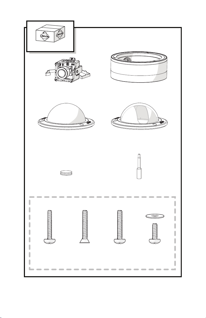
The following is supplied with the ICS110-CW Series Camclosure integrated camera system:
Qty Description
1 ICS110-CW Series Camclosure integrated camera system
• Cover and back box (assembled)
• Trim ring with bubble; clear bubble models include a dome liner
• Camera module
1 Black plug
1 1/8-inch hollow screwdriver bit
2 8-32 x 0.375-inch Phillips pan head screws with washers (attached to cover and back box)
3 6-32 x 0.75-inch Phillips pan head screws
2 8-32 x 0.75-inch Phillips flat head screws
2 8-32 x 0.75-inch Phillips pan head screws
MODELS
ICS110-CW-V39 Indoor/outdoor dome, vandal resistant, surface mount, smoked bubble, gray
ICS111-CW-V39 Indoor/outdoor dome, vandal resistant, surface mount, clear bubble, gray
6 C3406M-D (1/07)
finish, 3-9 mm varifocal lens with DC-drive auto iris
finish, 3-9 mm varifocal lens with DC-drive auto iris
Page 7
SHIPPING BOX
CAMERA MODULE
(1)
TRIM RING AND
SMOKED BUBBLE
(1)
BLACK PLUG
(1)
SHOWN ACTUAL SIZE
< OR >
COVER AND
BACK BOX (1)
TRIM RING, DOME LINER,
AND CLEAR BUBBLE
(1)
1/8-INCH HOLLOW
SCREWDRIVER BIT (1)
6-32 X 0.75-INCH
PHILLIPS PAN HEAD
SCREWS (3)
8-32 X 0.75-INCH
PHILLIPS FLAT HEAD
SCREWS (2)
Figure 1.
C3406M-D (1/07) 7
8-32 X 0.75-INCH
PHILLIPS PAN HEAD
SCREWS (2)
Package Components
8-32 X 0.375-INCH
PHILLIPS PAN HEAD
SCREWS WITH
WASHERS (2 EACH)
Page 8

Cover and Back Box Installation
The ICS110-CW Series Camclosure integrated camera system mounts only to a surface. It can be
wired through the cover into a surface, electrical box, or plaster ring. You can also wire it through a
side conduit.
UNSHIELDED TWISTED PAIR (UTP) VIDEO
The ICS110-CW Series offers support for unshielded twisted pair (UTP). The UTP video output signal
is 1 Vp-p differential into a 100-ohm load. The unit uses active UTP.
At a minimum, UTP requires Cat5, 100-ohm twisted pair cable. The maximum UTP wiring distance is
3,000 ft (914 m).
BASIC SURFACE INSTALLATION
NOTE:
You should install the camera module into the back box before installing the back box into the
cover. When installing the back box into the cover, rotate the camera module to access the mounting
holes. Refer to
1. Remove the two 8-32 x 0.375-inch Phillips pan head screws and washers to separate the
2. Using the cover as a template, mark one of the large holes on the mounting surface.
3. Cut out the hole for the power and video wiring.
4. Pull the video and power wires through the hole in the cover.
5. Attach the cover to the mounting surface (hardware not supplied). Use stainless steel
6. Connect the video cable/wires:
7. Connect the power wires.
Camera Module
cover from the back box.
hardware when installing the system outdoors.
BNC:
Connect the BNC connector from the unit to a mating BNC connector.
Twisted Pair (UTP):
Voltage Red Wire Black Wire
12 VDC + Ground
24 VAC ~ ~
on page 14 for more information.
Blue wire = Video +
Gray wire = Video -
AC operation only:
the same transformer, connect one side of the transformer to the red wire on all units, and
connect the other side of the transformer to the black wire on all units. Failure to connect all of
the units the same way will cause the cameras to be out of phase with each other and may
produce a vertical roll when switching between cameras.
8 C3406M-D (1/07)
If you are wiring more than one Camclosure integrated camera system to
Page 9
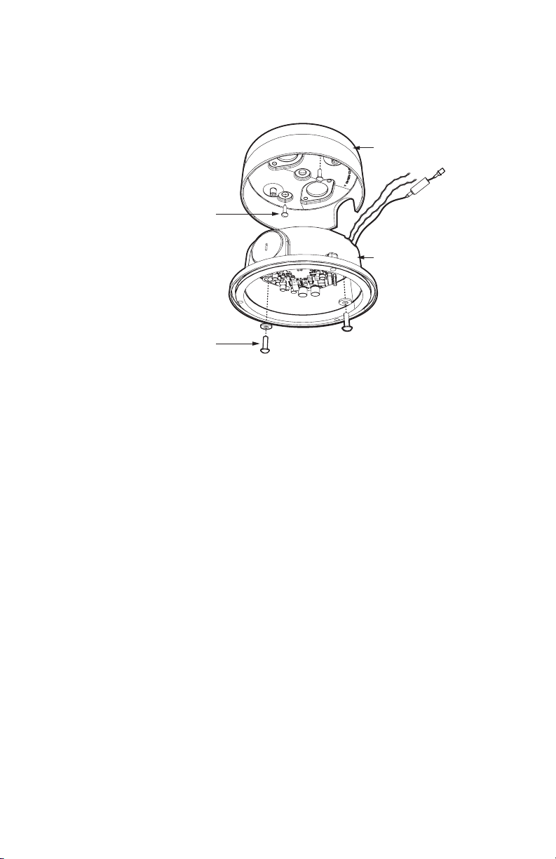
8. Reinstall the back box inside the cover. For vandal-resistant installations, rotate the back box
to position the conduit plug opposite the notch on the side of the cover. Use the two
8-32 x 0.375-inch Phillips pan head screws and washers (removed earlier) to secure the back
box to the cover.
COVER
MOUNTING
SCREWS
(NOT SUPPLIED)
BACK BOX
8-32 X 0.375-INCH
PHILLIPS PAN HEAD
SCREWS WITH WASHERS
(SUPPLIED)
Figure 2.
Basic Surface Installation
4S ELECTRICAL BOX INSTALLATION
NOTE:
You should install the camera module into the back box before installing the back box into the
cover. When installing the back box into the cover, rotate the camera module to access the mounting
holes. Refer to
1. Attach an ICS110-AP adapter plate (not supplied) to a 4S box. Use two 8-32 x 0.75-inch
2. Remove the two 8-32 x 0.375-inch Phillips pan head screws and washers to separate the
3. Pull the video and power wires into the cover.
4. Attach the cover to the adapter plate with up to four 8-32 x 0.375-inch Phillips pan head
5. Connect the video cable/wires:
Camera Module
for more information.
Phillips flat head screws (supplied with both the ICS110 and the adapter plate).
cover from the back box.
screws (supplied with the adapter plate). Use stainless steel hardware when installing the
system outdoors.
BNC:
Connect the BNC connector from the unit to a mating BNC connector.
Twisted Pair (UTP):
Blue wire = Video +
Gray wire = Video -
C3406M-D (1/07) 9
Page 10

6. Connect the power wires.
Voltage Red Wire Black Wire
12 VDC + Ground
24 VAC ~ ~
AC operation only:
If you are wiring more than one Camclosure integrated camera system to
the same transformer, connect one side of the transformer to the red wire on all units, and
connect the other side of the transformer to the black wire on all units. Failure to connect all of
the units the same way will cause the cameras to be out of phase with each other and may
produce a vertical roll when switching between cameras.
7. Reinstall the back box inside the cover. For vandal-resistant installations, rotate the back box
to position the conduit plug opposite the notch on the side of the cover. Use the two
8-32 x 0.375-inch Phillips pan head screws and washers (removed earlier) to secure the back
box to the cover.
4S STANDARD
ELECTRICAL BOX
CEILING/
WALL
8-32 X 0.75-INCH
PHILLIPS FLAT
HEAD SCREWS
(SUPPLIED)
ADAPTER PLATE
(ICS110-AP)
COVER
8-32 X 0.375-INCH
PHILLIPS PAN
HEAD SCREWS
(SUPPLIED WITH
ICS110-AP)
BACK BOX
8-32 X 0.375-INCH
PHILLIPS PAN HEAD
SCREWS WITH WASHERS
10 C3406M-D (1/07)
(SUPPLIED)
Figure 3.
4S Electrical Box Installation
Page 11

404 PLASTER RING INSTALLATION
NOTE:
You should install the camera module into the back box before installing the back box into the
cover. When installing the back box into the cover, rotate the camera module to access the mounting
holes. Refer to
1. Remove the two 8-32 x 0.375-inch Phillips pan head screws and washers to separate the
2. Pull video and power wires into the cover. Use up to three supplied 6-32 x 0.75-inch Phillips
3. Connect the video cable/wires:
4. Connect the power wires.
Camera Module
cover from the back box.
pan head screws or two supplied 8-32 x 0.75-inch Phillips pan head screws to attach the cover
to an installed 404 plaster ring. Use stainless steel hardware when installing the system
outdoors.
BNC:
Connect the BNC connector from the unit to a mating BNC connector.
Twisted Pair (UTP):
Voltage Red Wire Black Wire
12 VDC + Ground
24 VAC ~ ~
on page 14 for more information.
Blue wire = Video +
Gray wire = Video -
AC operation only:
the same transformer, connect one side of the transformer to the red wire on all units, and
connect the other side of the transformer to the black wire on all units. Failure to connect all of
the units the same way will cause the cameras to be out of phase with each other and may
produce a vertical roll when switching between cameras.
If you are wiring more than one Camclosure integrated camera system to
C3406M-D (1/07) 11
Page 12

5. Reinstall the back box inside the cover. For vandal-resistant installations, rotate the back box
to position the conduit plug opposite the notch on the side of the cover. Use the two
8-32 x 0.375-inch Phillips pan head screws and washers (removed earlier) to secure the back
box to the cover.
CEILING/
WALL
404 PLASTER RING
(NOT SUPPLIED)
COVER
6-32 X 0.75-INCH
OR 8-32 X 0.75-INCH
PHILLIPS PAN
HEAD SCREWS
(SUPPLIED)
BACK BOX
8-32 X 0.375-INCH
PHILLIPS PAN HEAD
SCREWS WITH WASHERS
(SUPPLIED)
Figure 4.
404 Plaster Ring Installation
SIDE CONDUIT INSTALLATION
NOTE:
You should install the camera module into the back box before installing the back box into the
cover. When installing the back box into the cover, rotate the camera module to access the mounting
holes. Refer to
1. Remove the two 8-32 x 0.375-inch Phillips pan head screws and washers to separate the
2. Attach the cover to the mounting surface (hardware not supplied). Use stainless steel
3. Remove the conduit plug from the side of the back box.
4. Use a blunt tool to pull the wires and plug, located on the base of the back box, into the back
5. Insert the black plug (supplied) into the hole in the base of the back box.
6. Reinstall the back box inside the cover. Line up the conduit plug with the notch on the side of
12 C3406M-D (1/07)
Camera Module
on page 14 for more information.
cover from the back box.
hardware when installing the system outdoors.
box.
the cover. Use the two 8-32 x 0.375-inch Phillips pan head screws and washers (removed
earlier) to secure the back box to the cover.
Page 13

7. Install a 0.75-inch (1.91 cm) threaded conduit connector (not supplied) into the conduit hole in
the back box.
COVER
0.75-INCH CONDUIT
CONNECTOR
BACK BOX
REMOVE
CONDUIT PLUG
8-32 X 0.375-INCH
PHILLIPS PAN HEAD
SCREWS WITH WASHERS
(SUPPLIED)
Figure 5.
Side Conduit Installation
8. Connect the video cable/wires:
BNC:
Connect the BNC connector from the unit to a mating BNC connector.
Twisted Pair (UTP):
Blue wire = Video +
Gray wire = Video -
9. Connect the power wires.
Voltage Red Wire Black Wire
12 VDC + Ground
24 VAC ~ ~
AC operation only:
If you are wiring more than one Camclosure integrated camera system to
the same transformer, connect one side of the transformer to the red wire on all units, and
connect the other side of the transformer to the black wire on all units. Failure to connect all of
the units the same way will cause the cameras to be out of phase with each other and may
produce a vertical roll when switching between cameras.
C3406M-D (1/07) 13
Page 14

Camera Module
The ICS110-CW Series Camclosure camera module includes the camera, camera bracket, and heater
board. To perform most camera adjustments, you must remove the module from the back box.
Use the following instructions to remove and reinstall the camera module.
WARNING:
adjusting the camera. This applies to all models.
Heater elements could be hot! When camera power is on, use caution when
MODULE REMOVAL
To remove the camera module from the back box:
1. Gently squeeze the bracket and pull the module out of the back box (refer to Figure 6).
Figure 6.
Camera Module Bracket
BRACKET
14 C3406M-D (1/07)
Page 15

2. Unplug the camera (10-pin), heater board (four-pin), and service (three-pin) connectors from
the back box (refer to Figure 7).
HEATER BOARD CONNECTOR
SERVICE
CONNECTOR
CAMERA
CONNECTOR
Figure 7.
Back Box Connectors
C3406M-D (1/07) 15
Page 16

CAMERA ORIENTATION
At the factory, the camera module is configured for ceiling mounting. For wall mounting, you must
change the camera orientation or the video image will be upside down.
To change the camera orientation (refer to Figure 8):
1. Remove the camera module from the back box if necessary.
2. Remove the tilt adjustment screw and lock washer from each side of the camera.
3. Carefully rotate the camera one half turn. Make sure the wiring harness does not bind.
4. Reinstall the tilt adjustment screw and lock washer on each side of the camera.
5. Verify the camera orientation.
CEILING MOUNT (DEFAULT) WALL MOUNT
BOTTOM
OF CAMERA
TOP OF
CAMERA
TILT ADJUSTMENT
SCREW AND
LOCK WASHER
Figure 8.
TILT ADJUSTMENT
SCREW AND
LOCK WASHER
Camera Orientation
MODULE INSTALLATION
To install the camera module into the back box:
1. Plug the camera (10-pin), heater board (four-pin), and service (three-pin) connectors into the
back box (refer to Figure 7 on page 15).
2. Make sure the tabs on the camera bracket and the service connector are pointing out of the
enclosure, away from the ceiling or wall.
3. Gently squeeze the bracket, place it against the groove inside back box, and gently release
(refer to Figure 6 on page 14).
16 C3406M-D (1/07)
Page 17

Camera Adjustments
To perform the following camera adjustments, make sure to plug in the camera and service
connectors. You may have to remove the camera module from the back box.
Connect a monitor. Then turn on power to the camera and monitor. To use the service connector, refer
Service Connector
to
To adjust the DIP switches or the vertical phase, you will need a miniature trimpot adjustment tool
with a 0.05-inch (1.27 mm) blade. Suggested tools include a miniature fl at-tip screwdriver, a Philmore
trimpot tool (#63-6808), and the Philmore 10-piece tool set (#63-910).
After you have adjusted the unit, reinstall the camera module into the back box, and install the trim
ring, bubble, and dome liner (if necessary).
NOTES:
•
The electronics of the ICS110-CW automatically adjust the camera to the auto iris. Auto iris
level adjustments are not necessary.
•
The R7 adjustment is reserved.
VARIFOCAL LENS ZOOM AND FOCUS ADJUSTMENTS
To adjust the field of view and the focus:
1. Select a field of view by turning the zoom adjustment ring clockwise/counterclockwise (refer
to Figure 9).
2. Tighten the zoom locking screw.
3. Adjust the focus by moving the focus locking screw clockwise/counterclockwise.
4. Tighten the focus locking screw.
on page 22.
FOCUS
ZOOM
Figure 9.
C3406M-D (1/07) 17
Location of Zoom and Focus Adjustments
Page 18

SWITCH SETTINGS
Locate the DIP switch (refer to Figure 10). Then set the switches for your installation.
DIP SWITCH
DOWN UP
123456
ON
SWITCH POSITION
Figure 10.
DIP Switch
SW1: Video Format
Set to ON for NTSC. Set to OFF for PAL. The default is ON.
SW2: Line Sync
Set to ON to use AC line lock. Set to OFF for internal line sync. The default is ON.
SW3: Interlaced Scanning/Progressive Scanning
Set to ON to select interlaced scanning. Set to OFF to select progressive scanning. The default is ON.
SW4: Auto White Balance (AWB)/Auto Tracking White Balance (ATW)
Set to ON to enable ATW. This is the default.
To manually set and lock the white balance (AWB), power up the unit. Then place a white background
in front of the lens and turn SW4 to OFF.
SW5/SW6: Profile
Select the preset profile that best matches your installation:
Profile
Minimum
Illumination
SW5 SW6
General (default) 6.0 lux ON ON
Extended shutter 0.5 lux (15 fps) OFF ON
Extended dynamic range 3.0 lux ON OFF
Fluorescent 3.0 lux OFF OFF
General (default):
Extended shutter:
Use for most installations. This profile provides very good general image quality.
Use for installation that are mostly low light.
18 C3406M-D (1/07)
Page 19

Extended dynamic range:
entrances, and exits. This profile offers the maximum wide dynamic range.
Fluorescent:
NOTE:
Use for any installation with flickering lighting of any kind.
If you select the Fluorescent profile, you should enable AC line lock for best results.
Use for extremely high dynamic installations, for example, doorways,
VERTICAL PHASE ADJUSTMENT (24 VAC OPERATION ONLY)
When using more than one camera power supply, a brief vertical roll may occur on the monitor when
switching from one camera to another.
To eliminate vertical roll, reverse the 24 VAC connections on one camera. If both cameras are
connected to the same transformer, this should solve the problem. If the problem still exists, adjust
the phase control by synchronizing, or line-locking, the cameras to one another.
ADJUSTING THE VERTICAL PHASE
You may need two people when synchronizing the cameras: one at the camera, the other at the
monitor to observe the vertical roll and the effect of any camera adjustments.
To synchronize the cameras:
1. Choose a reference camera to which all other cameras will be phased.
2. Select the camera to synchronize. Use the phase adjustment control (R8) to synchronize the
camera to the reference camera (refer to Figure 11). Turn R8 clockwise to increase vertical
phase; turn R8 counterclockwise to decrease vertical phase.
3. Each time an adjustment is made, switch back and forth between the camera you are
adjusting and the reference camera. Repeat this process as many times as necessary until the
roll between the cameras is no longer noticeable.
4. Adjust the phase of all other cameras by repeating steps 2 through 3. Always adjust to the
reference camera selected in step 1.
NOTE:
The preferred method for camera phase adjustment is to use a dual trace oscilloscope to
align the vertical sync pulses of the reference camera to the selected camera(s).
R8 R7 (RESERVED)
Figure 11.
C3406M-D (1/07) 19
Vertical Phase Adjustment
Page 20

Camera Positioning
Manually rotate and tilt the camera module to position the camera. Then tighten the tilt screws (axis
in Figure 12).
NOTE:
Do not over-rotate the module. Excessively turning the module in one direction could result
in damage to the wiring.
Tilt 140° (20°-160°) Pan 360° Rotation 360°
Figure 12.
Positioning the Camera
20 C3406M-D (1/07)
Page 21

Install Dome and Trim Ring
1. Adjust the dome liner if installed (refer to Figure 13):
a. Align the screw holes in the trim ring with those in the back box to identify the proper
dome liner position.
b. Loosen the three Phillips screws located in the trim ring.
c. Insert the blade of a standard screwdriver in one of the adjustment grooves. Rotate the
dome liner to position the viewing window over the camera lens.
d. Tighten the three Phillips screws to lock the dome liner in place.
ADJUSTMENT
GROOVE
DOME LINER
LOOSEN SCREWS
Figure 13.
2. Align the screw holes in the trim ring with those in the back box.
3. Tighten the tamper-resistant screws through the trim ring into the back box. Use the supplied
1/8-inch hollow screwdriver bit.
C3406M-D (1/07) 21
Dome Liner Adjustment
Page 22

Service Connector
The ICS110-CW Series Camclosure integrated camera system includes a service connector that
outputs camera video. Use it at the installation site to set up the field of view and focus the camera.
SERVICE
CONNECTOR
Figure 14.
Pelco offers two optional items that plug directly into the service connector. Before using either
option, you must loosen the tamper-resistant screws to remove the trim ring from the back box. Use
the supplied 1/8-inch hollow screwdriver bit.
The CST150 has a 3-foot (0.9 m) cable and microdisplay for viewing camera video. Plug it into the
service connector and view the video.
NOTE:
The three buttons on the CST150 are not used with the ICS110-CW.
The ICS090-SC has a 4-foot (1.2 m) cable with a service connector and a BNC connector. Plug the
service connector into the unit. Then connect the other end to any standard BNC (VIDEO IN) connector
on a monitor.
Service Connector
22 C3406M-D (1/07)
Page 23

To assemble a longer service cable for the Camclosure integrated camera system, purchase the
following from a local electronics supply store:
1 2.5 mm monaural headphone plug
1 CPM 88 miniature coaxial connector
1 RG174/U coaxial cable
To assemble the cable:
1. Attach the CPM 88 miniature coaxial connector to one end of the cable. Follow the directions
supplied with the miniature coaxial connector.
2. Attach the 2.5 mm monaural plug to the other end of the coaxial cable (refer to Figure 15):
a. Remove the support sleeve from the plug.
b. Slip the support sleeve over the end of the cable.
c. Prepare the cable.
d. Solder the center connector of the cable to the center pin of the plug.
e. Thread the braid of the cable through the hole in the crimp pin.
f. Solder the braid to the top of the crimp pin.
g. Crimp the end of the crimp pin around the cable.
h. Reassemble the support sleeve and the plug.
CENTER CONDUCTOR
COAXIAL
CABLE
Figure 15.
C3406M-D (1/07) 23
BRAID (SHIELD)
Attaching the 2.5 mm Monaural Headphone Plug
2.5 mm MONAURAL
HEADPHONE PLUG
Page 24

Specifications
CAMERA
Imaging Device 1/3-inch imager
Dynamic Range 102 dB typical/120 dB maximum
Picture Elements Sensor resolution: 742 (H) x 552 (V)
Signal System NTSC or PAL
Scanning System 2:1 interlace/progressive
Synchronization Internal/AC line lock
Horizontal Resolution More than 504 TV lines
Iris Control Auto
Electronic Shutter Range Auto (1/15 - 1/22,000)
Auto Iris Lens Type DC-drive
Minimum Illumination 0.5 lux, F1.2, 40 IRE, AGC on, 75% scene reflectance
Signal-to-Noise Ratio >53 dB
Vertical Phase Adjustable ±200˚
Gain Control Auto (36 dB maximum)
Backlight Compensation Auto
Signal Processing Digital Signal Processing (DSP)
Video Output Composite: 1 Vp-p, 75 ohms
Auto White Balance Auto or manual (switch selectable); 2700˚K to 7500˚K
LENS
Type Varifocal
Format Size 1/3-inch
Focal Length 3 ~ 9 mm
Zoom Ratio 3X
Relative Aperture (F) 1.2 ~ 2.1
Operation
Iris Auto (DC-drive)
Focus Manual
Zoom Manual
Angle of View*
Diagonal 118.7˚ to 41.5˚
Horizontal 92.8˚ to 33.3˚
Vertical 68.8˚ to 25˚
Minimum Object Distance 1.64 ft (0.5 m)
Back Focal Length 6.1 ~ 12 mm
(extended shutter mode, 15 fps)
UTP: Active 1 Vp-p, 100 ohms
*Focal length specifications presume a 10% horizontal and 4% vertical monitor overscan.
24 C3406M-D (1/07)
Page 25

BACKBOX
Electrical
Input Voltage** 12 VDC or 24 VAC (±10%), autosensing
Power Consumption 10 watts or less
Video Connector Composite: BNC
UTP: Twisted pair
General
Pan/Tilt Adjustment Manual
Pan 360°
Tilt 80° (20° to 100° range)
Rotation 360°
Construction Aluminum with steel camera mounting bracket and polycarbonate
Finish Gray polyester powder coat
Environment Low temperature, indoor/outdoor
Cable Entry 3/4-inch (1.91 cm) conduit fitting and 3/4-inch (1.91 cm) opening for
Operating Temperature -50° to 122°F (-46° to 50°C)
Unit Weight 2.2 lb (1.0 kg)
**24 VAC power is recommended when installing any Camclosure Integrated Camera System under
fluorescent lighting conditions.
dome
NPT threaded pipe
De-ices to 25°F (-4°C)
(Design and product specifications subject to change without notice.)
3X Ø .343
THRU
2.36
3.593
(9.136)
1.797
(5.026)
NOTE: VALUES IN PARENTHESES ARE CENTIMETERS;
ALL OTHERS ARE IN INCHES.
C3406M-D (1/07) 25
(6.00)
5.50
(13.97)
1.76
(4.47)
4.01
(10.19)
3.79
(9.63)
Page 26

26 C3406M-D (1/07)
Page 27

PRODUCT WARRANTY AND RETURN INFORMATION
WARRANTY
Pelco will repair or replace, without charge, an y merchandise proved defective in material or workmanship for a period of one year after the date of
shipment.
Exceptions to this warranty are as noted below:
• Five years on FR/FT/FS Series fiber optic products and TW3000 Series unshielded twisted pair transmission products.
• Three years on Spectra® IV products.
• Three years on Genex® Series products (multiplexers, server, and keyboard).
• Three years on Camclosure® and fixed camera models, except the CC3701H-2, CC3701H-2X, CC3751H-2, CC3651H-2X, MC3651H-2, and
MC3651H-2X camera models, which h ave a five-year warranty.
• Three years on PMCL200/300/400 Series LCD mon itors.
• Two years on standard motorized or fixed focal length lenses.
• Two years on Legacy®, CM6700/CM6800/CM9700 Series matrix, and DF5/DF8 Series fixed dome products.
• Two years on Spectra III™, Esprit®, ExSite™, and PS20 scanners, including when used in continuous motion applications.
• Two years on Esprit and WW5700 Series window wiper (excluding wiper blades).
• Two years (except lamp and color wheel) on Digital Light Processing (DLP®) displays. The lamp and color wheel will be covered for a period of
90 days. The air filter is not covered un der warranty.
• Eighteen months on DX Series digital video recorders, NVR300 Series network video recorders, and Endura™ Series distributed network-based video
products.
• One year (except video heads) on video cassette recorders (VCRs). Video heads will be covered for a period of six months.
• Six months on all pan and tilts, scanners or pr eset lenses used in continuous motion applications (that is, preset scan, tour and auto scan mode s).
Pelco will warrant all replacement par ts and repairs for 90 days from the date of Pelco shipment. All goods requiring warranty repair shall be sent freight
prepaid to Pelco, Clovis, California. Repairs made necessary by reason of misuse, alteration, normal wear, or accident are not covered under this
warranty.
Pelco assumes no risk and shall be subject to no liability for damages or loss resulting from the sp ecific use or application made of the Products. Pelco’s
liability for any claim, whether based on breach of contract, negligence, infringement of an y rights of any party or product liability, relating to the Products
shall not exceed the price paid by the Dealer to Pelco for such Products. In no event will Pelco be liable for any special, incidental or consequential
damages (including loss of use, loss of prof it and claims of third parties) however caused, whether by the negligence of Pelco or otherwise.
The above warranty provides the Dealer with spe cific legal rights. The Dealer may also have additional rights, which are subject to variation from state
to state.
If a warranty repair is required, the Dealer must contact Pelco at (800) 289-9100 or (559) 292-1981 to obtain a Repair Authorization number (RA), and
provide the following information:
1. Model and serial number
2. Date of shipment, P.O. number, Sales Order number, or Pelco invoice number
3. Details of the defect or problem
If there is a dispute regarding the warranty of a p roduct which does not fall under the warranty conditions stated above, pleas e include a written
explanation with the product when returned.
Method of return shipment shall be the sam e or equal to the method by which the item was received by Pelco.
RETURNS
In order to expedite parts returned to the factory for repair or credit, plea se call the factory at (800) 289-9100 or (559) 292-1981 to obtain an autho rization
number (CA number if returned for credit, and RA number if returned for repair).
All merchandise returned for credit may be sub ject to a 20% restocking and refurbishing charge.
Goods returned for repair or credit should be clearly identified with the assigned CA or RA number and freigh t should be prepaid. Ship to the appropriate
address below.
If you are located within the continental U.S., Alaska, Hawaii or Puerto Rico, send goods to:
Service Department
Pelco
3500 Pelco Way
Clovis, CA 93612-5699
If you are located outside the continental U.S., Alaska, Hawaii or Puerto Rico and are instructed to return goods to the USA, you may do one of the
following:
If the goods are to be sent by a COURIER SERVICE, send the go ods to:
Pelco
3500 Pelco Way
Clovis, CA 93612-5699 USA
If the goods are to be sent by a FREIGHT FORWARDER, send the good s to:
Pelco c/o Expeditors
473 Eccles Avenue
South San Francisco, CA 94080 USA
Phone: 650-737-1700
Fax: 650-737-0933
REVISION HISTORY
Manual # Date Comments
C3406M 4/06 Original version.
C3406M-A 6/06 Added note to install camera module into back box before installation (ECO 06-13656).
C3406M-B 6/06 Updated DIP switch profile settings.
C3406M-C 7/06 Removed auto iris adjustment procedure.
C3406M-D 1/07 Updated figure 11. Described unused auto iris adjustment.
Pelco, the Pelco logo, Camclosure, Esprit, Genex, Legacy, and Spectra are registered trademarks of Pelco. ©Copyright 2007, Pelco.
Endura and ExSite are trademarks of Pelco. All rights reserved.
DLP is a registered trademark of Texas Instruments, Inc.
Page 28

Worldwide Headquarters
3500 Pelco Way
Clovis, California 93612 USA
USA & Canada
Tel: 800/289-9100
Fax: 800/289-9150
International
Tel: 1-559/292-1981
Fax: 1-559/348-1120
www.pelco.com
ISO9001
Australia
Canada | Finland | France | Italy | Russia | Singapore | Spain | Sweden
|
The Netherlands
| United Arab Emirates | United Kingdom | United States
 Loading...