

Page 1
®
ICI3016/ICI3008
16- and 8-Position
®
Inter-Check
Switchers
Installation and Operation
Manual C1007M-B (2/96)
1.0 WARNINGS
Prior to installation and use of this product, the following
WARNINGS should be observed.
1. Installation and servicing should only be done by
Qualified Service Personnel and conform to all
Local codes. Only use replacement parts
recommended by PELCO.
2 After replacement/repair of this unit’s electrical
components, conduct a resistance measurement
between line and exposed parts to verify the exposed
parts have not been connected to line circuitry.
NOTE: Familiarize yourself with the information in this manual prior to installation and
operation. Contact the customer's dealer/installer prior to installation and operation. Some
warranties and/or service agreements may be
affected.
2.0 SCOPE
This manual covers the installation and operation of the
Inter-Check® ICI3008 and ICI3016 switchers.
2.1 DESCRIPTION
The Inter-Check® ICI3008 and ICI3016 are alarming, sequential video switchers designed to be used exclusively
with the Inter-Check® ICI3000P Point of Sale (POS) monitoring systems.
Pelco • 3500 Pelco Way, Clovis, CA 93612-5699 • (559) 292-1981 • (800) 289-9100
FAX (800) 289-9150 or (559) 292-3827
Page 2

3.0 INSTALLATION
4.0 PROGRAMMING
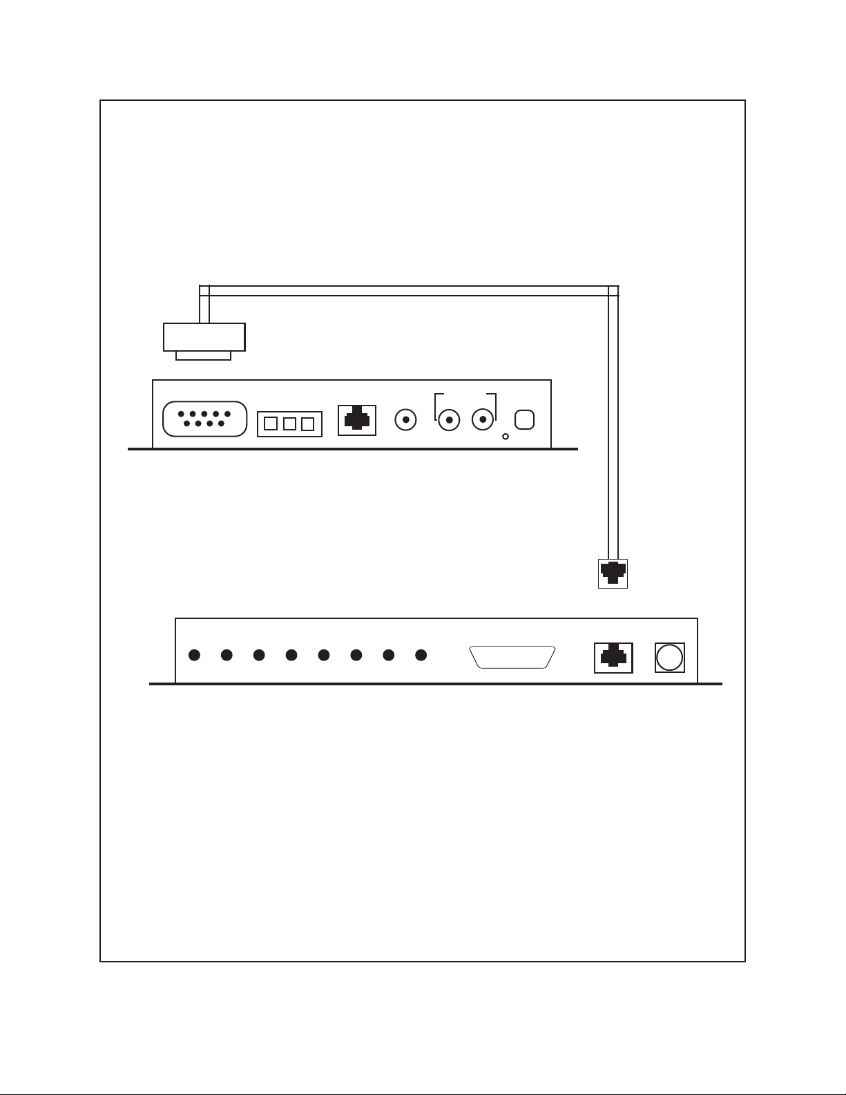
1. Connect the 9-pin interface cable (supplied with the
ICI3008/ICI3016 switcher) into the port labeled “RS
232” of the ICI3000P (refer to Fig.1).
2. Connect the modular phone plug of the interface
cable into the port labeled “DATA IN” on the
ICI3008/ICI3016 switcher (refer to Fig.1).
3. Connect the video inputs from your cameras to the
BNC’s labeled “VIDEO INPUTS” on the ICI3000P.
4. Connect a coaxial cable between the port labeled
“VIDEO OUT” of the ICI3008/ICI3016 and the port
labeled “VIDEO IN 1” of the ICI3000P.
5. If multiple ICI3008/ICI3016 switchers are being
cascaded (i.e., linked to create a larger switcher), connect a coaxial cable from the last video input of the
first Inter-Check® switcher to the port labeled
“VIDEO OUT” of the second Inter-Check® switcher.
Remove the cover of the second Inter-Check
switcher and set the 8-position dip switch to 0001
0000. Remove the cover of the first Inter-Check
switcher and set the 8-position dip switch to 0000
1000 (refer to Fig.2).
6. Connect the desired alarm outputs to any peripheral
equipment requiring a normally open contact using
the alarm interface connector supplied. Pin one corresponds to camera one; pin two with camera two;
etc. The separate wire from the Inter-Check® switcher
is ground. See Section 6.0 for alarm pin-out configuration information.
7. Power up the Inter-Check® units using the transformers supplied with each unit.
8. To verify communication between the Inter-Check
switcher and the ICI3000P, press [F9]. Press [F9]
again. Next, select camera one by entering a [1] one
followed by the [ENTER] key. The first red light
labeled [1] on the first switcher should be on. Repeat this step for each camera input on each switcher.
If an 8- or 16-position switcher has a second switcher
cascaded from it, selecting camera 8 or 16 respectively will cause the first light of the second switcher
to be activated.
NOTE: For a complete explanation of programming features, refer to the programming
section of the operation manual supplied with
the ICI3000P.
4.1 REGISTER/CAMERA/ALARM
DWELL ASSIGNMENTS
To enter the programming mode, press [ENTER]. The
following menu will be displayed:
SELECT MENU
—————————————————————
1. Register # 1 or 2
2. Operator # 1 or 2
3. Exceptions on/off
4. Camera Select
5. Screen print on/off
6. Auto camera search on/off
7. Reverse video on/off
®
8. System Program
9. Exceptions Program
®
0. Syssave/sysread/hot key list
Press [8] (SYSTEM PROGRAM) and the following
menu will be displayed:
SYSTEM MENU
—————————————————————
1. # Chars./line
2. # Lines for small scrn 1 or 2
3. Small scrn position 1 or 2
4. Large scrn position 1 or 2
5. Alarm dwell time
6. Channel parms
7. Printer parms
8. Set clock
®
9. Ext. cam. select
0. Shadow list
Press [0] (SHADOW LIST) and the following prompt
will be displayed:
Shadow List
REG CAM DWL
1.
ESC to exit or CR to edit!
2 Pelco Manual C1007M-B (2/96)
Page 3
RS-232 Alarm Data in
2 C 1
Video
Out
Video In Power
2 1
In
1 2 3 4 5 6 7 8
Alarm Out Data In Power
Figure 1. Data Cable Connection Between ICI3000P and ICI3008
Pelco Manual C1007M-B (2/96) 3
Page 4

Following is an explanation of the prompts:
REG: This is the electronic cash register (ECR)
number. If using an ICI3000P, an ECR’s number is
determined by the address assigned to it on the
ICI1000PIM installed at the register.
CAM: This is the camera number you wish to assign
to an ECR. The camera number is determined by its
video input on the ICI3008/ICI3016 switcher. When
cascading 8- or 16-position Inter-Check® switchers,
camera 8 or 16 will be the first video input of the
second switcher (refer to Fig.1). Each camera input
has a corresponding alarm output assigned to it on
the ICI3008/ICI3016 switchers. These alarm outputs
may be used in conjunction with the video inputs to
trigger peripheral devices. They may also be used
without video inputs to trigger pan/tilt presets on
PELCO matrix switchers.
DWL: The Dwell determines how long a selected
camera will remain on the monitor (in seconds) before switching to the next video camera. Entering
zero [0] for this value will cause the switcher to bypass the camera.
4.2 EDITING AN EXISTING
REGISTER LIST
To edit a camera list, press [ENTER].
Press [ESC] until the desired line is displayed. Enter the
appropriate data as described above.
Press [ESCAPE] until you reach the next line you wish
to edit or the end of the list.
Press [ENTER] to return to the SYSTEM MENU.
The Inter-Check® unit will display the previously programmed values when you re-edit the Shadow List. For
instance, if you wanted to change the dwell time of a
camera from 15 seconds to 10 seconds the following information would be displayed:
REG CAM DWL
8615 10
NOTE: Previously programmed values will
be deleted when you exit the shadow list.
1. To edit this menu, press ENTER or press ESC to
return to the SYSTEM MENU.
2. Enter the register number you wish to select then
press ENTER.
3. Enter the camera number (or alarm output) you would
like assigned to this register followed by ENTER.
4. Select the dwell time for this camera in seconds or
zero [0] to bypass then press ENTER.
5. Repeat these steps until all selected registers have a
camera number and dwell time assigned to them.
This list will hold 32 thirty-two line items.
5.0 OPERATION
5.1 CAMERA SEQUENCING
While in the monitoring mode, the Inter-Check® switcher
will sequence through the camera presets according to
the programmed dwell time assigned to each camera. To
stop camera sequencing, simply press the [S] button on
your keyboard. To resume switching, press the [S] key
again.
5.2 MANUAL REGISTER MONITORING
While in the monitoring mode, press [F1].
To display the transaction data on the LEFT side of the
monitor, press [1] one.
To display the transaction data on the RIGHT side of the
monitor, press [2] two.
Enter the register number to be monitored; then press
[ENTER].
4 Pelco Manual C1007M-B (2/96)
Page 5

6.0 ALARM OUTPUTS
Both the ICI3008 and ICI3016 “shadow switchers” provide alarm outputs for alarming other peripheral equipment. The ICI3008 provides eight (8) alarm outputs and
the ICI3016 provides sixteen (16) alarm outputs.
A particular alarm output is enabled according to the
camera selected.
6.0 ALARM PIN-OUT CONFIGURATION
For example; when camera 4 is selected, alarm output
4 will be enabled. The output for both switchers is normally open.
The following diagrams list the pin assignments for both
switchers. Use this information in wiring external,
alarmable equipment.
25-PIN CONNECTOR FOR ICI3016
13
1
25
14
Pin # Alarm Output
1 Alarm Output 1
2 Alarm Output 2
3 Alarm Output 3
4 Alarm Output 4
5 Alarm Output 5
6 Alarm Output 6
7 Alarm Output 7
8 Alarm Output 8
9 Alarm Output 9
10 Alarm Output 10
11 Alarm Output 11
12 Alarm Output 12
13 Alarm Output 13
14 Alarm Output 14
15 Alarm Output 15
16 Alarm Output 16
17-25 Common Ground
9-PIN CONNECTOR FOR ICI3008
5 4 3 2 1
9 8 7 6
Pin # Alarm Output
1 Alarm Output 5
2 Alarm Output 7
3 Alarm Output 6
4 Alarm Output 8
5 Alarm Output 1
6 Alarm Output 3
7 Alarm Output 2
8 Alarm Output 4
9 Common Ground
Pelco Manual C1007M-B (2/96) 5
Page 6

12
34 5678
1 2 3 4 5 6 7 8
OPE N
OPEN
DI P S WI TCH DESCRI PT I ON--
Swi t c h # Funct i on
1
2
3
4
5
6
7
8
B ank addr ess
Bank Address
B ank addr ess
Bank Address
B ank addr ess
Bank Address
B ank addr ess
Bank Address
Loop Select
l oop
baud r at e
NC
NC
sel ect
Baud Rate Select
NC
NC
sel ect
Co v e r mu s t b eremoved t o acc ess t his DIP Swi t c h
*
TO MONI
NOTE: Cover must be removed to access this dip switch.
CAMERAS 16- 31
CAMERAS 1 - 1 5
TOR ORVCR
Loop =
A ddr es s = 0001
VI DEO I NPUT S
Loop = 1
A ddr ess =
VI DEO I NPUT S
0
0000
Shadow switchers are available in either 8 or 16 positions.
12345678910111216 1 5 14 13VI D EO OUT
12345678910111216 1 5 14 13VI D EO OUT
Figure 2. Cascading the ICI30008 or ICI3016
6 Pelco Manual C1007M-B (2/96)
Page 7

Notes:
Pelco Manual C1007M-B (2/96) 7
Page 8

7.0 WARRANTY AND RETURN
INFORMATION
WARRANTY
Pelco will repair or replace, without charge, any merchandise proved
defective in material or workmanship for a period of one year after the date
of shipment.
Exceptions to this warranty are as noted below:
• Five years on FT/FR8000 Series fiber optic products.
• Three years on Genex
keyboard).
• Three years on Camclosure
CC3701H-2, CC3701H-2X, CC3751H-2, CC3651H-2X, MC3651H-2,
and MC3651H-2X camera models, which have a five-year warranty.
• Two years on standard motorized or fixed focal length lenses.
• Two years on Legacy
DF5/DF8 Series fixed dome products.
• Two years on Spectra
ing when used in continuous motion applications.
• Two years on Esprit
wiper blades).
• Eighteen months on DX Series digital video recorders, NVR300
Series network video recorders, and Endura
network-based video products.
• One year (except video heads) on video cassette recorders (VCRs).
Video heads will be covered for a period of six months.
• Six months on all pan and tilts, scanners or preset lenses used in
continuous motion applications (that is, preset scan, tour and auto scan
modes).
Pelco will warrant all replacement parts and repairs for 90 days from the
date of Pelco shipment. All goods requiring warranty repair shall be sent
freight prepaid to Pelco, Clovis, California. Repairs made necessary by
reason of misuse, alteration, normal wear, or accident are not covered
under this warranty.
Pelco assumes no risk and shall be subject to no liability for damages or
loss resulting from the specific use or application made of the Products.
Pelco’s liability for any claim, whether based on breach of contract,
negligence, infringement of any rights of any party or product liability,
relating to the Products shall not exceed the price paid by the Dealer to
Pelco for such Products. In no event will Pelco be liable for any special,
incidental or consequential damages (including loss of use, loss of profit
and claims of third parties) however caused, whether by the negligence
of Pelco or otherwise.
The above warranty provides the Dealer with specific legal rights. The
Dealer may also have additional rights, which are subject to variation from
state to state.
If a warranty repair is required, the Dealer must contact Pelco at (800) 2899100 or (559) 292-1981 to obtain a Repair Authorization number (RA),
and provide the following information:
1. Model and serial number
2. Date of shipment, P.O. number, Sales Order number, or Pelco invoice
number
3. Details of the defect or problem
If there is a dispute regarding the warranty of a product which does not fall
under the warranty conditions stated above, please include a written
explanation with the product when returned.
Method of return shipment shall be the same or equal to the method by
which the item was received by Pelco.
®
Series products (multiplexers, server, and
®
and fixed camera models, except the
®
, CM6700/CM6800/CM9700 Series matrix, and
®
, Esprit®, ExSite™, and PS20 scanners, includ-
®
and WW5700 Series window wiper (excluding
™
Series distributed
RETURNS
In order to expedite parts returned to the factory for repair or credit, please
call the factory at (800) 289-9100 or (559) 292-1981 to obtain an
authorization number (CA number if returned for credit, and RA number
if returned for repair).
All merchandise returned for credit may be subject to a 20% restocking
and refurbishing charge.
Goods returned for repair or credit should be clearly identified with the
assigned CA or RA number and freight should be prepaid. Ship to the
appropriate address below.
If you are located within the continental U.S., Alaska, Hawaii or Puerto
Rico, send goods to:
If you are located outside the continental U.S., Alaska, Hawaii or Puerto
Rico and are instructed to return goods to the USA, you may do one of the
following:
If the goods are to be sent by a COURIER SERVICE, send the goods to:
If the goods are to be sent by a FREIGHT FORWARDER, send the goods
to:
Service Department
Pelco
3500 Pelco Way
Clovis, CA 93612-5699
Pelco
3500 Pelco Way
Clovis, CA 93612-5699 USA
Pelco c/o Expeditors
473 Eccles Avenue
South San Francisco, CA 94080 USA
Phone: 650-737-1700
Fax: 650-737-0933
®
PELCO
3500 Pelco Way
Clovis, CA 93612-5699 USA
(559) 292-1981 • (800) 289-9100
FAX (800) 289-9150 or (559) 292-3827
International customers call 1-559-292-1981
or FAX 1-559-348-1120
Pelco, the Pelco logo, Camclosure, Esprit,
Genex, Legacy, and Spectra are registered
trademarks of Pelco.
Endura and ExSite are trademarks of Pelco.
© Copyright 1996, Pelco. All rights reserved.
(Product specifications subject to change
without notice.)
C1007M-B
8 Pelco Manual C1007M-B (2/96)
 Loading...