

Page 1

®
Inter-Check ICI1000S Series
Cash Register Interface System
®
™
Installation/Operation Manual
C1000M-B (1/96)
PELCO • 3500 Pelco Way, Clovis, CA 93612-5699 • USA • (800) 289-9100 or (1-559) 292-1981
FAX (800) 289-9150 or (1-559) 292-3827
Page 2

TABLE OF CONTENTS
Section Page
1.0 WARNINGS........................................................................................................................................1
2.0 SCOPE...............................................................................................................................................2
2.1 DESCRIPTION .........................................................................................................................2
3.0 INSTALLATION...................................................................................................................................3
3.1 INST ALLING INTERF ACE CABLE ...........................................................................................3
3.2 BASIC INST ALLA TIONS...........................................................................................................3
3.3 VIDEO ADJUSTMENTS ...........................................................................................................6
4.0 INTER-CHECK ON-BOARD KEYP AD OPERATION..........................................................................7
4.1 PROGRAMMING THE ICI1000SI .............................................................................................7
4.2 THE NV MEMORY WRITE PROTECT SWITCH......................................................................7
4.3 CHANNEL SETUP....................................................................................................................9
4.3.1 Communication Setup .................................................................................................9
4.3.2 Communication Parameters ........................................................................................9
4.3.3 Device Addresses ......................................................................................................10
4.4 DA T A FORMAT/COMMUNICATION PROTOCOL...................................................................10
4.5 VIDEO PARAMETERS ...........................................................................................................11
4.6 SYSTEM PARAMETERS........................................................................................................11
4.6.1 Alarm Output .............................................................................................................11
4.6.2 Carriage Return Control ............................................................................................12
4.6.3 Camera Screen Data Position ...................................................................................12
4.6.4 Printer Settings ..........................................................................................................12
4.6.5 Exception Alarm Settings ..........................................................................................13
4.6.6 Exception Alarm Text Edit ..........................................................................................14
4.6.6.1 Keypad Definitions......................................................................................14
4.6.7 Programming Stratagies ............................................................................................15
4.6.8 Exception Column Line ..............................................................................................17
4.7 CLOCK SETUP ......................................................................................................................17
4.7.1 Set Clock ...................................................................................................................17
4.7.2 Clock ID On and Screen Position Set ........................................................................18
4.7.3 Clock ID Off ...............................................................................................................18
4.7.4 USA Standard Date ...................................................................................................18
4.7.5 European Date...........................................................................................................18
4.7.6 Auto Clock Set ...........................................................................................................18
Inter-Check® is a registered trademark of Pelco.
®Pelco and the Pelco logo are registered trademarks of Pelco.
©Copyright 1996, Pelco. All rights reserved.
ii Pelco Manual C1000M-B (1/96)
Page 3

TABLE OF CONTENTS (Continued)
Section Page
4.8 LOCA TION ID SETUP ............................................................................................................18
4.8.1 Location ID Program ..................................................................................................18
4.8.2 Location ID On and Screen Position Set ...................................................................19
4.8.3 Location ID Off ...........................................................................................................19
4.9 CUSTOMER HEADER ...........................................................................................................19
4.10 DIAGNOSTICS .......................................................................................................................19
4.10.1 Program Transfer .......................................................................................................20
4.10.2 (DL) Burn-In Test .......................................................................................................20
4.10.3 (DL) Input Channel Port T est .....................................................................................20
4.10.4 Memory Tests ............................................................................................................21
4.10.5 System Signals T est...................................................................................................21
4.10.6 Video Screen Test......................................................................................................21
4.10.7 Graphics Screen T est.................................................................................................21
4.10.8 (DL) Pelco PIM Default Load .....................................................................................22
4.11 ALARM INPUT........................................................................................................................23
4.11.1 Alarm Input On/Off.....................................................................................................23
4.11.2 Alarm Trigger Dwell....................................................................................................24
4.11.3 Screen Link ................................................................................................................24
4.11.4 Auxiliary Print Link .....................................................................................................24
4.11.5 Alarm Text ..................................................................................................................24
4.12 ALARM PROGRAMMING ......................................................................................................24
4.13 THE NV MEMORY WRITE PROTECT SWITCH.................................................................... 25
5.0 TROUBLESHOOTING .....................................................................................................................26
5.1 TROUBLESHOOTING FLOW CHART ...................................................................................27
6.0 SPECIFICA TIONS............................................................................................................................29
7.0 WARRANTY AND REPAIR INFORMATION.....................................................................................29
APPENDIX A. HEXADECIMAL, DECIMAL AND BINARY CONVERSION TABLES ................................. 30
APPENDIX B. ICI1000PIM SWITCH SETTINGS.......................................................................................33
Pelco Manual C1000M-B (1/96) iii
Page 4

LIST OF ILLUSTRATIONS
Figure Page
1 Basic ICI1000S Configuration Wiring Diagram ............................................................................3
2 ICI1000PIM Wiring Configuration ................................................................................................4
3 Standard RS-232 Style Wiring Configuration...............................................................................4
4 Printer Output and Alarm Input Wiring.........................................................................................5
5 Video Adjustment Locations ........................................................................................................6
6 Keypad Layout ................................................................................................................. ............7
7 Program Transfer Wiring Diagram..............................................................................................20
8 Printer Output and Alarm Input Wiring.......................................................................................23
9 ICI1000PIM Switch Settings ......................................................................................................36
LIST OF TABLES
Table Page
1 Data Screen ID ..........................................................................................................................11
2 Label Descriptors.......................................................................................................................25
3 ICI1000S Series Pinouts............................................................................................................25
REVISION HISTORY
Manual # Date Comments
C1000M — Original version.
C1000M-A 11/95 Revised to incorporate Programming Menu Map, Section 4.0,
and Troubleshooting Flow Chart, Section 5.1.
C1000M-B 1/96 Revised to include Appendix B, ICI1000PIM Switch Settings.
iv Pelco Manual C1000M-B (1/96)
Page 5
INSTALLATION/OPERATION MANUAL
ICI1000S SERIES INTER-CHECK
®
CASH REGISTER INTERFACE SYSTEM
1.0 WARNINGS
Prior to installation and use of this product, the following
WARNINGS should be observed.
1. Installation and servicing should only be done by
qualified service personnel and conform to all local
codes.
2. Unless the unit is specifically marked as a NEMA
Type 3, 3R, 3S, 4, 4X, 6 or 6P enclosure, it is
designed for indoor use only and it must not be
installed where exposed to rain and moisture.
3. The product and/or manual may bear the following
marks:
This symbol indicates that dangerous voltage
constituting a risk of electric shock is present
within this unit.
CAUTION:
TO REDUCE THE RISK OF ELECTRICAL
SHOCK, DO NOT REMOVE COVER. NO
USER-SERVICEABLE PARTS INSIDE.
REFER SERVICING TO QUALIFIED
SERVICE PERSONNEL.
4. Only use replacement parts recommended by Pelco.
5. After replacement/repair of this unit’s electrical
components, conduct a resistance measurement
between line and exposed parts to verify the exposed
parts have not been connected to line circuitry.
This symbol indicates that there are important
operating and maintenance instructions in the
literature accompanying this unit.
CAUTION:
RISK OF ELECTRIC SHOCK.
DO NOT OPEN.
Please thoroughly familiarize yourself with the information in this manual
prior to installation and operation.
Pelco Manual C1000M-B (1/96) 1
Page 6

2.0 SCOPE
The information contained within this manual covers
the installation and operation of the Inter-Check
ICI1000S Series cash register interface system.
Installation should be in accordance with all applicable
local and national electric codes, utilizing approved materials only.
Please familiarize yourself with the information in this
manual prior to installation and operation.
2.1 DESCRIPTION
The Inter-Check terminal monitor, or P.O.S., interfaces
with most ATM machines and popular cash registers. It
is compatible with most standard CCTV cameras, video
tape recorders and monitors. The Inter-Check is the heart
of a large family of Pelco products which are designed
to reduce losses in any financial institution.
In addition to the high performance and reliability
you’ve come to expect from Pelco products, the InterCheck ICI1000S Series offers the following MAIN
®
FEATURES:
• Monitors one device, cash register or ATM machine.
• Exception flagging for special alarm flags such as
VOID or REFUND.
• Exception flagging on numerical values such as
price and the manipulation of these values.
• 30 separate exceptions can be programmed.
• One programmable alarm output for VCR control.
• One programmable alarm input for sensing of any
closure.
• Completely programmable data channel.
• Self-diagnostics to check for proper operation.
• Easy on-screen, menu-driven programming.
• Non-volatile memory for program storage (no battery needed).
• Horizontal and vertical fine tune controls.
• Character size, intensity and video gain controls.
• Program transfer function between another InterCheck ICI1000S Series unit or Personal Computer
(PC).
• Program transfer between an Inter-Check ICI1000S
Series and a PC requires special software designed
by Pelco Systems. If interested in this option, contact a Pelco representative.
• Compact 64 function keypad used to program the
Inter-Check ICI1000S Series.
• The Inter-Check ICI1000S Series keypad can be
ordered for either external operation or hidden internal operation. Your choice must be specified
upon the initial order.
2 Pelco Manual C1000M-B (1/96)
Page 7
3.0 INSTALLATION
To begin installation, refer to the following instructions
and Figures 1 and 2.
3.1 INSTALLING INTERFACE CABLE
1. Install interface cable and PIM (if applicable) into
the cash register according to the instructions supplied with your interface cable. Do not power up
PIM .
NOTE: Do not mount the Inter-Check
ICI1000S Series unit until all connections are
made and programming is complete. V ideo adjustments on the bottom of the Inter-Check
ICI1000S Series may need to be accessible
during the initial set-up.
3.2 BASIC INSTALLATIONS
For basic installations, perform the following steps:
2 Install an 18 gauge, two-conductor shielded cable
between the interface cable/PIM and the ICI1000S
unit using the ICI1000WK (wiring kit) supplied
with your ICI1000S (refer to Figures 2 and 3). This
kit contains two RJ14 phone jacks and one straightthrough six conductor cable.
WARNINGS: Do not power up the InterCheck ICI1000S Series unit until all other connections have been made.
Only use the power supply supplied with the Inter-Check
ICI1000S Series unit. Other power supplies may damage
the unit.
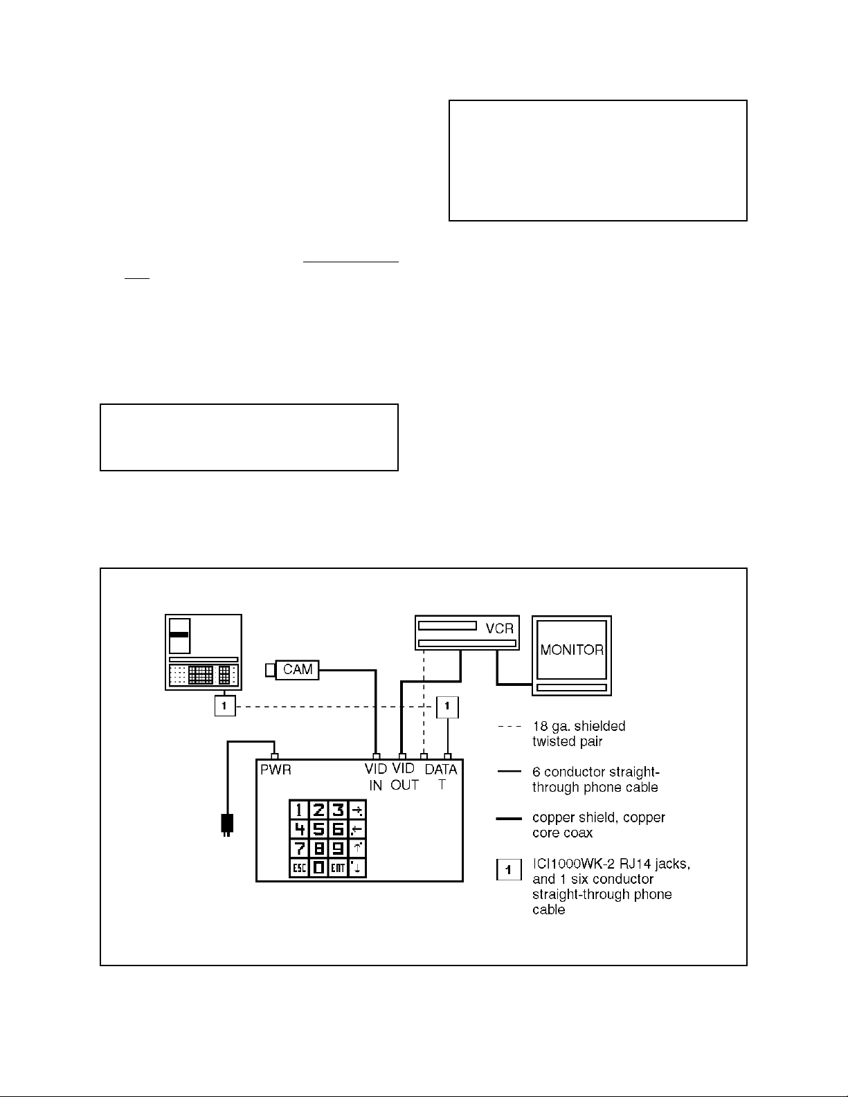
1. Connect the cable from your video camera to the
BNC labeled “VIDEO IN” on the Inter-Check
ICI1000S (refer to Figure 1). This normally comes
from your camera, splitter, switcher or quad. For
Coaxitron matrix installations, connect the cable
from the desired MONITOR OUTPUT to the BNC
labeled “VIDEO IN” on the Inter-Check unit.
2. Connect a cable from the BNC labeled “VIDEO
OUT” on the Inter-Check ICI1000S Series to the
video input of your video cassette recorder or
monitor.
Figure 1. Basic ICI1000S Configuration Wiring Diagram
Pelco Manual C1000M-B (1/96) 3
Page 8
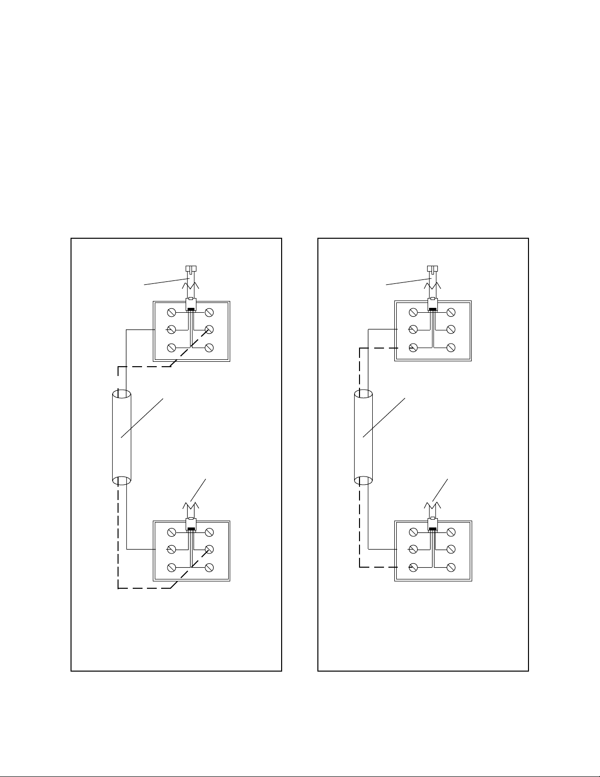
To Inter-Check Unit
To Inter-Check Unit
Straight through
phone cable
WH
BK
RD
BL
YL
GR
User-supplied cable.
18 AWG shielded wire is
suggested
From ICI1000PIM
WH
BK
BL
YL
Straight through
phone cable
WH
BK
RD
BL
YL
GR
User-supplied cable.
18 AWG shielded wire is
suggested
From RS-232 style input
WH
BK
BL
YL
RD
GR
RD
GR
NOTE: For RS-232 style applications only.
Figure 2. ICI1000PIM Wiring Configuration
Figure 3. Standard RS-232 Style
Wiring Configuration
4 Pelco Manual C1000M-B (1/96)
Page 9
3. Connect the data cable from the register interface
cable (or PIM) to “DATA IN” on the Inter-Check
ICI1000S, using the ICI1000WK and 18 gauge, 2conductor shielded cable (see Figure 1).
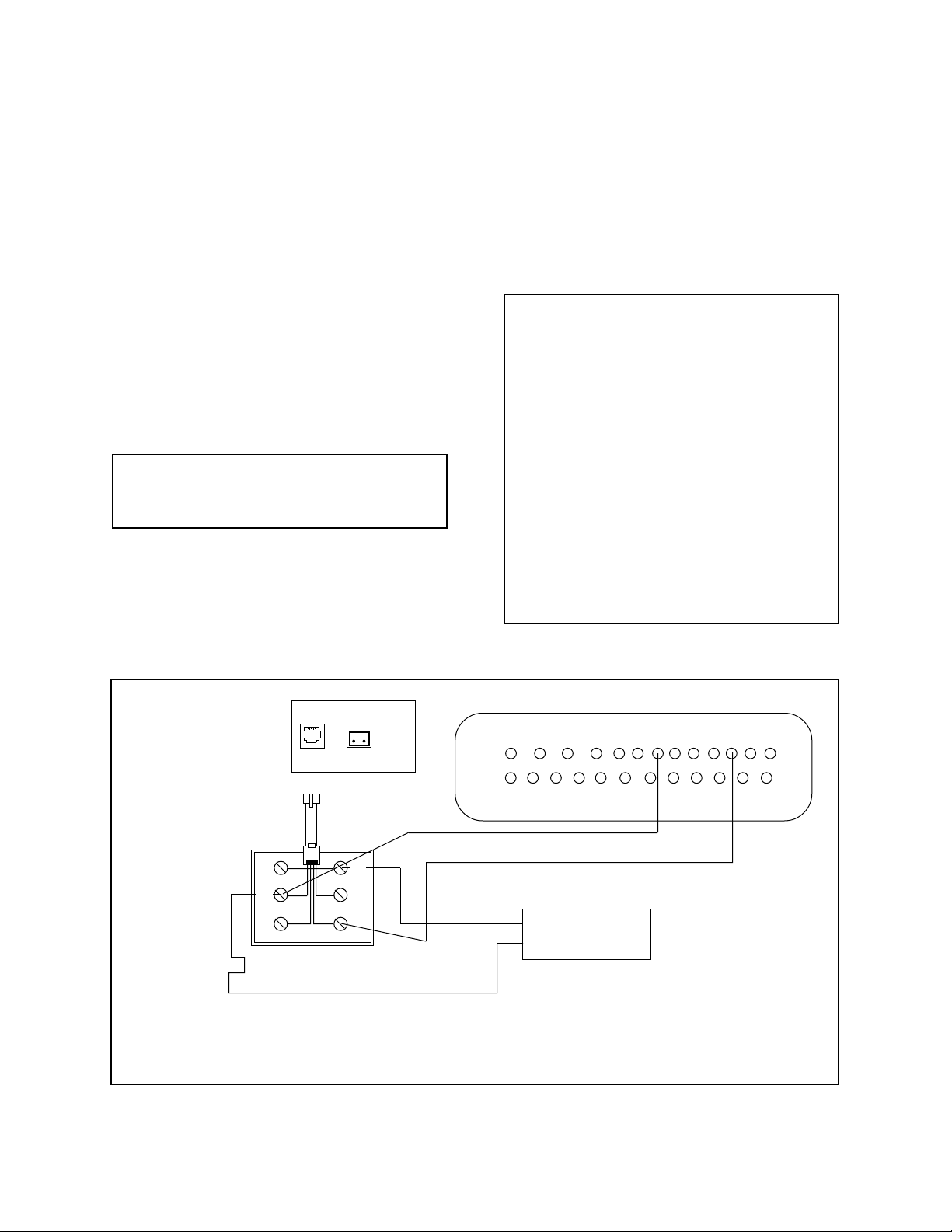
4. If using alarms, attach a 22-gauge, 2-conductor
shielded cable from the “ALARM OUT” of the
Inter-Check ICI1000S Series unit to your VCR,
switcher, or other alarmable device.
8. Plug the power supply for the ICI1000PIM into a
120 VAC outlet. The monitor should now display
the register model number.
9. If using the auxiliary print feature, and/or alarm
inputs, follow the wiring diagram in Figure 4 for
proper installation.
5. Plug the power supply for the Inter-Check
ICI1000S Series unit into a 120 VAC outlet.
6. Use the keypad on top of, or inside, the ICI1000S
chasis to set the standard PIM defaults. Press ENT ,
6, 8 and then ESC to return to monitoring mode.
This step is required for all ICI1000S systems (refer to Figure 4).
NOTE: ICI1000SI models have an internal
keypad; ICI1000SE models have an external
keypad.
7. Set the dip switches on the front of the ICI1000PIM
to match the setting for your register model number. Use the ICI1000PIM switch settings located
in the ICI1000PIM manual or Appendix B of this
manual. If your register does not require an
ICI1000PIM, disregard this step.
Alarm
Data
Out
In
NOTE: The monitor should now show the initialization message shown below .
Pelco
INTER-CHECK/S VER X.X
ROM CHECK = YYYY
CALC. ROM CHECK = YYYY
SYSTEM BEING INITIALIZED!
MM VER. Z.Z
(register model # displayed here)
NOTE: If you do not receive this message,
refer to the troubleshooting guide in Section 5.0.
If your installation does not require the use of
an ICI1000PIM, the register model number will
not appear.
13 12 11 10 9 8 7 6 5 4 3 2 1
25 24 23 22 21 20 19 18 17 16 15 14
WH
BK
RD
BL
YL
GR
Alarm
Contact
NOTE: A serial printer used with the Inter-Check ICI1000S
Series must be set at 1200 baud, 8 bits, no parity.
Figure 4. Printer Output and Alarm Input Wiring
Pelco Manual C1000M-B (1/96) 5
Page 10
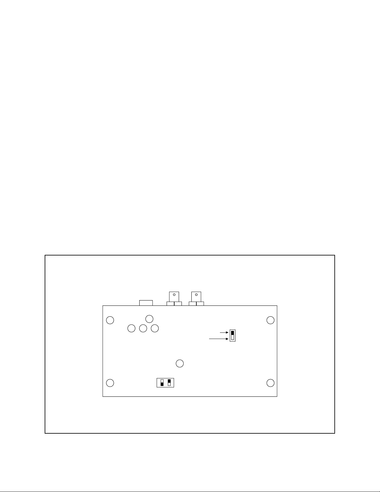
3.3 VIDEO ADJUSTMENTS
All video adjustments are located on the bottom of
the Inter-Check unit (refer to Figure 5). Using a nonmetallic screwdriver, make any necessary adjustments
as follows:
• Horizontal Positioning adjusts the height of the
displayed text. To raise the text position, turn the
potentiometer labeled “H” slightly clockwise. This
adjustment will also correct double-sized characters appearing on the screen.
• V ertical Positioning adjusts the lateral position of
the displayed text. T o move the text to the left, turn
the potentiometer labeled “V” slightly clockwise.
This adjustment will also correct “jittering” text.
• Intensity adjusts the brightness of the text. To increase the intensity of the text, turn the potentiometer labeled “I” slightly clockwise.
• Gain adjusts the entire video screen. T oo much gain
will distort the video picture. T o reduce video gain,
turn the potentiometer labeled “G” slightly counterclockwise.
• Horizontal Size adjusts the width of the text. To
increase the text width, turn the potentiometer labeled “S” slightly clockwise.
• Character Size adjusts the size of the characters.
There are four selections. Set the switches marked
“C” in one of the following choices: both up, both
down, first switch up and second one down, or first
switch down and second one up.
G
VHI
UNLOCKED
LOCKED
NV MEMORY
SWITCH
S
C
Figure 5. Video Adjustment Locations
6 Pelco Manual C1000M-B (1/96)
Page 11
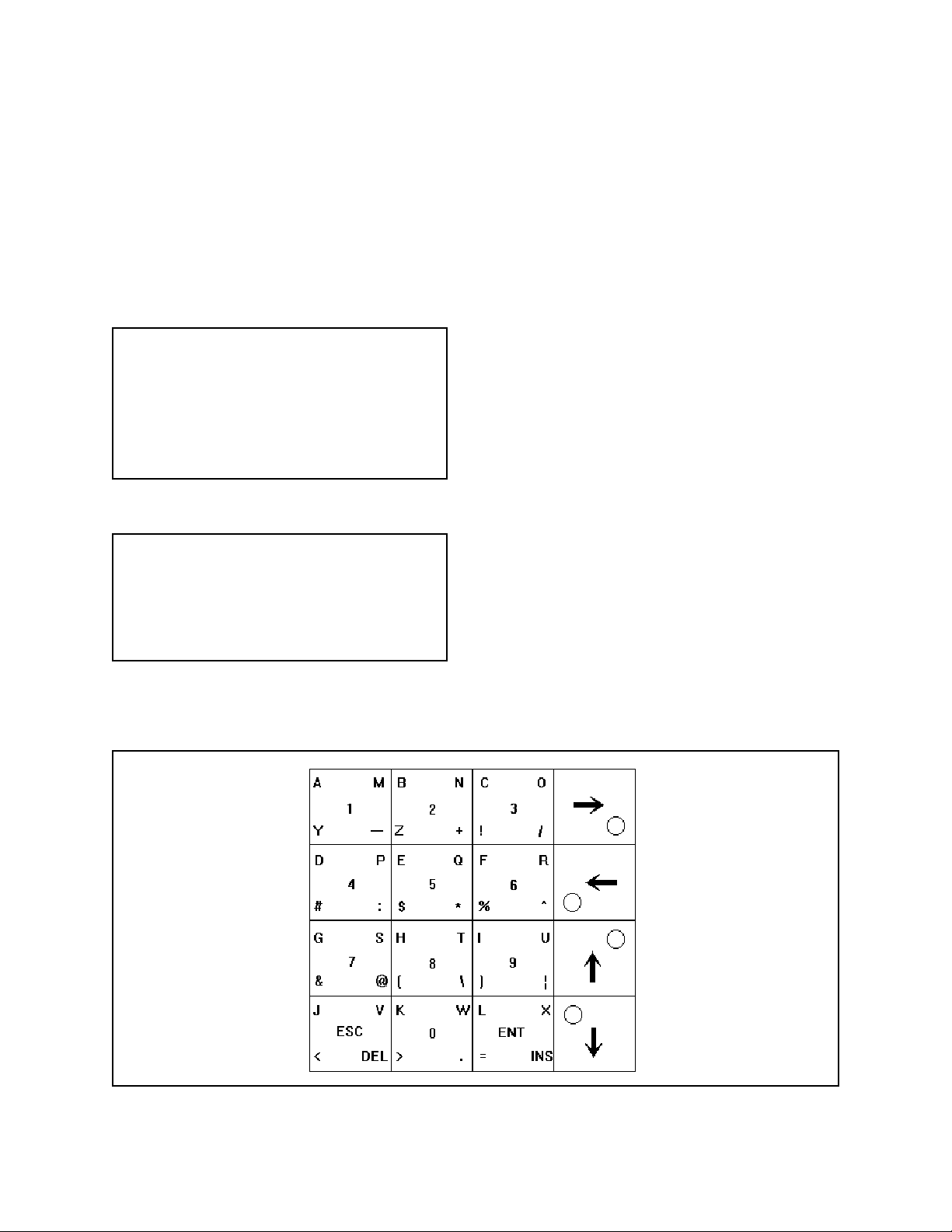
4.0 INTER-CHECK ON-BOARD
KEYPAD OPERATION
The Inter-Check ICI1000S Series features a compact,
64 function keypad used for all programming functions.
Refer to Figure 6. The keypad contains 16 keys. The
four keys on the right side of the keypad are used for
both cursor movement and “shift operations”. The remaining keys contain alpha, numeric, and other characters for editing your program. These keys each contain five functions when used with the shift keys.
To select: Press:
White Character Desired Key
Color Character Cursor key of matching color
and then desired key.
Cursor Movement Desired arrow key twice.
Main Menu Enter (ENT)
Exit Main Menu Escape (ESC)
4.1 PROGRAMMING THE ICI1000SI
NOTE: Please familiarize yourself with the
information in this manual prior to installation
and operation. Contact the customer's register
dealer/installer prior to installation and operation. Some warranties and/or service agreements may be affected.
If your Inter-Check unit is an ICI1000SI, it utilizes an
internal keypad for programming all parameters. Follow the steps below prior to programming.
1. Power down the Inter-Check ICI1000SI unit.
2. Remove the four cover screws with a Phillips
screwdriver and set the cover aside.
3. Power up the ICI1000SI unit.
4. Program the Inter-Check unit for your particular
application.
5. When finished programming, replace the cover and
screw down firmly.
4.2 THE NV MEMORY WRITE PROTECT
SWITCH
Your new Inter-Check ICI1000S Series incorporates a
Non-Volatile (NV) type memory. This type of memory
does not require a battery to operate. Refer to Figure 5
for the location of this switch and note the locked and
unlocked positions. This switch must be positioned in
the UNLOCKED position if you intend on programming the Inter-Check ICI1000S Series unit. If the switch
is in the LOCKED position and you try to enter programming data, an “ERROR IN WRITING NV
MEMORY !!!” warning will be displayed on the monitor screen. T o allow programming, simply position the
write protect switch to the UNLOCKED position. When
programming is complete, position the switch to the
LOCKED position. This will protect your programming
from possible errors that may occur during AC power
fluctuations or complete Inter-Check ICI1000S Series
power loss.
Figure 6. Keypad Layout
Pelco Manual C1000M-B (1/96) 7
Page 12
ICI1000S PROGRAMMING MENU TREE
Monitoring
Mode
↵ ENT
Main Program Menu
1. Channel 1 Setup
2. System Parameters
3. Clock Setup
4. Location ID Setup
5. Customer Header
6. Diagnostics
7. Alarm Inputs
Channel Program Menu
1. Communication Setup
2. Data Format/Communication Protocol
3. Video Parameters
4. A TM Line Select
System Program Menu
1. Alarm Outputs
2. Carriage Return Control
3. Channel Screen Data
Position
4. Printer Settings
5. Exception Alarm Settings
6. Exception Alarm Text Edit
7. Exception Column Line
Clock Program Menu
1. Set Clock
2. Clock ID On and Screen
Position Set
1
2
3
4
6
7
3. Clock ID Off
4. USA Standard Date
5. European Date
6. Auto Clock Set
Location ID Setup Menu
1. Location ID Program
2. Location ID on and
Screen Position Set
3. Location ID Off
Communication Setup Menu
1
1. Communication Parameters
2. Device Addresses
Carriage Return Menu
2
1. Exception Auto CR
2. End Of Line Stop
Diagnostics Selection Menu
1. Programm Transfer
2. (DL) Burn In Test
3. (DL) Input Channel Port
Test
4. Memory T ests
5. Signals T est
6. Screen T est
7. Graphics T est
8. (DL) PIM Default Load
Alarm Input Menu
1. Alarm Input On/Off
2. Alarm Trigger Dwell
3. Screen Link
4. Auxiliary Print Link
5. Alarm T ext
↵ ENT Key moves Inter-Check
into the programming
mode from the monitoring
mode
ESC Key returns to the
previous menu
Select catagories by
number
8 Pelco Manual C1000M-B (1/96)
Page 13

4.3 CHANNEL SETUP
There are two ways you can view your current channel
parameters:
1. Press the “1” key on your keypad while in the
monitoring mode.
NOTE: If the current settings are acceptable, press the ESC key which returns to the
CHANNEL PROGRAM SELECTION
MENU. If you wish to change the communication parameters, press “1”. To change the
device addresses press “2”.
2. Select CHANNEL SETUP (#1) in the MAIN PROGRAM MENU.
After executing one of these steps, an example of what
you might see is shown below:
SELECTED: CHANNEL
Pelco PIM STANDARD
9600 BAUD,8 BITS,OFF PARITY
NRZ,ASCII,DATA INVERT
DEVICE ADDRESS 1 = 00H 0
DEVICE ADDRESS 2 = 00H 0
NOR. VID,OFF ID.,30 CHARACTERS
18 LINES,DATA DWELL=0
ALARM DWELL : 6/D1
EALRM = ON/VP PNTR = OFF
CHANNEL PROGRAM SELECTION MENU
1. COMMUNICATION SETUP
2. DA T A FORMA T/COMMUNICATION PROTOCOL
3. VIDEO PARAMETERS
4.3.1 Communication Setup
This selection allows you to set COMMUNICATION
P ARAMETERS and DEVICE ADDRESSES. The communication parameters must be programmed correctly
in order for the Inter-Check ICI1000S Series to accept
data from your interface. Device addresses are used predominantly in ATM programming. Upon entering this
menu, you will notice that the channel’s current COMMUNICATION SETUP parameters are displayed as
shown below.
COMMUNICATION SETUP MENU
4.3.2 Communication Parameters
This menu enables you to program the data string format, baud rate, and character set into the Inter-Check
ICI1000S series.
NOTE: If you do not want to change items
within this menu, simply press ESC. The ESC
key will save the contents on the current line
and bring you to the prompt on the next line.
BAUD RATE =?
This prompt enables you to change the baud rate. Enter
the appropriate data and press ENT to save. Use 9600
when connecting to a PIM. Setting the baud to 0 will
turn off the data channel.
BITS (7 or 8) =?
Enter the appropriate number of data bits by pressing a
7 or 8 on your keypad. Use 8 when connecting to a
PIM.
PARITY = 1. ODD, 2. OFF, 3. EVEN
Enter the correct parity configuration of your device
by selecting 1, 2 or 3. Choose #2 for a PIM.
1=NRZ OR 2=NRZI
Choose the appropriate code transmission format by
selecting 1 or 2. NRZ is the most common format. An
exception to this is the SNA/SDLC type of communications. Select #1 for normal PIM applications.
SELECTED: 9600 BAUD,8 BITS,OFF PARITY
NRZ,ASCII,DATA INVERTED
DEVICE ADDRESS 1 = 00H 0
DEVICE ADDRESS 2 = 00H 0
1. COMMUNICATION PARAMETERS
2. DEVICE ADDRESSES
Pelco Manual C1000M-B (1/96) 9
Page 14

1=ASCII OR 2=EBCDIC
The fifth prompt sets up the character set for the InterCheck ICI1000S Series. Press a “1” to select ASCII
and “2” for EBCDIC. The ASCII character set is the
most common whereas EBCDIC is used predominantly
in IBM systems. Select ASCII when connecting to a
Pelco PIM.
1=DA TA NON INVER T OR 2=DA TA INVERT
This prompt sets up the Inter-Check ICI1000S series to
receive either inverted or non-inverted data. This selection varies from one register to the next. Choose
DATA INVERT in PIM applications.
After you have answered all of the prompts, the InterCheck ICI1000S Series will show you the changes (if
any) you have made. If the changes are correct, press
ESC. If the changes are incorrect, follow the same steps
just described. Again note that if you do not want to
edit a certain parameter you can skip and save the initial settings by pressing ESC.
4.3.3 Device Addresses
Select this menu by pressing #2 in the Communication Setup Menu. As mentioned earlier , DEVICE ADDRESSES are used in ATM installations. A device
address is the electronic address of the specific ATM
being monitored. The Inter-Check ICI1000S Series
allows you to enter two DEVICE ADDRESSES.
NOTE: Appendix A illustrates a Hexadecimal to Decimal conversion chart that you may
find helpful. Also, set the unused device address to 00H.
After pressing #2 the screen will display:
DEVICE ADDRESS -1 3 DECIMAL DIGITS (000-
255) = ?
This prompts you to enter the appropriate address up to
three digits in length. This address must also be between the specified boundaries, 000-255. If less than
three digits are used, you must press ENT to save. Pressing the ESC key will return you to the CHANNEL PROGRAM MENU.
The next prompt reads:
DEVICE ADDRESS -2 3 DECIMAL DIGITS (000-
255) = ?
Enter the appropriate address as explained above. After pressing ESC or entering an address you will be in
the CHANNEL PROGRAM MENU once again. The
current programmed addresses are displayed in both
Hexadecimal and Base 10 formats.
NOTE: If you are using SNA or SDLC formats, make both device addresses the same
value.
NOTE: Setting both addresses to 00 puts the
Inter-Check ICI1000S Series unit into diagnostics mode. In this mode the Inter-Check
ICI1000S Series unit will display all network
activity including the proper device address in
your installation.
4.4 DATA FORMAT/COMMUNICATION
PROTOCOL
Select this menu by pressing #2 in the CHANNEL
PROGRAM MENU. The menu allows you to choose
the type of device you are connecting to. After pressing
#2 the current settings will be displayed. An example
might be:
DATA PROTOCOL MENU
SELECTED: PIM STANDARD
To select the proper communication protocol for your
application, use the ENT key or the up and down cursor control keys to scroll through your options. When
you reach the device, save the selection by pressing
ESC.
Current options include:
• PIM STANDARD
• PIM GRAPHICS
• ICL PRINTER
• WAYNE-DRESSER PRINTER
• DIEBOLD 910/911 : NCR 751/279
• DIEBOLD 910/911 : TC 500/700
• DIEBOLD 910/911 : TC 500/700 SYNC
• DIEBOLD 910/911 : IBM 3275
• DIEBOLD 910/911 : IBM 2260
• DIEBOLD 910/911 : IBM 2265
• DIEBOLD 910/911 : SNA/SDLC
• IBM3624
• NCR NATIVE MODE
• IBM NATIVE MODE
• RS232 STANDARD PRINTER
10 Pelco Manual C1000M-B (1/96)
Page 15

4.5 VIDEO PARAMETERS
NUMBER OF LINES DISPLAYED (01-18)
To view the video parameters setting press #3 in the
CHANNEL PROGRAM MENU. The Inter-Check
ICI1000S Series will display the current settings. Pressing ESC will skip the current line and allow you to continue in the CHANNEL PROGRAM MENU.
VIDEO PARAMETER SETUP MENU
SELECTED: NOR VID, OFF ID., 30 CHARACTERS
18 LINES, 0 DATA DWELL
ENTER DATA OR ESC TO SKIP
REVERSE VIDEO = 1. REV, 2. OFF =?
You may find this feature very useful in bright lighting
conditions. When it is turned on it creates a dark background around the white text displayed on the monitor.
Reverse video is used for ease in readability. If you
want this feature turned on, press 1. For normal video
presentation press 2.
ID. VALUE 0 = OFF, (1-7) = “A” TO “G”
This second prompt enables you to identify the data
screen. This ID will remain on the screen at all times.
For example, you may want to label the data channel
“A” for ease in recognition while viewing the video
tape. This feature is very useful if two Inter-Check
ICI1000S Series are used together on a single VCR and/
or monitor. Refer to Table 1 for a cross-reference. If
you do not wish a screen ID value, press 0 or ESC.
Table 1. Data Screen ID
Selection Display
1A
2B
3C
4D
5E
6F
7G
MAX CHARACTERS PER LINE (01-80)
Selection #3 designates how many characters per line
you want displayed on the monitor. Simply press any
number from 1-80 that best suits your application. Default value is 30.
This selection specifies the number of lines you wish
to be displayed. Select the appropriate number of lines
for your application and press enter. The default value
is 18 lines.
DATA DWELL TIME IN SECONDS (000-255)
The data dwell time defines the duration of time the
data will stay on the screen. Simply enter the appropriate number of seconds that best suits your needs and
press ENTER. For example, if you want the data to stay
on the screen for 5 seconds after the last line is printed,
press 5 for the data dwell time. The default value is 0
which forces the data “on” at all times.
Example:
A five-second dwell is entered as 005 ENTER
4.6 SYSTEM PARAMETERS
(Selection #2 from the main menu)
4.6.1 Alarm Output
This selection allows you to set the alarming output
features. This output is a normally open closure used to
control external alarmable devices. This output can become active if:
• Data is present on the channel.
• Exception is met on the data channel.
• Closure is seen on the alarming input.
The first line in this menu is:
ALARM DWELL : 6/D1
(D1 = Data Alarm ON; E1 = Exception Alarm ON)
(I1 = Alarm Input On)
This line gives you the current status of the alarming
output. If, for example, the first line of this menu read
“ALARM DWELL : 30/D1E1” the alarm would remain
active for 30 seconds upon the occurrence of either data
or an exception on the data channel. 6/D1 is the default
factory setting.
Pelco Manual C1000M-B (1/96) 11
Page 16

The next prompt is:
ALARM DWELL TIME IN SECONDS
(001-255)=?
Selecting 1 in this menu turns off the auto carriage return feature and brings you back to the EXCEPTION
AUTO CR MENU. Selecting 2 in this menu will bring
up the next prompt:
Simply enter in the amount of time you wish the alarming output to remain active in seconds and press ENT.
The following prompts allow you to activate the alarming output upon the occurrence of data and/or an exception on the channel.
CHANNEL DATA ALARM ?
1=OFF 2=ON
CHANNEL EXCEPTION ALARM ?
1=OFF 2=ON
4.6.2 Carriage Return Control
The carriage return control feature allows you to use
your Inter-Check ICI1000S Series unit with devices that
do not execute a carriage return at the end of the data
lines or a device that has a scrolling message when transactions are not taking place. If a carriage return is not
found at the end of a line, the Inter-Check ICI1000S
Series unit cannot correctly place the text on the screen
or do exceptions on that line. This problem can be solved
with the EXCEPTION AUTO CR feature of this menu.
The END OF LINE STOP feature allows you to force
the Inter-Check ICI1000S Series to stop its display at
the end of the line when a carriage return is not received. This is useful when a device scrolls messages
when transactions are not taking place.
NOTE: The “end of the line” is dependent on
the MAXIMUM CHARACTERS PER LINE
setting in the VIDEO PARAMETERS menu.
The first prompt in this menu is:
1. EXCEPTION AUTO CR
2. END OF LINE STOP
Entering 1 for EXCEPTION AUTO CR will bring up
the following:
EXCEPTION AUTO CR MENU
EXC. CR
SELECTED: OFF
CR DWELL:1
ENTER DATA OR ESC TO SKIP
1=OFF 2=ON
CR DWELL TIME IN SECONDS (000-255)=?
At this prompt enter the amount of time in seconds you
wish to wait before the Inter-Check unit automatically
inserts a return. You will then return to the EXCEPTION AUTO CR MENU.
Entering 2 in the CARRIAGE RETURN MENU will
bring up:
END OF LINE STOP MENU
STOP
SELECTED: OFF
ENTER DATA OR ESC TO SKIP
1=OFF 2=ON
Enter your choice by pressing 1 or 2. Y ou will be brought
back to the CARRIAGE RETURN MENU.
4.6.3 Camera Screen Data Position
This option allows you to position the data anywhere
on the monitor’s screen. When this option is selected a
block of ones (1) is displayed on the monitor which
represents the current size and position of the displayed
data. Move the block by pressing the arrow keys twice
for each increment. After the block has been moved to
the desired position, press ENT to save.
4.6.4 Printer Settings
The PRINTER SETTINGS selection allows you to enable the auxiliary printer output port and select the data
being sent to the printer. The first thing displayed in
this menu is the current status of the AUX port.
CHANNEL DATA TO AUX PRINT ?
1=AUX 2=OFF
Pressing 1 will send the data received on the channel to
the auxiliary port.
Pressing 2 will turn off the auxiliary printer port.
NOTE: A serial printer used with the InterCheck ICI1000S Series must be set at 1200
baud, 8 bits, no parity .
12 Pelco Manual C1000M-B (1/96)
Page 17

4.6.5 Exception Alarm Settings
(Selection #5 in the System Program Menu)
Programming Exceptions
EXCEPTIONS are situations of special interest that you can program into your Inter-Check
ICI1000S Series unit. They are used to alarm
your VCR or other alarmable devices when a
certain condition has been met. Exceptions can
also be directly printed to an external printer.
Exception flagging will save you valuable time
reviewing VCR tapes because you have the
ability to view only events of specific interest.
Entering the Exception Menu
To select the Edit Exception Text menu while
in the monitoring mode, follow these steps:
Press the ENT key (you will hear one tone).
The MAIN PROGRAM MENU will be displayed.
MAIN PROGRAM MENU
1. CHANNEL SETUP
2. SYSTEM PARAMETERS
3. CLOCK SETUP
4. LOCATION ID. SETUP
5. CUSTOMER HEADER
6. DIAGNOSTICS
7. ALARM INPUTS
Press #2 (you will hear one tone) which corresponds to the SYSTEM PARAMETERS
MENU. The following text should appear:
NOTE: In order for the Inter-Check ICI1000S
Series to “capture” exception text you must turn
on the EXCEPTION ALARM SETTINGS. An
example is shown below:
CHANNEL : EALRM = ON / PNTR = ON
ESC TO EXIT OR ENTER TO EDIT?
The above example shows that Channel Exceptions are
turned ON and are being “sent” to an auxiliary printer.
Press ENT to edit; the prompt reads:
CHANNEL EXCEPTION FLAG ?
1=OFF 2=ON
Press 1 to turn channel exceptions OFF or 2 for ON.
CHANNEL EXCEPTION MARKER VIDEO
PRINT ?
1=OFF 2=ON
The Exception Marker Video Print displays asterisks
around an exception appearing on the monitor and/or
printer. It is designed to capture your attention when an
exception has occurred. Press 1 or 2 for your choice.
CHANNEL EXCEPTION MARKER AUX.
PRINT ?
1=AUX 2=OFF
This menu is used if you have an external serial printer.
This menu enables you to send data to the auxiliary
output port. If you do not utilize an external printer,
press #2.
SYSTEM PROGRAM MENU
1. ALARM OUTPUTS
2. CARRIAGE RETURN CONTROL
3. CHANNEL SCREEN DATA
POSITION
4. PRINTER SETTINGS
5. EXCEPTION ALARM SETTINGS
6. EXCEPTION ALARM TEXT EDIT
7. EXCEPTION COLUMN LINE
Pelco Manual C1000M-B (1/96) 13
Page 18

4.6.6 Exception Alarm Text Edit
(Selection #6 in the System Program Menu)
After Pressing #6 the following numbers will appear
across your monitor screen:
12345678901234567890123456789012345678901234567890
= =
This row of numbers is referred to as the Exception
Column Line. This will aid you in programming various parameters which will be covered later in this section. As mentioned earlier , the Exception Column Line
exactly matches the EXCEPTION COLUMN LINE in
the monitoring mode (when it is turned on).
ENT Saves changes to one line in the Text
Editor.
DEL Deletes a line.
ESC Saves any changes made in the edi-
tor and exits back to the SYSTEM
PROGRAM MENU.
(^) Wildcard or column specific charac-
ter. The caret (^) symbol is displayed
by pressing the right arrow key followed by a 6.
SPACE Inserts position spaces. To insert a
space, press the right arrow key.
The text editor has two prompts; == and =>.
The == prompt signifies that the edit mode has not been
entered on that line. Y ou may either edit the line or press
the ENT key to skip.
The => prompt signifies that the edit mode has been
entered on that line. You must view the whole line of
text before you press enter or the line will be deleted.
NOTES: The ENT and the INS key must be
used together to save all changes. If you make
changes within a line, move the cursor to the
end of the line with the RIGHT ARROW key
and press ENT. Pressing the ESC key deletes
all the changes and the text returns to its original settings.
Unlike the ICI2000D, the ICI1000S automatically converts all text into capital letters for comparison purposes. Therefore, when programming exceptions, you do not have to worry
about capital and lower-case designations.
4.6.6.1 Keypad Definitions
Listed below are the various keys you will be using
when programming exceptions on the Inter-Check
ICI1000S Series. Pelco suggests that you become familiar with the functions before attempting to use the
exception menus.
(\) The back-slash (\) is used to describe
a transaction. This symbol is created
by pressing the right arrow key, followed by an 8.
( ) The “double bar” ( ) is used in price
point formats to define and manipulate a string of numbers. This symbol is created by pressing the right
arrow key, followed by a 9.
NOTE: The next three symbols are used in
conjunction with the “double bar” described
above.
(=) Used to identify an equal compari-
son in the price point format.
(<) Enables you to flag on values less
than a specified number being defined with the double bar in the price
point format.
(>) Enables you to flag on values greater
than a specified number being defined with the double bar in the price
point format.
INS Saves all changes in Text Editor and
exits back to SYSTEM PROGRAM
MENU. The INS key is also used in
conjunction with the ENT key.
14 Pelco Manual C1000M-B (1/96)
Page 19

4.6.7 Programming Stratagies
Exceptions Using the GLOBAL Strategy
This is used to flag on any text regardless of placement
on the register ticket.
EXAMPLE: Flagging on any VOID within
your system.
Y ou must first enter into the Exception Alarm Text Edit
mode. To do this press #2 in the MAIN PROGRAM
MENU (SYSTEM PARAMETERS). Then press #6 in
the SYSTEM PROGRAM MENU (EXCEPTION
ALARM TEXT EDIT).
The display should now read:
Exceptions Using the COLUMN SPECIFIC
Strategy
This is used to flag on specific placement of text on
the register ticket. This type of exception uses the (^)
character on your keypad. It is used to capture text according to the position on the register ticket. When this
type of exception strategy is used, the Inter-Check
ICI1000S Series searches for specific column placement of data defined by the number of ^ symbols you
use. It may be useful for you to refer to the explanation of the EXCEPTION COLUMN LINE to ensure
proper positioning.
EXAMPLE: Flagging on department number 5200 but your register prints it as “ 5200
40.00 “
123456789012345678901234567890123456789012345678901234567890
= =
1. Type VOID to match the exact format it is printed
on the register ticket.
123456789012345678901234567890123456789012345678901234567890
=>VOID
2. Press ENT to save the exception.
3. Press INS to save the changes.
4. Turn on the EXCEPTION ALARM SETTINGS.
For further instructions, refer to EXCEPTION
ALARM SETTINGS previously described.
5. Press ESC three times to resume monitoring.
1. Turn on the exception column line by pressing selection #7 (EXCEPTION COLUMN LINE) in the
SYSTEMS PARAMETER MENU.
2. Press ESC three times to return to the monitoring
mode.
Let’s say the display read:
123456789012345678901234567890123456789012345678901234567890
5200 $40.00
3. Press ENT to access the MAIN MENU.
4. Press 2 to access the SYSTEMS PARAMETER
MENU.
5. Press 6 to edit exception text.
6. Key in the following:
123456789012345678901234567890123456789012345678901234567890
=>^^^^^5200
7. Press ENT to save the exception.
8. Press INS to save the changes.
9. Press ESC three times to return to the monitoring
mode.
Pelco Manual C1000M-B (1/96) 15
Page 20

Exception Flagging Using WILDCARDS
Used to flag on groups of transactions or departments.
This type of exception also uses the caret (^) character
and is usually used with the COLUMN SPECIFIC type
of exception. Again, it is suggested that you use the
EXCEPTION COLUMN LINE.
EXAMPLE: Flag any transaction in your jewelry department where the department number
is 5200-5299. Also, the register prints it out as
“ 5250 $40.00 “
1. Follow steps 1-5 in the previous example.
2. Key in the following:
123456789012345678901234567890123456789012345678901234567890
=>^^^^^52^^
3. Follow steps 7-9 in the previous example.
NOTE: When the ^ key is used as the first
character of exception text, it causes that line
to be Column Specific. Also, when the ^ is preceded by any other character it will then be read
as a W ildcard character.
Exception Marking Using the
DESCRIPTOR
The PRICE POINT Exception Flag
Strategy
The Double Bar character ( ) key enables you to flag
or compare any number that is equal to, greater than,
or less than a desired number.
EXAMPLE: Flagging on any price over
$40.00 in department 52XX and labeling the
exception with a descriptor of JEWELR Y DEP AR TMENT.
1. Select 7 in the SYSTEM PARAMETER MENU.
This turns on the Exception Column Line in the
monitoring mode.
2. Press ESC three times to return to the monitoring
mode.
Let’s say the screen read:
12345678901234567890123456789012345678901234567890
5248 $40.00
3. Press ENT.
4. Press 2 to access the SYSTEMS PARAMETER
MENU.
5. Press 6 to edit exception text.
The back-slash symbol (\) is used to describe a certain
transaction you are flagging. It is printed on the line
after the exception in the video or printer flag display.
EXAMPLE: Describe the department 52005299 in the above example with a descriptor of
JEWELRY DEP ARTMENT.
1. Follow the same programming steps used in the
previous example.
2. Key in the following:
123456789012345678901234567890123456789012345678901234567890
^^^^^52^^\JEWELRY DEPARTMENT
6. Key in the following:
12345678901234567890123456789012345678901234567890
=>^^^^^52^^ 40.00 >\JEWELRY DEPARTMENT
7. Press ENT to save the exception.
8. Press INS to save the changes and exit.
9. Turn on the Exceptions. Do this by pressing #5 in
the SYSTEM PROGRAM MENU and answering
the prompts. For a further explanation on how to
turn on exceptions refer to EXCEPTION ALARM
SETTINGS.
10. Press ESC three times to return to the monitoring
mode.
16 Pelco Manual C1000M-B (1/96)
Page 21

Notice that the second double bar is placed directly after the data you are interested in. This format holds true
for any transaction you wish to flag using the double
bar format. The first double bar has a leeway of 15 characters or spaces. In other words, in the previous example the first double bar could be placed at 15 spaces
to the left of the 4 in $40.00, but the second double bar
must be inserted directly after the last 0 in $40.00. Therefore, if your register prints negative numerical values
with a minus sign behind the text and you wish to flag
this type of transaction, you must insert the minus sign
in front (some registers record a refund with a minus
sign). For example, if the above example printed out a
refund of $40.00 as 40.00- you would capture this data
as an exception by programming the Inter-Check
ICI1000S Series in the following format:
4.7 CLOCK SETUP
The Inter-Check unit can be programmed to display
the time and date on the video monitor in any convenient location. The Inter-Check also accepts the USA
or European date structure. The AUTO CLOCK feature allows the Inter-Check unit to synchronize with
the cash register or ATM machine clock. If the register
or ATM has a clock that is displayed with the data, it is
suggested that the auto clock load feature be used. This
will remove the inaccuracy of using the Inter-Check’s
clock.
NOTE: The internal clock on the Inter-Check
ICI1000S Series is software generated and is
inaccurate.
-40.00 >\JEWELRY DEPARTMENT
4.6.8 Exception Column Line
(Selection #7 in the System Program Menu)
This selection proves to be a valuable tool when editing exceptions. When this function is turned on, a row
of numbers will appear across the screen in the monitoring mode. The row of numbers will exactly match
the row found in the EXCEPTION ALARM TEXT
EDIT menu (explained prior). This function will save
you time when you have a lot of text or multiple spaces
between numbers or characters and are using column
specific exceptions. Examples of this function are also
explained in the following pages.
Entering 4 in the main menu will bring up the CLOCK
PROGRAM menu:
CLOCK PROGRAM MENU
1. SET CLOCK
2. CLOCK ID. ON AND SCREEN POSITION SET
3. CLOCK ID. OFF
4. USA STANDARD DATE
5. EUROPEAN DATE
6. AUTO CLOCK SET
4.7.1 Set Clock
Entering 1 in this menu allows you to set the internal
clock. The following prompt will follow:
YR,MT,DY,HR,MN,SC,DW
XX XX XX XX XX
The cursor will start at the far left hand side and move
to the right as you enter the information. The backspace
key on the keyboard allows you to delete the previous
entry . The arrow keys allow you to move back and forth
without effecting the entered data. The DW position
indicates the day of the week, Sunday being the first
day. The clock uses the 24-hour system (military time)
so the hour is entered as a number from 01 to 24. The
day of the week is entered as a number from 01 to 07.
EXAMPLE: If the day is May 21, 1993 and
the time is 1:40:30 p.m. on a Monday, the following information would be entered:
YR,MT,DY,HR,MN,SC,DW
93 05 21 13 40 30 02
Pelco Manual C1000M-B (1/96) 17
Page 22

4.7.2 Clock ID On and Screen
Position Set
Selection 2 in the CLOCK PROGRAM MENU will
turn the clock on and allow positioning on the screen.
Press the arrow keys twice for each increment to move
the time and date to the preferred position and press
ENT to save.
4.7.3 Clock ID Off
The 3rd selection in the menu will turn off the time and
date video display.
4.7.4 USA Standard Date
Pressing 4 will set the date in the USA standard format
(month, day, year).
4.7.5 European Date
Pressing 5 will set the date in the European standard
format (day, month, year).
4.7.6 Auto Clock Set
Choosing selection 6 in the CLOCK PROGRAM
MENU permits the use of the AUTO CLOCK feature.
In order to use this function, the register’s clock must
be displayed on the monitor by the ICI1000S. Most
registers will display this information. The programming prompt begins:
DATE DELIMITER 1.(/) 2.(-)
Select 1 if the date displayed by the register uses (/) as
a delimiter.
Select 2 if the date displayed by the register uses (-) as
a delimiter.
TIME DELIMITER 1.(:) 2.(-)
Use the same procedure for selecting the time delimiter as the date delimiter.
NOTE: The Autoclock Load does not discriminate the seconds position. It will always
load in 30 seconds.
4.8 LOCATION ID SETUP
(Selection #4 from the main menu)
The LOCA TION ID is normally used to place the name
or location of the user’s store. The ID can be placed
anywhere on the screen and stays resident on the screen
at all times. This feature is useful when one party is
reviewing video tapes from multiple store locations.
Pressing 3 in the MAIN PROGRAM MENU will bring
you to the LOCATION ID SETUP menu:
LOCATION ID SETUP MENU
CHANNEL AUT OSET ?
1=OFF 2= ON
Pressing 1 will disable the AUTO CLOCK SET.
Pressing 2 will enable the AUTO CLOCK SET.
12 HOUR MODE LOOK ?
1=OFF 2=ON
Select 1 if the register displays the time in a 24-hour
format.
Select 2 if the register displays the time in a 12-hour
format.
NOTE: If the 12-hour mode is used the InterCheck looks for an “A” or a “P” designating
A.M. or P.M. In the 24-hour mode the InterCheck loads the time by numerical values.
18 Pelco Manual C1000M-B (1/96)
1. LOCATION ID PROGRAM
2. LOCA TION ID ON AND SCREEN POSITION SET
3. LOCATION ID OFF
4.8.1 Location ID Program
Number 1 in this menu allows you to program the text
for the ID:
ENTER DATA WANTED UP T O 12 CHARACTERS.
(ESC) TO SKIP, (ENTER) TO ENTER,
(BS) TO BACKSPACE
Enter the text you wish to have displayed, up to 12 characters long, and press ENT to save.
Page 23

4.8.2 Location ID On and Screen
Position Set
Pressing 2 in the LOCATION ID SETUP MENU will
turn the ID on at all times. It also allows you to position the ID with the cursor control keys to the desired
screen display position.
4.8.3 Location ID Off
Pressing 3 will turn off the ID display.
4.9 CUSTOMER HEADER
(Selection #5 from the main menu)
4.10.1 Program Transfer
The PROGRAM TRANSFER function is used for easy
duplication of the Inter-Check ICI1000S Series program.
This is especially useful for transferring exception programming to multiple Inter-Check ICI1000S Series units
within the same chain of stores. Programming can also
be transferred to an IBM compatible PC. This requires a
software program which must be ordered directly from
Pelco. To accomplish a program transfer a simple cable
can either be made or may be ordered from Pelco. Refer
to Figure 7 for proper wiring.
Upon entering 1 in the DIAGNOSTICS MENU the
following prompt appears:
The CUSTOMER HEADER is the message displayed
when the Inter-Check ICI1000S Series is being reset
and initialized. This text may be changed to reflect the
name of the customer’s store or company . Pressing 6 in
the MAIN PROGRAM MENU will allow changing the
customer header:
ENTER DATA WANTED UP TO 25 CHARACTERS
(ESC) TO SKIP, (ENTER) TO ENTER,
(BS) TO BACKSPACE
Enter the header desired up to 25 characters in length
and press ENTER to save.
NOTE: Performing a DEF AULT LOAD (DL)
in the Diagnostics Menu will return the customer header to the default setting.
4.10 DIAGNOSTICS
(Selection #6 from the main menu)
WARNING: Some of the tests selected in the
DIAGNOSTICS MENU will cause the programming in the Inter-Check ICI1000S Series
unit to be lost. These selections are preceded
by (DL) in the DIAGNOSTIC SELECTION
MENU.
1. SOURCE 2. DESTINATION
After connecting the cable between the two Inter-Check
units, enter #1 for SOURCE on the Inter-Check ICI1000S
Series that is sending the program. Then enter #2 on the
DESTINATION Inter-Check unit, or the one that is receiving the program data. The program will then be sent
automatically. Upon detection of an error in transmission,
the system will retry until the proper data is received or
until manually aborted by pressing ESC.
CAUTION: Both units must have the same
memory map version. The memory map is displayed upon completion of initialization.
MM VER. X.X
4.10.2 (DL) Burn-In Test
(Test performed by Pelco personnel only)
4.10.3 (DL) Input Channel Port Test
(Test performed by Pelco personnel only)
NOTE: Some of the tests in the DIAGNOSTICS MENU can only be performed by factory trained personnel.
Pelco Manual C1000M-B (1/96) 19
Page 24

Data
Alarm
Data
Alarm
Out
In
BL
BK
RD
WH
YL
GR
BL
BK
RD
Figure 7. Program Transfer Wiring Diagram
4.10.4 Memory Tests
By entering 4 in this menu the following sub-menu is
displayed:
MEMORY TEST MENU
1. RAM TEST
2. VIDEO RAM TEST
3. (DL) NV MEMORY TEST
4. ROM CRC TEST
By selecting 1, the unit will perform a self test on its
Random Access Memory. This test is used to verify
system RAM integrity. The system will display an OK
message if the test passes or an address and data if it
fails. ESC brings the Inter-Check ICI1000S Series back
to the DIAGNOSTICS MENU.
Selecting 2 in this menu will put the Inter-Check
ICI1000S Series into the VIDEO RAM TEST mode.
The video RAM is verified by a slotted, scrolling display in the upper left hand corner of the monitor. If an
error is detected an address and data will appear on the
screen. ESC brings the unit back to the DIAGNOSTICS MENU.
WARNING: When the NON-VOLATILE
MEMORY TEST is selected all programming
is lost.
The NV MEMORY TEST, (3rd selection), is used to
verify the NON-VOLATILE MEMORY integrity. The
system will display OK if the test passes. Upon error,
the Inter-Check ICI1000S Series will display an address
and the data that was written into the memory location.
Out
In
WH
YL
GR
NOTE: For complete pin-out
information, refer to Table 3.
NOTE: If the Inter-Check ICI1000S Series
displays the message “ERROR WRITING NV
MEMORY!!!!!!”, the write protect switch on
the bottom of the Inter-Check ICI1000S Series
unit is in the wrong position for this test. Refer
to Section 4.2 and Figure 5 for an explanation
of this error message.
Pressing #4 will allow the Inter-Check ICI1000S Series unit to perform a CRC test on the Read Only
Memory. While this test is running, verify that the ROM
CHECK and the CALC. ROM CHECK numbers match.
If there is an error the system will beep and display the
two different ROM numbers. If a failure occurs, unplug and retry.
4.10.5 System Signals Test
(Test performed by Pelco personnel only)
4.10.6 Video Screen Test
This test produces normal and reverse video images
covering the entire screen. It is used to verify video
character generation and system control.
4.10.7 Graphics Screen Test
The number 7 selection in the diagnostics menu is used
to test the video graphics mode available on the InterCheck ICI1000S Series unit.
20 Pelco Manual C1000M-B (1/96)
Page 25

4.10.8 (DL) Pelco PIM Default Load
The Pelco DEFAULT LOAD should be executed for
the following situations:
2. Press #6 (you will hear two tones). The following
text will appear:
DIAGNOSTICS SELECTION MENU
• Before doing any programming of the Inter-Check
ICI1000S Series upon initial installation.
• After a firmware update has been completed.
Performing a default load sets up all parameters of the
Inter-Check ICI1000S Series unit to the default settings.
This feature of the Inter-Check ICI1000S Series should
be used in normal PIM installations. After executing a
(DL) the Inter-Check ICI1000S Series communication
parameters are set up to receive data from a PIM. The
Inter-Check ICI1000S Series communication parameters are set to the following values:
9600 BAUD
8 BITS
OFF PARITY
NRZ
ASCII
DATA INVERTED
To execute a (DL), follow these steps:
1. Press ENT while in the monitoring mode (you will
hear one tone). The MAIN PROGRAM MENU
will be displayed.
MAIN PROGRAM MENU
1. CHANNEL SETUP
2. SYSTEM PARAMETERS
3. CLOCK SETUP
4. LOCATION ID. SETUP
5. CUSTOMER HEADER
6. DIAGNOSTICS
7. ALARM INPUTS
ESC TO QUIT OR SELECT # TO
PROGRAM
1. PROGRAM TRANSFER
2. (DL) BURN IN TEST
3. (DL) INPUT CHANNEL PORT TEST
4. MEMORY TESTS
5. SYSTEM SIGNAL TEST
6. VIDEO SCREEN TEST
7. GRAPHICS SCREEN TEST
8. (DL) Pelco PIM DEFAULT LOAD
ESC TO QUIT OR SELECT # TO
PROGRAM
3. Press #8 (you will hear two tones). The Inter-Check
ICI1000S Series will prompt you:
DEFAULTS BEING LOADED
The DIAGNOSTICS SELECTION MENU will be displayed again.
4. Press the ESC key (you will hear one tone). The
Inter-Check ICI1000S Series unit will return to the
monitoring mode and initialize again.
NOTE: Each time you enter the SYSTEM
MENUS and ESC back into the monitoring
mode, the initialization message will be displayed.
5. After executing a (DL) Pelco PIM DEFAULT
LOAD, the Inter-Check ICI1000S Series system
parameters are set to the following:
• Data channel: set for Pelco PIM STANDARD
• Data dwell time: continuous display
• Lines displayed: 18 lines
• Characters displayed: 30 characters
• Alarm output : set for six seconds dwell when data
is received.
• Data channel text positioning: column 1
• Exception alarm: OFF
• Auxiliary ports: OFF
• Exceptions: not programmed
• Location ID: not programmed
Pelco Manual C1000M-B (1/96) 21
Page 26

4.11 ALARM INPUT
(Selection #7 from the main menu)
The ALARM INPUT can be connected to any normally
open (open loop) alarm device that can trigger a closure for at least one-half second. Once an alarm is valid,
the trigger is reset to open and will not detect the next
alarm until timeout. For correct wiring, refer to Figure
8 and Table 3.
After selecting #7, the following text will be displayed:
ALARM DWELL : 6/D1
ALARM IN DWELL : 0/OFF/V1 = =>ALARM
IN
ALARM INPUT PROGRAM MENU
1. ALARM INPUT ON/OFF
2. ALARM TRIGGER DWELL
3. SCREEN LINK
4. AUXILIARY PRINT LINK
5. SCREEN HOMING
6. ALARM TEXT
NOTE: For a complete table of status label
descriptions used in the Inter-Check ICI1000S
Series menu system refer to Table 2.
4.11.1 Alarm Input On/Off
This selection enables you to turn the ALARM INPUT
on or off. You can also route an ALARM INPUT exception to the output port (i.e., VCR). After pressing
#1 you will see the following:
ALARM IN
1=OFF 2=ON
Press one (1) to turn the input off, or two (2) to turn the
input on. The next prompt will read:
TRIGGER ALARM OUT
1=OFF 2=ON
Select one (1) to not trigger the ALARM OUTPUT on
when an alarm from the input is received. Select two
(2) to trigger the ALARM OUTPUT when an alarm
from the input is received.
WH
BK
RD
Alarm
Data
13 12 11 10 9 8 7 6 5 4 3 2 1
Out
In
25 24 23 22 21 20 19 18 17 16 15 14
BL
YL
GR
NOTE: A serial printer used with the Inter-Check ICI1000S
Series must be set at 1200 baud, 8 bits, no parity.
Alarm
Contact
Figure 8. Printer Output and Alarm Input Wiring
22 Pelco Manual C1000M-B (1/96)
Page 27

4.11.2 Alarm Trigger Dwell
4.12 Alarm Programming
Selection #2 enables you to program the amount of time
that the ALARM INPUT closure must be present in
order for the Inter-Check ICI1000S Series to recognize
it as a valid alarm condition. To program this option,
simply enter a suitable value between 000-255 seconds
for the minimum duration the ALARM INPUT closure
is present. This ensures the Inter-Check ICI1000S Series unit will recognize it as a valid ALARM. The default value is set at 6 seconds.
4.11.3 Screen Link
Selection #3 allows you to program the ALARM INPUT TEXT to the video display. The ALARM INPUT
TEXT is surrounded by asterisks when this selection is
turned on. It captures your attention when an ALARM
INPUT condition has occurred. Simply select on or off
to display the text to the video screen.
4.11.4 Auxiliary Print Link
This selection allows you to program the auxiliary output to print the alarm text. Select either 1 to turn off the
printer to the alarm text, or select 2 to turn the printer
on.
4.11.5 Alarm Text
This last selection displays an associated descriptor to
a specified ALARM INPUT. The Inter -Check ICI1000S
Series allows you to program 12 characters including
spaces. This text will be displayed on the screen if the
SCREEN LINK is turned on and/or a printer if the
AUXILIARY PRINT LINK is turned on. As mentioned
earlier, the ALARM TEXT is surrounded by asterisks
on the printer or video screen.
NOTE: In the following examples, underlined
text designates the correct selection.
1. Since you want to turn ALARM INPUT “on”, select #1 under the ALARM INPUT PROGRAM
MENU.
2. Select #2 to turn this ALARM INPUT “on”
ALARM IN
1=OFF 2=ON
3. Since you want to “send” the ALARM INPUT to
the ALARM OUTPUT, you have to turn ALARM
OUTPUT “on”. This is done by selecting #2 at the
next prompt:
TRIGGER ALARM OUT
1=OFF 2=ON
4. Programming a 10 second closure time is done by
pressing #2 (ALARM TRIGGER DWELL) under
the ALARM INPUT PROGRAM MENU.
ALARM DWELL TIME IN SECONDS
(000-255) =?10
Press 10, the appropriate time period, then ENT to
save.
5. Now link your ALARM INPUT to screen #1. Do
this by selecting #3 (SCREEN LINK) under the
ALARM INPUT PROGRAM MENU.
SCREEN DISPLAY
1=OFF 2=ON
NOTE: Each time you change any of the parameters just mentioned, the Inter-Check
ICI1000S Series updates current settings automatically. The current settings can be viewed
by entering the ALARM INPUT PROGRAM
MENU.
Let’s say you want your Inter-Check ICI1000S Series
to activate an alarm condition when a cash register
drawer has been open for 10 seconds. After this alarm
has occurred, you want to print the text “REG. 1 OPEN”
on the screen as well as print this text on a printer via
the auxiliary port. You also wish to capture the action
on VCR tape.
Pelco Manual C1000M-B (1/96) 23
Page 28

6. Print the ALARM INPUT text via auxiliary port.
Do this by selecting #4 (AUXILIARY PRINT
LINK) in the ALARM INPUT PROGRAM
MENU.
AUX PRINT
1=OFF 2=ON
7. The descriptor will describe the type of action that
caused the alarm. T o program the descriptor “REG.
1 OPEN”, enter #5 (ALARM TEXT) in the
ALARM INPUT PROGRAM MENU.
ENTER DATA WANTED UP TO 12
CHARACTERS.
(ESC) TO SKIP, (ENTER) TO ENTER,
(BS) TO BACKSPACE
ALARM IN
REG.1 OPEN
Press ENTER
4.13 THE NV MEMORY WRITE
PROTECT SWITCH
Your new Inter-Check ICI1000S Series incorporates a
Non-Volatile (NV) type memory. This type of memory
does not require a battery to operate. Refer to Figure 5
for the location of this switch and note the locked and
unlocked positions. This switch must be positioned in
the UNLOCKED position if you intend on programming the Inter-Check ICI1000S Series unit. If the switch
is in the LOCKED position and you try to enter programming data, an “ERROR IN WRITING NV
MEMORY !!!” warning will be displayed on the monitor screen. T o allow programming, simply position the
write protect switch to the UNLOCKED position. When
programming is complete, position the switch to the
LOCKED position. This will protect your programming
from possible errors that may occur during AC power
fluctuations or complete Inter-Check ICI1000S Series
power loss.
8. The final display should look like this for ALARM
1 IN:
ALARM IN DWELL : 10/ON/V1A1
= =>REG. 1 OPEN
DESCRIPTION: The alarm input is ON and
is currently being “sent” to both the video and
an auxiliary printer. Alarm occurs after a closure of 10 SECONDS with a descriptor displaying REG.1 OPEN.
Table 2 is used to identify the descriptors used throughout the Inter-Check ICI1000S Series menu system.
Table 2. Label Descriptors
Descriptor Display
Data D1
Video V
Exception E
Auxiliary 1 A1
Printer PNTR
Exception Alarm EALRM
Table 3. ICI1000S Series Pinouts
Color Pin # Description
White 1 Program download input
Black 2 Signal ground
Red 3 RS232 current loop CHANNEL
INPUT
Green 4 TTL printer output
Yellow 5 ICI1000PIM input
Blue 6 Alarm input
24 Pelco Manual C1000M-B (1/96)
Page 29

5.0 TROUBLESHOOTING
Symptom: System does not receive register data.
1. Power down the PIM, then repower it. If you receive a display on your monitor with a register
model number, the unit is receiving data from the
PIM.
2. Make sure the register model matches the number
displayed on the monitor.
Symptom: Red power indicator light on back of
unit is not lit.
1. Make sure power supply is plugged in properly.
2. Make sure outlet is working properly.
3. Ensure power supply is good (measure 5 volt output).
4. Ensure that internal fuse is not blown.
3. Make sure the switch settings on your PIM are correct for your model register.
4. Verify that the communication setup and protocol
is accurate for your model register (non-PIM applications).
5. Check for proper wiring and hardware connections.
6. Refer to DEFAULT LOAD procedures in Section
4.10.8 of this manual.
7. Refer to PIM INSTALLATION procedures supplied with your ICI1000PIM or Appendix B of this
manual.
Symptom: No text is displayed on the monitor.
1. Check camera and monitor connections.
2. Verify that the Inter-Check’s power supply is connected.
3. Adjust potentiometers on bottom of the Inter-Check
unit.
Symptom: External serial printer not operating
properly.
1. Ensure proper wiring to the Inter-Check unit.
2. Set printer parameters at 1200 baud, 8 bits, no parity.
Symptom: ERROR IN NV MEMORY message
appears on the monitor.
1. NV MEMOR Y write protect switch on the bottom
of the unit is in the locked position. Move to other
setting. (Refer to Section 4.2 and Figure 5.)
Symptom: RECEIVE ERROR, PLEASE
CHECK PARAMETERS is displayed on monitor.
1. Usually an indication of incorrect baud rate.
2. Also check protocol selection and communication
parameters.
Symptom: Inter-Check unit displays strange
character.
1. Check communication parameters and protocol.
2. Make sure baud rate is correct.
Symptom: Text vibrates on the monitor.
1. Adjust Vertical (V) on the bottom of the InterCheck unit.
2. Adjust Gain (G) on the bottom of the Inter-Check
unit.
Pelco Manual C1000M-B (1/96) 25
Page 30

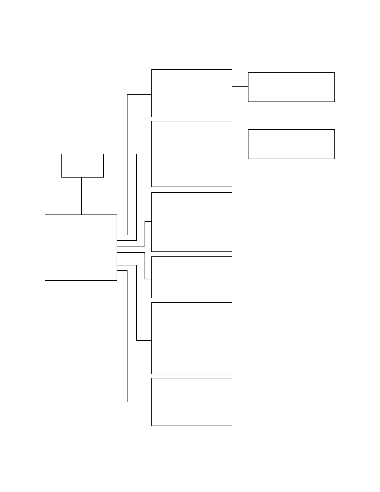
5.1 TROUBLESHOOTING FLOW CHART
26 Pelco Manual C1000M-B (1/96)
Page 31

6.0 SPECIFICATIONS
GENERAL
MODELS
ICI1000SI Single register interface with inter-
nal keypad for programming; one (1)
alarm output and thirty (30) programmable exceptions
ICI1000SE Same as ICI1000SI except with ex-
ternal keypad for programming
ELECTRICAL
Input Voltage: 5 VDC ±3%
Power Supply:
Input 120 VAC @ 15 watts, 60 Hz
Output 5 VDC @ 1 amp
Fuse Protection: 1 amp
Video Inputs: One 75 ohm NTSC/PAL
Video Outputs: One 75 ohm NTSC/PAL
Alarm Outputs: One open collector output optically
isolated to 3000V
Ambient Operating
Temperature: 35° to 95°F (12.725° to 35°C)
Dimensions: 1.5"H x 4.75"W x 8.75"L
(3.81 cm x 12.07 cm x 22.23 cm)
Weight: 2 lbs (.9 kg)
Construction: Steel, black enamel
Connectors:
Video 2 BNC
Alarm Out One open collector output
Rating: NEMA 1
Internal Composite
Synchronization:
Standard
NTSC Vertical 60 Hz @ 260 µs
Horizontal 15.36 KHz @ 4.38 µs
or
Optional PAL Vertical 50 Hz @ 260 µs
Horizontal 15.36 KHz @ 4.38 µs
Pelco Manual C1000M-B (1/96) 27
Page 32

7.0 WARRANTY AND RETURN
INFORMATION
WARRANTY
Pelco will repair or replace, without charge, any merchandise proved
defective in material or workmanship for a period of one year after the date
of shipment.
Exceptions to this warranty are as noted below:
• Five years on FT/FR8000 Series fiber optic products.
• Three years on Genex
keyboard).
• Three years on Camclosure
CC3701H-2, CC3701H-2X, CC3751H-2, CC3651H-2X, MC3651H-2,
and MC3651H-2X camera models, which have a five-year warranty.
• Two years on standard motorized or fixed focal length lenses.
• Two years on Legacy
DF5/DF8 Series fixed dome products.
• Two years on Spectra
ing when used in continuous motion applications.
• Two years on Esprit
wiper blades).
• Eighteen months on DX Series digital video recorders, NVR300
Series network video recorders, and Endura
network-based video products.
• One year (except video heads) on video cassette recorders (VCRs).
Video heads will be covered for a period of six months.
• Six months on all pan and tilts, scanners or preset lenses used in
continuous motion applications (that is, preset scan, tour and auto scan
modes).
Pelco will warrant all replacement parts and repairs for 90 days from the
date of Pelco shipment. All goods requiring warranty repair shall be sent
freight prepaid to Pelco, Clovis, California. Repairs made necessary by
reason of misuse, alteration, normal wear, or accident are not covered
under this warranty.
Pelco assumes no risk and shall be subject to no liability for damages or
loss resulting from the specific use or application made of the Products.
Pelco’s liability for any claim, whether based on breach of contract,
negligence, infringement of any rights of any party or product liability,
relating to the Products shall not exceed the price paid by the Dealer to
Pelco for such Products. In no event will Pelco be liable for any special,
incidental or consequential damages (including loss of use, loss of profit
and claims of third parties) however caused, whether by the negligence
of Pelco or otherwise.
The above warranty provides the Dealer with specific legal rights. The
Dealer may also have additional rights, which are subject to variation from
state to state.
If a warranty repair is required, the Dealer must contact Pelco at (800) 2899100 or (559) 292-1981 to obtain a Repair Authorization number (RA),
and provide the following information:
1. Model and serial number
2. Date of shipment, P.O. number, Sales Order number, or Pelco invoice
number
3. Details of the defect or problem
If there is a dispute regarding the warranty of a product which does not fall
under the warranty conditions stated above, please include a written
explanation with the product when returned.
Method of return shipment shall be the same or equal to the method by
which the item was received by Pelco.
®
Series products (multiplexers, server, and
®
and fixed camera models, except the
®
, CM6700/CM6800/CM9700 Series matrix, and
®
, Esprit®, ExSite™, and PS20 scanners, includ-
®
and WW5700 Series window wiper (excluding
™
Series distributed
RETURNS
In order to expedite parts returned to the factory for repair or credit, please
call the factory at (800) 289-9100 or (559) 292-1981 to obtain an
authorization number (CA number if returned for credit, and RA number
if returned for repair).
All merchandise returned for credit may be subject to a 20% restocking
and refurbishing charge.
Goods returned for repair or credit should be clearly identified with the
assigned CA or RA number and freight should be prepaid. Ship to the
appropriate address below.
If you are located within the continental U.S., Alaska, Hawaii or Puerto
Rico, send goods to:
If you are located outside the continental U.S., Alaska, Hawaii or Puerto
Rico and are instructed to return goods to the USA, you may do one of the
following:
If the goods are to be sent by a COURIER SERVICE, send the goods to:
Service Department
Pelco
3500 Pelco Way
Clovis, CA 93612-5699
Pelco
3500 Pelco Way
Clovis, CA 93612-5699 USA
If the goods are to be sent by a FREIGHT FORWARDER, send the goods
to:
Pelco c/o Expeditors
473 Eccles Avenue
South San Francisco, CA 94080 USA
Phone: 650-737-1700
Fax: 650-737-0933
Pelco, the Pelco logo, Camclosure, Esprit,
Genex, Legacy, and Spectra are registered
trademarks of Pelco.
Endura and ExSite are trademarks of Pelco.
© Copyright 1996, Pelco. All rights reserved.
28 Pelco Manual C1000M-B (1/96)
Page 33

APPENDIX A. HEXADECIMAL, DECIMAL AND BINARY CONVERSION TABLES
HEX Decimal Binary HEX Decimal Binary
0 0 00000000
1 1 00000001
2 2 00000010
3 3 00000011
4 4 00000100
5 5 00000101
6 6 00000110
7 7 00000111
8 8 00001000
9 9 00001001
A 10 00001010
B 11 00001011
C 12 00001100
D 13 00001101
E 14 00001110
F 15 00001111
10 16 00010000
11 17 00010001
12 18 00010010
13 19 00010011
14 20 00010100
15 21 00010101
16 22 00010110
17 23 00010111
18 24 00011000
19 25 00011001
1A 26 00011010
1B 27 00011011
1C 28 00011100
1D 29 00011101
1E 30 00011110
1F 31 00011111
20 32 00100000
21 33 00100001
22 34 00100010
23 35 00100011
24 36 00100100
25 37 00100101
26 38 00100110
27 39 00100111
28 40 00101000
29 41 00101001
2A 42 00101010
2B 43 00101011
2C 44 00101100
2D 45 00101101
2E 46 00101110
2F 47 00101111
30 48 00110000
31 49 00110001
32 50 00110010
33 51 00110011
34 52 00110100
35 53 00110101
36 54 00110110
37 55 00110111
38 56 00111000
39 57 00111001
3A 58 00111010
3B 59 00111011
3C 60 00111100
3D 61 00111101
3E 62 00111110
3F 63 00111111
40 64 01000000
41 65 01000001
42 66 01000010
43 67 01000011
44 68 01000100
45 69 01000101
46 70 01000110
47 71 01000111
48 72 01001000
49 73 01001001
4A 74 01001010
4B 75 01001011
4C 76 01001100
4D 77 01001101
4E 78 01001110
4F 79 01001111
50 80 01010000
51 81 01010001
52 82 01010010
53 83 01010011
54 84 01010100
55 85 01010101
56 86 01010110
57 87 01010111
58 88 01011000
59 89 01011001
5A 90 01011010
5B 91 01011011
5C 92 01011100
5D 93 01011101
5E 94 01011110
5F 95 01011111
60 96 01100000
61 97 01100001
62 98 01100010
63 99 01100011
Pelco Manual C1000M-B (1/96) 29
Page 34

HEX Decimal BinaryHEX Decimal Binary
64 100 01100100
65 101 01100101
66 102 01100110
67 103 01100111
68 104 01101000
69 105 01101001
6A 106 01101010
6B 107 01101011
6C 108 01101100
6D 109 01101101
6E 110 01101110
6F 111 01101111
70 112 01110000
71 113 01110001
72 114 01110010
73 115 01110011
74 116 01110100
75 117 01110101
76 118 01110110
77 119 01110111
78 120 01111000
79 121 01111001
7A 122 01111010
7B 123 01111011
7C 124 01111100
7D 125 01111101
7E 126 01111110
7F 127 01111111
80 128 10000000
81 129 10000001
82 130 10000010
83 131 10000011
84 132 10000100
85 133 10000101
86 134 10000110
87 135 10000111
88 136 10001000
89 137 10001001
8A 138 10001010
8B 139 10001011
8C 140 10001100
8D 141 10001101
8E 142 10001110
8F 143 10001111
90 144 10010000
91 145 10010001
92 146 10010010
93 147 10010011
94 148 10010100
95 149 10010101
96 150 10010110
97 151 10010111
98 152 10011000
99 153 10011001
9A 154 10011010
9B 155 10011011
9C 156 10011100
9D 157 10011101
9E 158 10011110
9F 159 10011111
A0 160 10100000
A1 161 10100001
A2 162 10100010
A3 163 10100011
A4 164 10100100
A5 165 10100101
A6 166 10100110
A7 167 10100111
A8 168 10101000
A9 169 10101001
AA 170 10101010
AB 171 10101011
AC 172 10101100
AD 173 10101101
AE 174 10101110
AF 175 10101111
B0 176 10110000
B1 177 10110001
B2 178 10110010
B3 179 10110011
B4 180 10110100
B5 181 10110101
B6 182 10110110
B7 183 10110111
B8 184 10111000
B9 185 10111001
BA 186 10111010
BB 187 10111011
BC 188 10111100
BD 189 10111101
BE 190 10111110
BF 191 10111111
C0 192 11000000
C1 193 11000001
C2 194 11000010
C3 195 11000011
C4 196 11000100
C5 197 11000101
C6 198 11000110
C7 199 11000111
30 Pelco Manual C1000M-B (1/96)
Page 35

HEX Decimal Binary HEX Decimal Binary
C8 200 11001000
C9 201 11001001
CA 202 11001010
CB 203 11001011
CC 204 11001100
CD 205 11001101
CE 206 11001110
CF 207 11001111
D0 208 11010000
D1 209 11010001
D2 210 11010010
D3 211 11010011
D4 212 11010100
D5 213 11010101
D6 214 11010110
D7 215 11010111
D8 216 11011000
D9 217 11011001
DA 218 11011010
DB 219 11011011
DC 220 11011100
DD 221 11011101
DE 222 11011110
DF 223 11011111
E0 224 11100000
E1 225 11100001
E2 226 11100010
E3 227 11100011
E4 228 11100100
E5 229 11100101
E6 230 11100110
E7 231 11100111
E8 232 11101000
E9 233 11101001
EA 234 11101010
EB 235 11101011
EC 236 11101100
ED 237 11101101
EE 238 11101110
EF 239 11101111
F0 240 11110000
F1 241 11110001
F2 242 11110010
F3 243 11110011
F4 244 11110100
F5 245 11110101
F6 246 11110110
F7 247 11110111
F8 248 11111000
F9 249 11111001
FA 250 11111010
FB 251 11111011
FC 252 11111100
FD 253 11111101
FE 254 11111110
FF 255 11111111
Pelco Manual C1000M-B (1/96) 31
Page 36

APPENDIX B. ICI1000PIM SWITCH SETTINGS
Installation instructions for configuring the ICI1000PIM
interface module are provided under separate cover in
manual C1005M-D.
If for some reason this manual is not readily available,
refer to the following section to configure the switch
settings on the PIM interface module, if applicable to
your installation.
DESCRIPTION
The following describes the DIP switch settings for
banks #1 and #2 on the ICI1000PIM interface module
(refer to Figure 9).
SWITCH BANK #1
The switches in this bank serve several different
purposes. Some basic features include Polling or Nonpolling selections, PIM addressing, clock signal
manipulation and ICI1000PIM graphics mode select.
Switch 1 Selects either a non-inverting or
inverted clock signal. The position
of this switch will vary between
registers. The switch setting varies
depending on the cash register
selected in the register decode list for
SWITCH BANK 2.
Switch 2 Selects either Polling or Non-polling
operation. Polling mode is used only
with the ICI3000P unit (Party-line
configuration) and is defined with a
[–] switch setting. Non-polling mode
should be selected when using Pelco’s
ICI2000D or ICI1000S series products
(stand-alone configuration). This
mode is defined with a [+] switch
setting.
Switch 3 This is a dual function switch
depending on the register type used.
In dot matrix cash register
applications, this switch selects either
NORMAL [–] or PIM GRAPHICS
[+] mode. Other applications will
choose between either receipt or
journal information for monitor
display. Function of this switch are
shown on the page 3. This switch is
normally in the CLOSED [–]
position.
Switches 4-8 These switches are used to set
addresses of multiple PIM’s in a
Party-line system (ICI3000P unit).
The address selected normally
coincides with the actual cash
register number. The appropriate
switch settings for corresponding
PIM addresses are shown below.
SWITCH # POLLING PIM ADDRESS
45678 (PIM #)
– –––– 1
–––– + 2
––– + – 3
–––+ + 4
–– + –– 5
– – + – + 6
– – + + – 7
– – + + + 8
– + – – – 9
– + – – + 10
– + – + – 11
– + – + + 12
– + + – – 13
– + + – + 14
– + + + – 15
– + + + + 16
+ –––– 17
+ – – – + 18
+ – – + – 19
+ – – + + 20
+ – + – – 21
+ – + – + 22
+ – + + – 23
+ – + + + 24
+ + – – – 25
+ + – – + 26
+ + – + – 27
+ + – + + 28
+ + + – – 29
+ + + – + 30
+ + + + – 31
+ + + + + 32
NOTE:
[–] indicates an UP switch position
[+] indicates a DOWN switch position
In other words, a [–] means that you need to
slide the switch towards the [–] position on
the switch. Refer to the Figure 9 for a
definition of [–] and [+] positions.
32 Pelco Manual C1000M-B (1/96)
Page 37

SWITCH BANK #2
X = POLLING/NON-POLLING
[+] NON-POLLING
This switch is dedicated to selecting which type of cash
[–] POLLING (Refer to page 35.)
register the ICI1000PIM is interfacing with. The table
below indicates the appropriate switch settings for a
particular cash register. The first three settings indicate
the appropriate settings for switches 1-3 on switch bank
R = RECEIPT
[–] or JOURNAL
[+] SELECT (Normally CLOSED [–])
#1. A more detailed description of these three switches
can be found at the beginning of this section.
G = GRAPHICS (Normally CLOSED [–])
+ = OPEN - FLIP THE SWITCH DOWN
IMPORTANT : The information below ap-
– = CLOSED - FLIP THE SWITCH UP
plies to the ICI1000PIM versions 4.02 and
greater only .
Register Bank #1 Bank #2
Type Switch # Switch #
Selection 1 2 3 1 2 3 4 5 6 7 8
CASIO TK-2000 Dot Matrix Printer .................................................................................. + X G - - - + + + - -
CASIO TK4300 Dot Matrix Printer ................................................................................... + X G - - - + + + + -
CASIO TK1200/TK2600/TK4600/CE4115/CE4630 Dot Matrix Printer ............................ + X G - - - + + - + +
CASIO TK2100/CE4530 Dot Matrix Printer ..................................................................... + X G - - - + + + - +
CASIO SA2000/2100 - Serial Printer ................................................................................ + X - - - - + + + + +
DATA CHECKER ALPHA 2/3 Printer, ICL MT20001 With Alpha 2/3 Printer....................+ X R + - - + - - + -
DRESSER WAYNE Printer Serial.....................................................................................+ X R + - - - + + + -
ESPER 7100 Drum Printer................................................................................................ + X - + - - + + - - -
ESPER 7540/7810 Dot Matrix Printer .............................................................................. + X G + - - + + - - +
FUGITSU/ATRIUM Series with Bar 200 Printer................................................................+ X R + - - + - - - -
GILBARCO TCR/G2 Parallel Printer .................................................................................- X G - - - - - - - -
HUGEN SWEDA - SWEDA 5436 Serial Printer ................................................................ + X - + - - - - + - -
IBM Model 1/2 Printer, IBM4683/4684 With Model 1 OR Model 2 Printer ........................+ X R + - - + - - + +
IBM Model 3&4 Printer, IBM4683/4684 IBM4693/4694 With Model 3 Printer...................+ X R + - - + - + - -
ICL-200 PTR, ICL-STORE MASTER 9518-200 ................................................................+ X R + - - + - - - -
ICL/DATA CHECKER MDL - 1600,1700,1800 Multidrop Connection ............................... + X - + - - + - - - +
ICL/DTS 2000/2100/2200 EPSON 220-AF Dot Matrix Printer ........................................ + X G - - + - - - - -
ICL/DTS 2000/2100/2200 EPSON 220-F Dot Matrix Printer ........................................... + X G - - + - - - - +
JCM GOLD 2200 Drum Printer ......................................................................................... + X - + - - + - + + -
NCR 2127 With V3 MULTIFINCITON Printer - Serial ....................................................... + X - - - - + + - + -
NCR 2121 Printer - Serial ................................................................................................. + X + - - - + + - - +
NCR 2113 Printer - Serial ................................................................................................. + X - - - - + + - - -
NCR ANSWER Printer SINGLE
NCR 1255/2140/2151/2152/2154/2157/2160/2552/2557
NCR 5300/SASI 1028/OLD STYLE Printer/MERIT REGISTER SYSTEMS ................. - X R - - - + - + - -
NCR ANSWER Printer DUAL - NCR 2126 ....................................................................... - X R - - - + - + - +
NCR 7150-5001 Printer (7000 SERIES REG.) ................................................................. + X R - - - + - + + -
Pelco Manual C1000M-B (1/96) 33
Page 38

Register Bank #1 Bank #2
Type Switch # Switch #
Selection 1 2 3 1 2 3 4 5 6 7 8
NIXDORF .......................................................................................................................... + X + + - - + + + + +
OMRON RS5550/RS5560 Dot Matrix Printer ................................................................... - X G - - + - - - + -
OMRON 4510, 4541 Dot Matrix Printer .............................................................................- X - - - + - - - + +
OMRON RS3410 Dot Matrix Printer ................................................................................. - X G + - - - - + - +
OMRON 4041, 4043 Dot Matrix Printer ............................................................................ + X - - - + - - + - -
PANASONIC JS-6500 Dot Matrix Printer .......................................................................... - X G + - - + + - + +
RCALLEN RC204 Drum Printer ........................................................................................ + X - + - - + - + + +
SAMSUNG 4900, 4915, 4950 Dot Matrix Printer .............................................................. - XG - - + - - + + -
SANYO ECR 580,690,720 EPSON 220F Dot Matrix Printer ........................................... + X G + - - + + - + -
SHARP A430 DP630 Dot Matrix Printer ........................................................................... - X G - - + - - + - +
SHARP 2381/2391 Drum Printer ...................................................................................... + X + - - - - - - + -
SHARP 3230/3231/3240/3241/4230/4231 Dot Matrix Printer ........................................... - X G - - - - - + - +
SHARP 3100/3100S/3110/3250/3252/3300/3310/3311 Dot Matrix Printer ...................... - X G - - - - - + + -
SHARP 4230, 4231 Dot Matrix Printer.............................................................................. - XG + - + - - - - -
SHARP 2595 Drum Printer ............................................................................................... + X + - - - - - + - -
SHARP 2385/2386/2395/2396 Drum Printer .................................................................... + X + - - - - - - + +
SHARP A550 Dot Matrix Printer ...................................................................................... + X G - - - - + - - -
SHARP 3220 Dot Matrix Printer........................................................................................- X G - - - - - + + +
SHARP 2540/2590/2590S Drum Printer ........................................................................... + X + - - - - - - - +
SWEDA 2810/OMRON RS14-30 (USA Type) Drum Printer.............................................+ X + + - - - - - - -
SWEDA 2810/OMRON RS14-40 (USA Type) Drum Printer.............................................+ X + + - - - - - - +
SWEDA 2810/OMRON RS14-40 (European Type) Drum Printer ..................................... + X + + - - - - - + -
SWEDA 2820/OMRON XXXX-XX (USA Type) Drum Printer ........................................... + X + + - - - - - + +
SWEDA 2860 .................................................................................................................... - X G + - - + + + - +
TEC 136/141/191/196 DISPLAY ....................................................................................... - X + - - - - + - - +
TEC 206/216/227/230/290 DISPLAY ................................................................................ - X + - - - - + - + -
TEC 141 Printer Drum Printer ........................................................................................... + X + - - - - + - + +
TEC 132/145 Drum Printer................................................................................................ + X - + - - + - + - +
TEC 2200/2300/2600 DPR-610/620 Dot Matrix Printer ................................................... + X G - - - - + + - -
TEC 2200/2300/2600 DPR-630 Dot Matrix Printer .......................................................... + X G - - - - + + - +
TEC 2200/2300/2600 DPR-61A Dot Matrix Printer.......................................................... + X G - - - - + + + -
TEC 1050/1060/1100/1190 DPR-710 Dot Matrix Printer .................................................. - X G - - - - + + + +
TEC 1050/1060/1100/1190 DPR-730 Dot Matrix Printer .................................................. - X G - - - + - - - -
TEC 1400/1600/1700/1900/FDS-30 DPR-370/374 Dot Matrix Printer ............................. + X G - - - + - - - +
TEC 1400/1600/1700/1900/FSD-30 DPR-370S Dot Matrix Printer ................................. + X G - - - + - - + -
TEC FT77 Printer - Serial Interface................................................................................... + X - - - - + - - + +
TOKHEIM .......................................................................................................................... - X R + - - + + + - -
34 Pelco Manual C1000M-B (1/96)
Page 39

Figure 9. ICI1000PIM Switch Settings
ICI1000PIM INSTALLATION/
TROUBLESHOOTING GUIDELINES
Listed below are some simple troubleshooting steps at
your disposal. Following these steps will ensure that
your Inter-Check P.O.S. unit is communicating correctly
with your ICI1000PIM module.
1. Always execute a PIM DEF AUL T LOAD (DL) on
your Inter-Check unit. Pelco suggests the use of
the Default Load even if your installation does not
require a PIM module. The Default Load sets all
Inter-Check communication parameters to the specific values needed to communicate with your
ICI1000PIM module.
2. Select cash register options using the switch banks
on your PIM. Refer to previous pages for more
information.
NOTE: In rare instances when connecting a
PIM directly to an ICI1000S unit is desired
(without the use of a wiring kit), the data cable
will need to be modified.
To modify the cable:
a. Slit the gray insulation jacket of the data cable
and expose the internal wires.
b.Cut the red and green wires and remove a
small section of each to prevent against accidental contact.
4. Install the PIM into the cash register. Refer to the
installation instructions included with your particular cash register interface.
5. Power-up PIM and look for prompt again.
3. Utilizing the wiring kit, perform a bench test by
connecting the PIM to the Inter-Check unit and then
power up the PIM. Upon power-up, you should
see a prompt scroll across the monitor which
matches your register type. A PIM version number
will also be displayed. If this prompt appears on
the monitor, the Inter-Check unit and PIM are communicating properly.
Now, install the wiring kit and connect the PIM
according to the proper wiring shown in Figure 2
and power up the PIM again. If the wiring is correct, you should see the prompt explained in step
#3.
Pelco Manual C1000M-B (1/96) 35
6. Power-up cash register and test for proper operation.
Page 40

®
Pelco
3500 Pelco Way, Clovis, CA 93612-5699 (209) 292-1981 • (800) 289-9100
FAX (800) 289-9150 or (209) 292-3827
(Product specifications subject to change without notice.)
C1000M-B
36 Pelco Manual C1000M-B (1/96)
 Loading...