

Page 1

C2295M-B-EN (12/16)
IBP122-1I
IBP222-1I
IBP322-1I
IBP124-1I
IBP224-1I
IBP324-1I
IBP121-1I
IBP221-1I
IBP321-1I
IBP521-1I
IBP122-1R
IBP222-1R
IBP322-1R
IBP124-1R
IBP224-1R
IBP324-1R
IBP121-1R
IBP221-1R
IBP321-1R
IBP521-1R
Sarix
®
Professional IBP
Series Environmental IR
Bullet & Indoor Bullet
Camera
Quick Start Guide
Page 2

Contents
Contents ....................................................................................................................................................................................... 2
Important Notices Statement ........................................................................................................................................................ 3
Regulatory Notices ......................................................................................................................................................... 3
Radio and Television Interference ................................................................................................................................. 3
Korean Class A EMC ............................................................................................................................................................ 3
Warranty Statement ..................................................................................................................................................................... 3
UL Safety Notices .......................................................................................................................................................... 3
Models Instructions ...................................................................................................................................................................... 4
Description ................................................................................................................................................................................... 5
Package Contents ........................................................................................................................................................................ 5
Installation .................................................................................................................................................................................... 5
Wall Surface Mount ........................................................................................................................................................ 6
- With IBP2BBAP-ES .............................................................................................................................................. 7
In-Ceiling Installation ...................................................................................................................................................... 8
Applying Rubber Seal Plug ............................................................................................................................................ 8
Adjusting The Protection Shield Hood ........................................................................................................................... 9
Position the Camera ...................................................................................................................................................... 9
Adjusting the Focus ....................................................................................................................................................... 9
Pelco Troubleshooting Contact Information ............................................................................................................................... 10
Note for Dimension Drawings ..................................................................................................................................................... 10
2
Page 3

Important Notices Statement
For information about Pelco’s product-specific important notices and thereto related information, refer to www.pelco.com/legal.
REGULATORY NOTICES
This device complies with Part 15 of the FCC Rules. Operation is subject to the following two conditions: (1) this device may
not cause harmful interference, and (2) this device must accept any interference received, including interference that may
cause undesired operation.
RADIO AND TELEVISION INTERFERENCE
This equipment has been tested and found to comply with the limits of a Class A digital device, pursuant to Part 15 of the FCC
rules. These limits are designed to provide reasonable protection against harmful interference when the equipment is operated
in a commercial environment. This equipment generates, uses, and can radiate radio frequency energy and, if not installed
and used in accordance with the instruction manual, may cause harmful interference to radio communications. Operation of
this equipment in a residential area is likely to cause harmful interference in which case the user will be required to correct the
interference at his own expense.
Changes and Modifications not expressly approved by the manufacturer or registrant of this equipment can void your authority
to operate this equipment under Federal Communications Commission’s rules.
CAN ICES-3(A)/NMB-3(A)
Korean Class A EMC
Warranty Statement
For information about Pelco’s product warranty and thereto related information, refer to www.pelco.com/warranty.
UL SAFETY NOTICES
The product is intended to be supplied by a Listed Power Unit marked "L.P.S." (or "Limited Power Source") and rated output
24Vac, 50/60Hz, 1.28A minimum or 48Vdc, 0.35A minimum.
The product shall be installed by a qualified service person and the installation shall conform to all local codes.
3
Page 4

Models Instructions
Model
Description
IBP122-1I
SRX PRO2 IND BULLET POE24V12V 1MP 9-22MM D/N LENS
IBP222-1I
SRX PRO2 IND BULLET POE24V12V 2MP 9-22MM D/N LENS
IBP322-1I
SRX PRO2 IND BULLET POE24V12V 3MP 9-22MM D/N LENS
IBP124-1I
SRX PRO2 IND BULLET POE24V12V 1MP 12-40MM D/N LENS
IBP224-1I
SRX PRO2 IND BULLET POE24V12V 2MP 12-40MM D/N LENS
IBP324-1I
SRX PRO2 IND BULLET POE24V12V 3MP 12-40MM D/N LENS
IBP121-1I
SRX PRO2 IND BULLET POE24V12V 1MP 3-10MM D/N LENS
IBP221-1I
SRX PRO2 IND BULLET POE24V12V 2MP 3-10MM D/N LENS
IBP321-1I
SRX PRO2 IND BULLET POE24V12V 3MP 3-10MM D/N LENS
IBP521-1I
SRX PRO2 IND BULLET POE24V12V 5MP 3-10MM D/N LENS
IBP122-1R
SRX PRO2 ENV BULLET POE24V12V 1MP 9-22MM D/N LENS
IBP222-1R
SRX PRO2 ENV BULLET POE24V12V 2MP 9-22MM D/N LENS
IBP322-1R
SRX PRO2 ENV BULLET POE24V12V 3MP 9-22MM D/N LENS
IBP124-1R
SRX PRO2 ENV BULLET POE24V12V 1MP 12-40MM D/N LENS
IBP224-1R
SRX PRO2 ENV BULLET POE24V12V 2MP 12-40MM D/N LENS
IBP324-1R
SRX PRO2 ENV BULLET POE24V12V 3MP 12-40MM D/N LENS
IBP121-1R
SRX PRO2 ENV BULLET POE24V12V 1MP 3-10MM D/N LENS
IBP221-1R
SRX PRO2 ENV BULLET POE24V12V 2MP 3-10MM D/N LENS
IBP321-1R
SRX PRO2 ENV BULLET POE24V12V 3MP 3-10MM D/N LENS
IBP521-1R
SRX PRO2 ENV BULLET POE24V12V 5MP 3-10MM D/N LENS
The physical appearances and installation methods for the models indicated within the list below are, by and large, the same.
Therefore, please use this quick guide where we take the example from IBP521-1RS as a reference to apply to all the varied
models.
4
Page 5

Description
The Sarix® Professional Series IP Bullet is ideal for both indoor and outdoor applications, based on IR or Non-IR type. Before
installing it, please verify your model and read this guide carefully
Package Contents
Environmental IR Bullet camera / Indoor Bullet camera * 1
Plastic Anchor * 4
Flat Head Screw (Tapping Type) * 4
Rubber Seal Plug * 1
T20 Security Torx Wrench * 1
T10 Security Torx Wrench * 1
Mounting Template * 1
Important Notices Declaration * 1
Printed Quick Start Guide * 1
Supplemental Resources Sheet * 1
Important Safety Instruction * 1
ROHS Statement Slip * 1
Optional Accessories
IBP2BBAP-ES: a Sarix Environmental Surface mount for Bullet
IBP2BBAP-EI: a Sarix Environmental In-Ceiling Mount for Bullet
Installation
Sarix® Professional Series IP Bullet Camera can be installed by the following methods.
Wall Surface Mount
In-Ceiling Mount (refer to In-Ceiling Installation)
5
Page 6
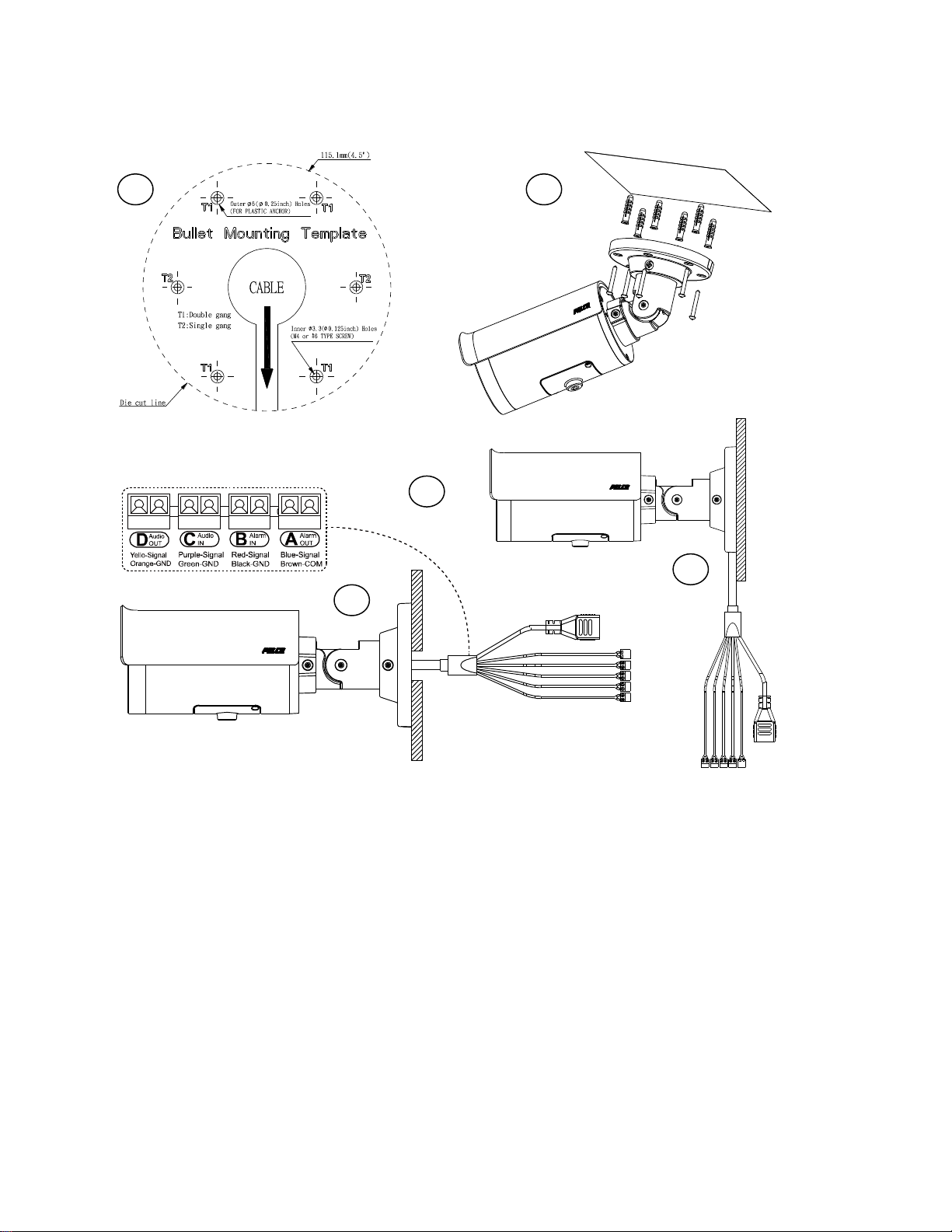
WALL SURFACE MOUNT
1
3 2 I
II
Install the indoor bullet / environmental IR bullet camera to a wall surface as shown in the following procedure.
1. Drill 6 mm (0.25”) outer holes based on the mounting template and hammer the plastic anchors into the holes.
2. Pass all the cable thread through the bracket and all the way to the mounting hole (I) or pass the cable thread through
the side hole of the bracket (II) according to your application.
Connect the required power cable by the following options:
24 VAC: Connect 24V (~) cables to terminals ~24 VAC (Black & Red cables)
12 VDC: Connect 12V cables to terminals ~12 VAC (Black & Red cables)
PoE: Connect an Ethernet cable terminated with RJ-45 connector that connects with a PoE compatible network device
NOTE: To avoid damage to the camera, never connect more than one type of power supply (PoE IEEE802.3
Ethernet Class 3 or AC 24V or DC 12V power plug) at the same time.
Further connect digital IO cables if necessary. Refer to below for details.
Alarm Out (A): Using the “Signal (Blue)” and “COM (Brown)” ports, connect to an external alarm output device.
Alarm In (B): Using the “Signal (Red)” and “GND (Black)” ports, connect to an external alarm input device.
Audio In (C): Using the “Signal (Purple)” and “GND (Green)“ ports, connect to an external audio input device.
Audio Out (D): Using the “Signal (Yellow)” and “GND (Orange)“ ports, connect to an external audio output device.
3. Tighten the camera onto the surface by fixing the included tapping screws securely.
6
Page 7
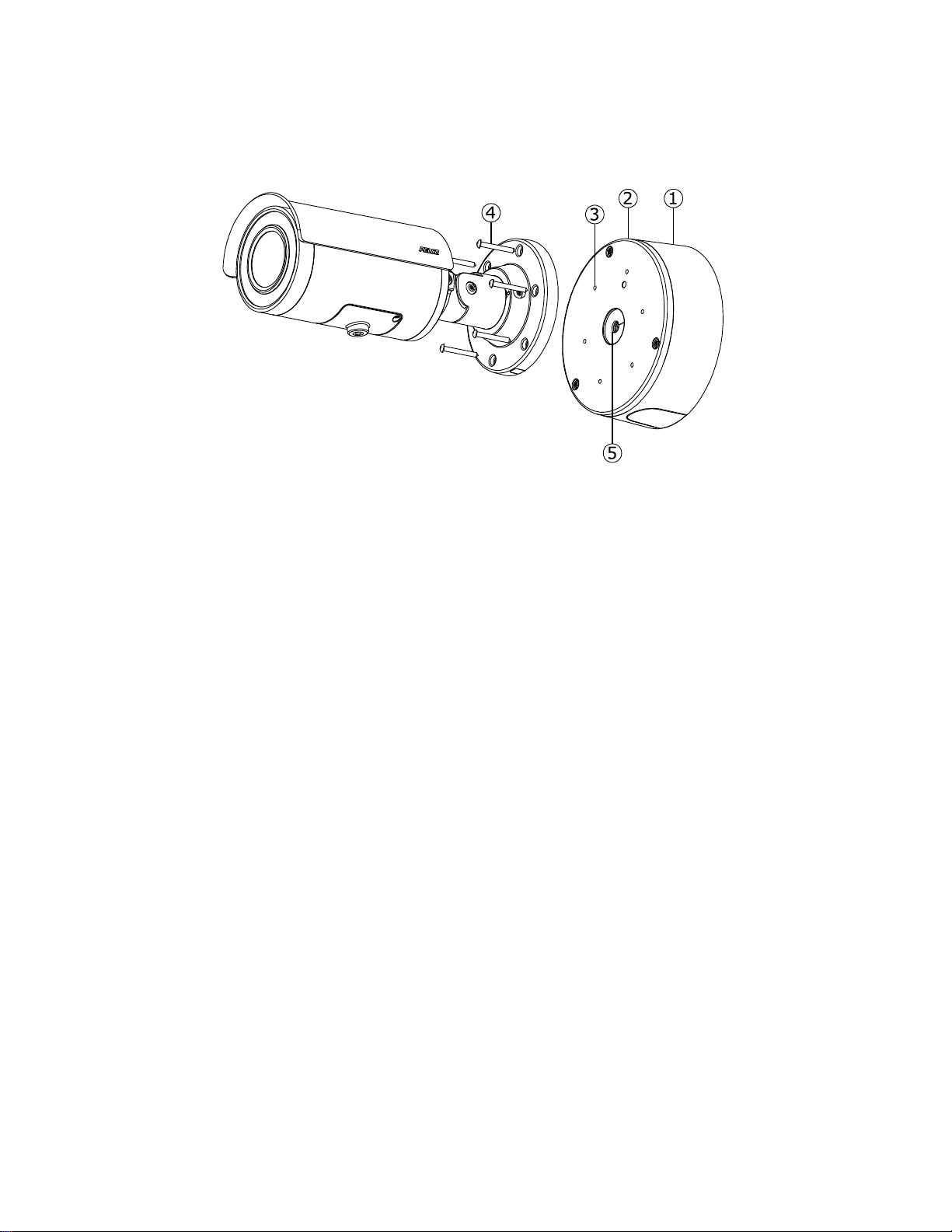
- WITH IBP2BBAP-ES
Also, you can mount the camera to the wall with IBP2BBAP-ES, a Sarix Environmental Surface
Mount for Bullet. Refer to the figure below for surface installation with IBP2BB-ES.
1. Fix the IBP2BBAP-ES back box (#1) to the desirable surface by drilling three holes and fastening it with screws.
2. Pass all the signal cables through the hole of rubber (#5), and then insert the rubber into the center hole of metal plate.
NOTE: Please identify both sides of the rubber. The side of the rubber with the inclined angle must be towards the
terminals of the cables and metal plate to avoid water leakage.
3. Install the adaptor plate(#2) in the back box and tighten the screws
4. Insert screws (#4) through the bracket’s screw holes and tighten screws into the corresponding hole (#3) of the adaptor
metal.
5. Complete surface installation with IBP2BBAP-ES.
7
Page 8
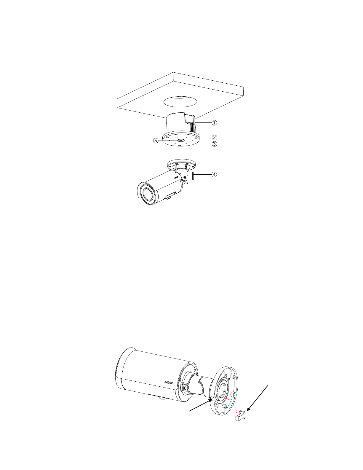
IN-CEILING INSTALLATION
Rubber Seal Plug
Side Hold of Bracket
The In-Ceiling Installation is mounting the camera into the ceiling with IBP2BBAP-EI, a Sarix Environmental In-Ceiling
Mount for Bullet. Refer to the figure below for in-ceiling installation with IBP2BBAP-EI.
1. Make a round hole for IBPBBAP-EI back box to fit in.
2. Pass all the signal cables through the hole of rubber (#5), and then insert the rubber into the center hole of metal
plate.
NOTE: Please identify both sides of the rubber. The side of the rubber with the inclined angle must be towards
the terminals of the cables and metal plate to avoid water leakage.
3. Install the adaptor plate(#2) in the back box and tighten the screws
4. Insert screws (#4) through the bracket’s screw holes and tighten screws into the corresponding hole (#3) of the
adaptor metal.
5. Complete in-ceiling installation with IBPBBAP-EI.
APPLYING RUBBER SEAL PLUG
For the scenario of cable thread through mounting hole, it is required to properly secure the rubber seal plug into the side hold
of bracket. The rubber seal plug, with anti-ingress functionality, is able to prevent liquid, e.g., rain, from invading into the
camera and thereby securely assures the stable operation of camera.
NOTE: While installing, tuck the rubber seal plug into the side hole from the rear side of the bracket as the image shown
above, so that the complete anti-ingress functionality can be positively guaranteed.
8
Page 9
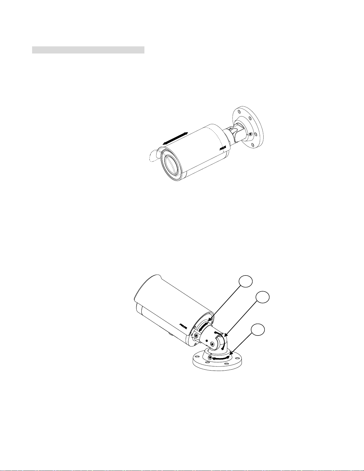
ADJUSTING THE PROTECTION SHIELD HOOD
A
B
C
Environmental IR Series Exclusive Only
The environmental IR series are designed with capability to operate under rugged environments and thus will possibly be
subject to influences from sunlight or rain. Protection shield hood is therefore coated on the camera to prevent damage from
those outside effects. To adjust the protection shield hood, move the hood forward or backward to adjust till the desired
position.
NOTE: Be sure to adjust the protection shield hood in accordance with the lens coverage in case of shadow problems
occurring. To avoid housing damage, DO NOT adjust the protection shield hood position excessively.
POSITION THE CAMERA
Retaining Ring for Pan Adjustment (A): Loosen the locking screw by T20 torx wrench and rotate the retaining ring (A) to
adjust the camera horizontally for applying to a variety of applications.
Bracket Axis for Tilt Adjustment (B): Loosen the locking screw by T20 torx wrench and tilt the bracket axis (B) to adjust
the camera vertically for applying to varied applications.
Adjustable Ring for 360°Rotation (C): Loosen the locking screw by T20 torx wrench and rotate the camera body (C) to
adjust the camera for applying to varied applications.
NOTE: Limitation for 3 axes position: Pan range: ±360°, Tilt range: 0°~ 90°, Rotation range: ±360°.
NOTE: After adjustments, make sure to tighten each part to prevent camera from moving.
ADJUSTING THE FOCUS
1. View the camera image using the browser (refer to the user manual).
2. Use the settings in the Web interface (refer to the user manual) to adjust the zoom and focus of the lens to the desired
field of view.
3. Also the focus can be adjusted by moving the zoom slider and using the Focus options in the live webpage.
NOTE: Focus adjustment is done exclusively with Web UI.
9
Page 10
Pelco Troubleshooting Contact Information
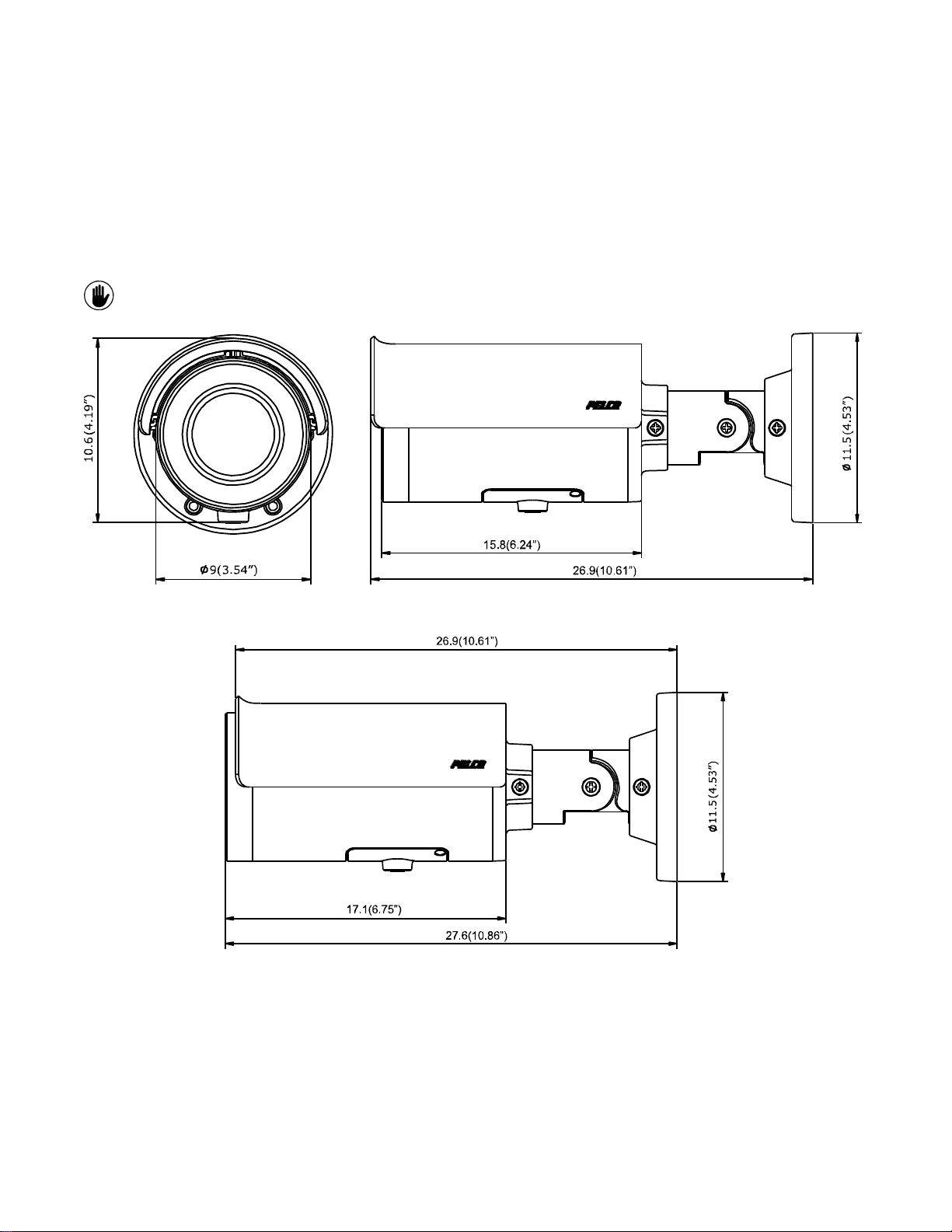
NOTE: VALUES IN PARENTHESES ARE INCHES; ALL OTHERS ARE CENTIMETERS.
ENVIRONMENTAL IR BULLET – 9-22MM / 3-10.5MM / 3.6-10MM
ENVIRONMENTAL IR BULLET – 12-40MM
ENVIRONMENTAL IR BULLET
If the instructions provided fail to solve your problem, contact Pelco Product Support at 1-800-289-9100 (USA and Canada) or
+1-559-292-1981 (international) for assistance. Be sure to have the serial number available when calling.
Do not try to repair the unit yourself. Leave maintenance and repairs to qualified technical personnel only.
Note for Dimension Drawings
10
Page 11
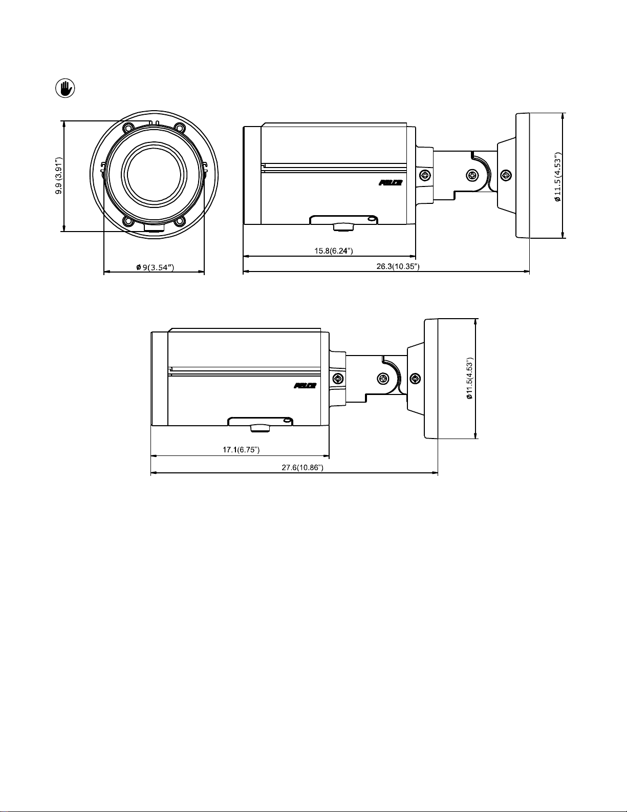
NOTE: VALUES IN PARENTHESES ARE INCHES; ALL OTHERS ARE CENTIMETERS.
INDOOR BULLET – 9-22MM / 3-10.5MM / 3.6-10MM
INDOOR BULLET – 12-40MM
INDOOR BULLET
11
Page 12

© Copyright 2016, Pelco, Inc.
All rights reserved.
12
 Loading...