

Page 1
1
IBEPLMT-E
Environmental Pole
Mount
Installation Manual
F
O
R
Page 2

2
Important Notices
For more information about Pelco’s product-specific important notices and thereto related information, refer to
www.pelco.com/legal.
REGULATORY NOTICES
This device complies with Part 15 of the FCC Rules. Operation is subject to the following two conditions: (1)
this device may not cause harmful interference, and (2) this device must accept any interference received,
including interference that may cause undesired operation.
Radio and Television Interference
This equipment has been tested and found to comply with the limits of a Class A digital device, pursuant to
Part 15 of the FCC rules. These limits are designed to provide reasonable protection against harmful
interference when the equipment is operated in a commercial environment. This equipment generates, uses,
and can radiate radio frequency energy and, if not installed and used in accordance with the instruction
manual, may cause harmful interference to radio communications. Operation of this equipment in a
residentialarea is likely to cause harmful interference in which case the user will be required to correct the
interference at his own expense.
Changes and modifications not expressly approved by the manufacturer or registrant of this equipment can
void your authority to operate this equipment under Federal Communications Commission’s rules.
CAN ICES-3(A)/NMB-3(A).
KOREAN CLASS A EMC
WARRANTY STATEMENT
For information about Pelco’s product warranty and thereto related information, refer to www.pelco.com/
warranty.
UL Safety Notices
This product is intended to be supplied by a Listed Power Unit marked “L.P.S.” (or “Limited Power Source”)
and rate output 24Vac, 50/60Hz, 1.28 minimum or 48 Vdc, 0.35A minimum.
The product shall be installed by a qualified service person and the installation shall conform to local codes.
Page 3
3
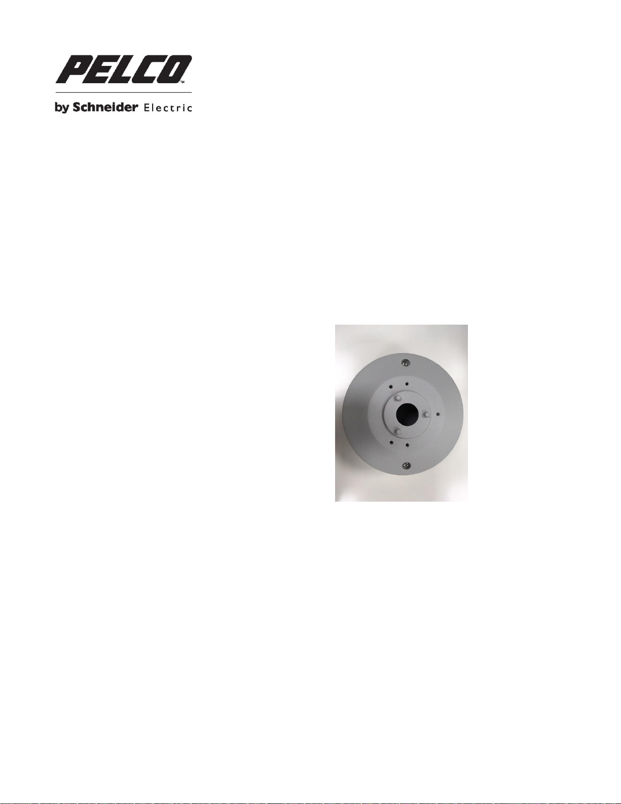
POLE MOUNT: INSTALLATION WITH ENVIRONMENTAL
(IBEPLMT-E) POLE MOUNT
Supplied Parts List
Qty Description
1 Pole mount junction box
5 M4 x 12mm machine screws
2 Stainless steel rings
NOTE: The supplied stainless steel rings apply to poles with the diameter from 70 to 180mm.
User-Supplied Parts List
Qty Description
1 Bullet camera
1 Ethernet cable
1 Power cable (necessary if PoE is not available)
1 Alarm cable (optional)
1 Audio cable (optional)
1 Phillips and flathead screwdriver
Installation Guide
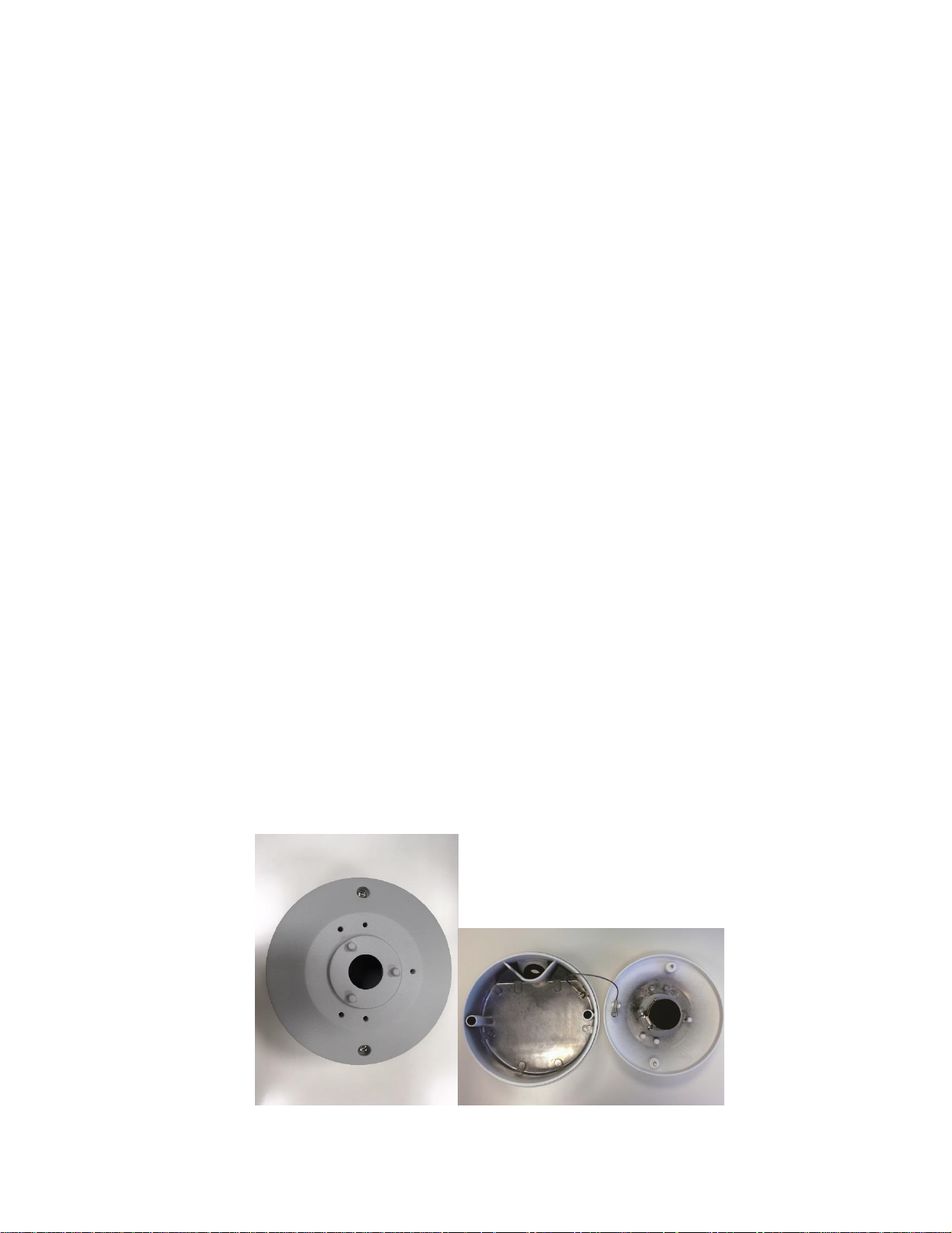
1. Loosen the two screws in the photo below and detach the pole mount junction box cover.
Page 4

4
2. Remove the internal rubber plug from the cable entry hole of the pole mount junction box cover.
3. Thread the connectors of the All-In-One cable of the camera one by one through the cable entry hole.
4. Insert the rubber plug back to the cable entry hole and use a flathead screwdriver to tighten the stainless
steel ring by turning the knob clockwise. Make sure there’s no gap between the All-In-One cable and
cable entry hole.
5. Connect the required cables (e.g. Ethernet cable) (#1 and #2 in the picture below) to the connectors of
the All-In-One cable.
Page 5

5
6. Arrange the All-In-One cable neatly.
7. Adjust the position of pole mount junction box cover properly and fasten the two screws to tighten the
cover.
NOTE: When securing the pole mount junction box cover, you must align the two arrow marks with each
other to ensure the cover is properly fixed.
8. Align the two screw holes of the camera with the screw holes on the pole mount junction box cover and
fasten the camera with the M4 machine screws. The drainage hole should point down when installing
horizontally.
Page 6

6
9. Loosen the knobs on the stainless steel rings by turning them counterclockwise with a flathead
screwdriver.
Pelco Troubleshooting Contact Information
If the instructions provided fail to solve your problem, contact Pelco Product Support at 1-800-289-9100 (USA and Canada) or
+1-559-292-1981 (international) for assistance. Be sure to have the serial number available when calling.
Do not try to repair the unit yourself. Leave maintenance and repairs to qualified technical personnel only.
Page 7

7
 Loading...