

Page 1
C421M-D (2/00)
HT10 Series
Liquid-Cooled Enclosure
®
300 W. Pontiac Way,
Clovis, CA 93612-5699
USA
In North America & Canada:
Tel (800) 289-9100
FAX (800) 289-9150
DataFAX (800) 289-9108
International Customers:
Tel +1 (559) 292-1981
FAX +1 (559) 348-1120
DataFAX +1 (559) 292-0435
Pelco Online
http://www.pelco.com
U
®
L
LISTED
IMPORTANT SAFEGUARDS AND WARNINGS
Prior to installation and use of this product, the following WARNINGS should be observed.
1. Installation and servicing should only be done by qualified service personnel and conform
to all local codes.
2. Unless the unit is specifically marked as a NEMA Type 3, 3R, 3S, 4, 4X ,6 or 6P enclosure, it is designed for indoor use only and it must not be installed where exposed to rain
and moisture.
3. Only use replacement parts recommended by Pelco.
4. After replacement/repair of this unit’s electrical components, conduct a resistance measurement between line and exposed parts to verify the exposed parts have not been connected to line circuitry.
5. The installation method and materials should be capable of supporting four times the
weight of the enclosure, pan/tilt, camera and lens combination.
6. Use or mount this enclosure so that it is positioned not less than 91 degrees and not
more than 180 degrees when considering 12 o’clock to be 0 degrees and 6 o’clock to be
180 degrees.
7. Only Nema 3R liquid tight conduit should be used in all outdoor applications.
The product and/or manual may bear the following marks:
This symbol indicates that dangerous voltage constituting a risk of
electric shock is present within
this unit.
This symbol indicates that there
are important operating and maintenance instructions in the literature accompanying this unit.
Please thoroughly familiarize yourself with the information in this manual prior to installation
and operation.
CAUTION:
RISK OF ELECTRIC SHOCK.
DO NOT OPEN.
DESCRIPTION
The products in the HT10 Series are liquid-cooled enclosures designed for high temperature
applications.
The stainless steel enclosure features two separate double-walled cooling jackets that protect
the camera and lens and other sensing devices housed within the unit.
Models
HT10V High temperature enclosure with Vycor® window; window suitable in
temperatures up to 2500°F (1371°C)
HT10V/RC Same as the HT10V except Vycor window has an infrared reflective coating
for environments where high levels of radiant heat are encountered; window
suitable in temperatures up to 1832°F (1000°C)
Page 2
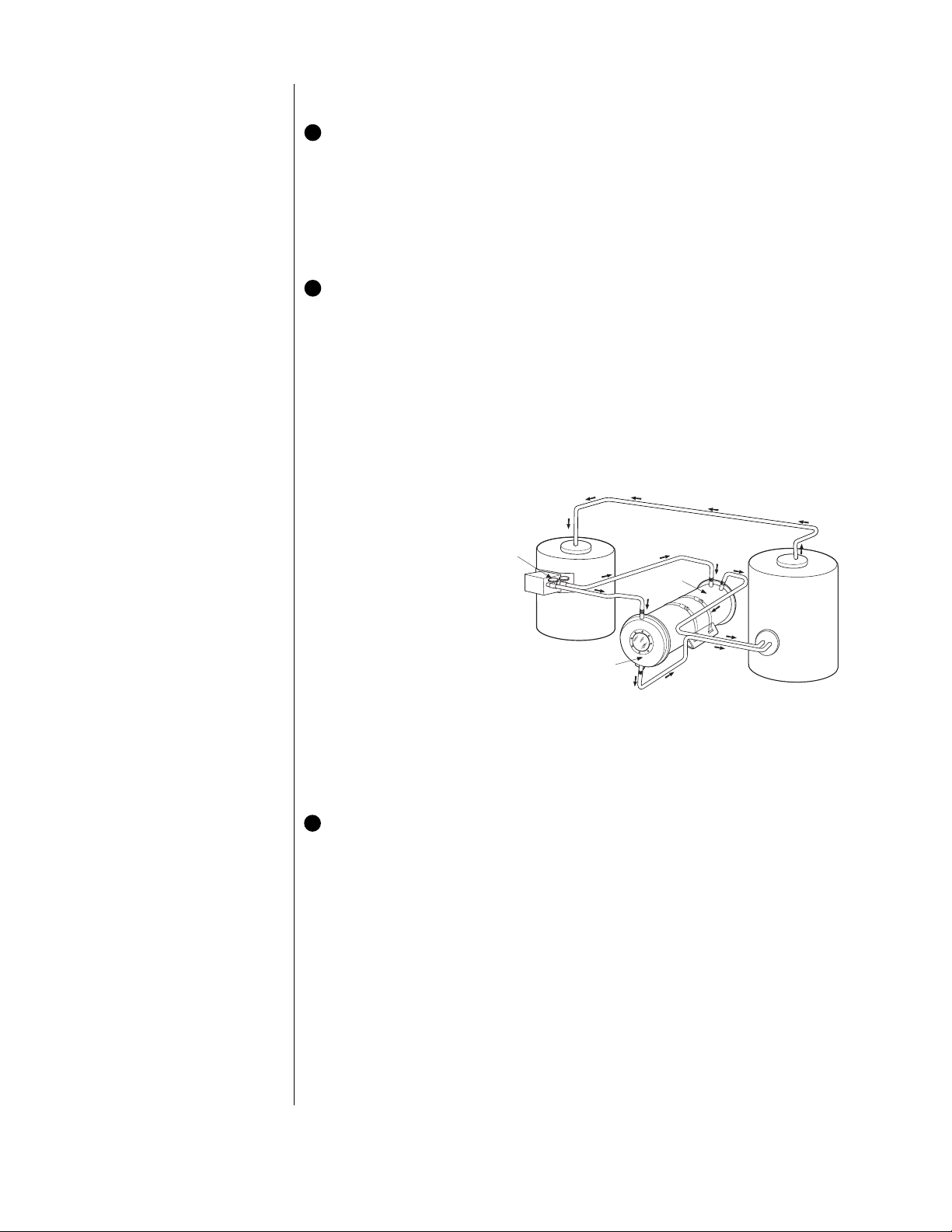
*RESERVOIR
*COOLING TANK
*SHUT OFF
VALVES
COOLING
JACKET
COOLING
JACKET
*LOCATION OF EQUIPMENT IS NOT INTENDED FOR ANY SPECIFIC APPLICATION.
NOTE:
GENERAL DIAGRAM - PUMP, INSULATION, CHECK VALVES AND TYPE OF
PLUMBING NOT SHOWN.
INSTALLATION
1 Mount the Enclosure
Determine the mounting location. Attach the enclosure as follows:
1. Remove the enclosure from the cradle by loosening the screw clamps on the stainless
steel straps.
2. Attach the cradle to the mounting surface (mount, pan/tilt, etc.).
3. Center the enclosure on the cradle and secure it with the stainless steel straps.
2 Connect Cooling Systems
The HT10 Series enclosure features two distinct cooling systems. One cooling jacket is located in the body of the unit and the other is strategically placed around the viewing window.
(Refer to Figure 1.)
To make cooling system connections:
1. Use hoses with a 3/8-inch NPT fitting (not supplied).
2. Connect the enclosure to a coolant reservoir. A shut-off valve should be installed in the
input line to regulate coolant flow.
3. Make input connections.
Input hoses are connected
to the IN line fittings
located at the top and
rear of the enclosure.
IMPORTANT:
Check coolant
flow rate periodically to ensure
that sediment or deposits are
not restricting flow. This will prevent heat from building up in the
enclosure, or steam from developing in the water jacket.
4. Make output connections.
Output hoses are connected to the OUT line
fittings located at the top
and rear of the enclosure.
The output line should not
be restricted, so that the 35
psi working pressure is not
exceeded. The liquid flow
rate is determined by the
temperature of the coolant
as it enters the enclosure
and the temperature gradient
in which the enclosure is
installed.
Figure 1. Coolant Hook-Up, General Installation
3 Install Camera
To mount the camera on the sled:
1. Remove the rear plate of the enclosure.
2. Remove the camera sled:
a. Loosen the 1/4-20 hex socket head screw with the 3/16-inch Allen wrench (supplied).
b. Slide the sled out of the enclosure.
3. Mount the camera and lens onto the sled:
a. Extend the lens to the maximum length before positioning the camera and lens.
b. Position the camera and lens so that they do not extend beyond the track.
c. Fasten the camera and lens to the sled with the two 1/4-20 x .375-inch Phillips
screws (supplied).
4. Reinstall the camera sled.
5. Feed the cable(s) through the feedthrough hole in the rear plate of the enclosure. Make
all equipment connections; refer to the installation manuals supplied with the equipment.
Page 3

SPECIFICATIONS
MECHANICAL
Cooling Pipe Connections: Standard 3/8-inch NPT pipe fittings
Suggested Operating
Pressure: 35 psi, approximately 2.3 gallons/minute
Cooling Jacket Volume: Approximately 3 gallons
GENERAL
Construction: Type 304 stainless steel
Finish: Silver-gray paint
Viewing Window
HT10V: .25-inch (6.35 mm) thick Vycor glass
HT10V/RC: .25-inch (6.35 mm) thick Vycor glass with infrared coating
Window
Temperature Range
HT10V: Up to 2500°F (1371°C)
HT10V/RC: Up to 1832°F (1000°C)
Maximum
Camera and Lens Size: Accepts camera and lens combinations (including BNC
connector) up to:
5.50 (H) x 5.00 (W) x 22.00 (L) inches
(13.97 x 12.70 x 55.88 cm) or
8 (D) x 22 (L) inches
(20.32 x 55.88 cm)
Weight
Dry: 50 lb (22.5 kg)
With coolant: 70 lb (31.5 kg) approx.
Rating: NEMA 1 (HT10V)
(Design and product specifications subject to change without notice.)
3/8” N.P.T.
I.D.
9.75
(24.76)
5.00 (12.70)
A
6.25 (15.88)
B
9.00 (22.86)
C
WATER INLET AND OUTLET
3/8” N.P.T.
25.31
(64.29)
DRAIN
Ø .31 (.79), 6X
7.00
(17.78)
9.12
(23.16)
WATER INLET
AND OUTLET
11.50
(29.21)
12.50
(31.75)
.75 (1.9)
NOTE: VALUES IN PARENTHESES ARE CENTIMETERS; ALL OTHERS ARE IN INCHES.
A
BASE
B
C
Figure 2. HT10 Series Dimension Drawing
Page 4

WARRANTY AND RETURN INFORMATION
WARRANTY
Pelco will repair or replace, without charge, any merchandise proved defective in material or workmanship for a period of one year after the date of
shipment. Exceptions to this warranty are as noted below:
®
• Three years on Genex
• Two years on all standard motorized and fixed focal length lenses.
• Two years on Esprit™, Legacy
CM8500/CM9500/CM9750/CM9760 Matrix, Spectra
Fixed Dome products.
• Two years on WW5700 series window wiper (excluding wiper blades).
• Two years on cameras.
• Six months on all pan and tilts, scanners or preset lenses used in continuous
motion applications (that is, preset scan, tour and auto scan modes).
Pelco will warrant all replacement parts and repairs for 90 days from the date
of Pelco shipment. All goods requiring warranty repair shall be sent freight
prepaid to Pelco, Clovis, California. Repairs made necessary by reason of
misuse, alteration, normal wear, or accident are not covered under this warranty.
Pelco assumes no risk and shall be subject to no liability for damages or loss
resulting from the specific use or application made of the Products. Pelco’s
liability for any claim, whether based on breach of contract, negligence, infringement of any rights of any party or product liability, relating to the Products shall not exceed the price paid by the Dealer to Pelco for such Products.
In no event will Pelco be liable for any special, incidental or consequential
damages (including loss of use, loss of profit and claims of third parties) however caused, whether by the negligence of Pelco or otherwise.
The above warranty provides the Dealer with specific legal rights. The Dealer may
also have additional rights, which are subject to variation from state to state.
Series (multiplexers, server, and keyboard).
®
, Intercept®, PV1000 Series, CM6700/
®
, DF5 Series and DF8
REVISION HISTORY
Manual # Date Comments
C421M 3/91 Original version.
C421M-A 3/92 Warranty page added.
C421M-B 12/93 New format, dimension drawing; updated models, options, mounts.
C421M-C 2/95 WCAL instructions added. Figure 1 added. Per ECO94-198, changed part # for infrared coated glass.
C421M-D 2/00 Updated manual to new format. Created separate manual for WCAL.
If a warranty repair is required, the Dealer must contact Pelco at (800) 2899100 or (559) 292-1981 to obtain a Repair Authorization number (RA), and
provide the following information:
1. Model and serial number
2. Date of shipment, P .O. number, Sales Order number , or Pelco invoice number
3. Details of the defect or problem
If there is a dispute regarding the warranty of a product which does not fall
under the warranty conditions stated above, please include a written explanation with the product when returned.
Ship freight prepaid to: Pelco
Method of return shipment shall be the same or equal to the method by which
the item was received by Pelco.
RETURNS
In order to expedite parts returned to the factory for repair or credit, please
call the factory at (800) 289-9100 or (559) 292-1981 to obtain an authorization number (CA number if returned for credit, and RA number if returned for
repair). Goods returned for repair or credit should be clearly identified with
the assigned CA/RA number and freight should be prepaid. All merchandise
returned for credit may be subject to a 20% restocking and refurbishing charge.
Ship freight prepaid to: Pelco
300 West Pontiac Way
Clovis, CA 93612-5699
300 West Pontiac Way
Clovis, CA 93612-5699
®Pelco, the Pelco logo, Spectra, Genex, Legacy, and Intercept are registered trademarks of Pelco. ™ Esprit is a trademark of Pelco.
® Vycor is a registered trademark of Corning Glass Works. © Copyright 1999, Pelco. All rights reserved.
 Loading...