

Page 1
®
HS8080/HS8134
High Security
Enclosure
Installation/
Operation Manual
C1466M-A (5/98)
Pelco • 3500 Pelco Way, Clovis • CA 93612-5699 USA • www.pelco.com
In North America and Canada: Tel (800) 289-9100 or FAX (800) 289-9150
International Customers: Tel (1-559) 292-1981 or FAX (1-559) 348-1120
Page 2

CONTENTS
Section Page
1.0 GENERAL .................................................................................................. 3
1.1 IMPORTANT SAFEGUARDS AND WARNINGS ............................... 3
1.2 UNPACKING INSTRUCTIONS ..........................................................4
1.3 RECOMMENDED TOOLS ................................................................. 4
2.0 DESCRIPTION ..........................................................................................5
2.1 MODELS ............................................................................................ 5
3.0 INSTALLATION .......................................................................................... 6
3.1 ENCLOSURE INSTALLATION ........................................................... 6
3.2 CAMERA AND LENS INSTALLATION ............................................... 6
3.3 TAMPER SWITCH CONNECTION (HS8080 ONLY) ......................... 6
4.0 MAINTENANCE .........................................................................................8
5.0 SPECIFICATIONS ..................................................................................... 9
6.0 WARRANTY AND RETURN INFORMATION ........................................... 12
LIST OF ILLUSTRATIONS
Figure Page
1 HS8080/HS8134 Dimension Drawing ................................................9
LIST OF TABLES
Table Page
AVideo Coaxial Cable Wiring Distances .............................................. 7
B 24 VAC Wiring Distances ................................................................... 7
REVISION HISTORY
Manual # Date Comments
C1466M 6/97 Original version.
C1466M-A 5/98 Rev A. Added tamper switch for HS8080 model only.
Changed manual pagination.
2 Pelco Manual C1466M-A (5/98)
Page 3
1.0 GENERAL
1.1 IMPORTANT SAFEGUARDS AND WARNINGS
Prior to installation and use of this product, the following WARNINGS should be
observed.
1. Installation and servicing should only be done by qualified service personnel
and conform to all local codes.
2. Unless the unit is specifically marked as a NEMA Type 3, 3R, 3S, 4, 4X, 6, or
6P enclosure, it is designed for indoor use only and it must not be installed
where exposed to rain and moisture.
3. Only use replacement parts recommended by Pelco.
4. After replacement/repair of this unit’s electrical components, conduct a resistance measurement between line and exposed parts to verify the exposed
parts have not been connected to line circuitry.
5. The installation method and materials should be capable of supporting four
times the weight of the enclosure, pan/tilt, camera and lens combination.
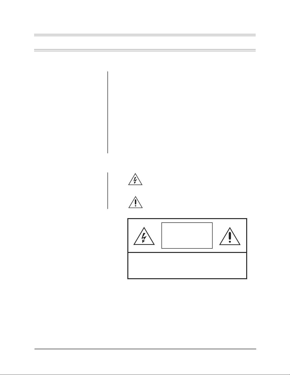
The product and/or manual may bear the following marks:
This symbol indicates that dangerous voltage constituting a
risk of electric shock is present within this unit.
This symbol indicates that there are important operating and
maintenance instructions in the literature accompanying this
unit.
CAUTION:
RISK OF
ELECTRIC SHOCK.
DO NOT OPEN.
TO REDUCE THE RISK OF ELECTRICAL SHOCK,
DO NOT REMOVE COVER. NO USER-
SERVICEABLE PARTS INSIDE. REFER SERVICING
TO QUALIFIED SERVICE PERSONNEL.
CAUTION:
Please thoroughly familiarize yourself with the information
in this manual prior to installation and operation.
Pelco Manual C1466M-A (5/98) 3
Page 4

1.2 UNPACKING INSTRUCTIONS
Unpack and inspect all parts carefully.
The following items are supplied:
1 Enclosure
1 Installation/Operation Manual (C1466M-A)
1 Parts bag (Parts may be used to attach the camera to the mount.)
1 Hex bolt, 1/4-20 x 1/2"
1 Split washer
1 Flat washer
Be sure to save the shipping carton, boxes and inserts. They are the safest material
in which to make future shipments.
If an item appears to have been damaged in shipment, replace it properly in its box
and contact the factory at 1-800-289-9100 or 1-559-292-1981 for a replacement.
(International customers fax 1-559-348-1120 for authorization and instructions.)
If an item needs to be returned to the factory for repair, consult the WARRANTY
AND RETURN section of this manual for instructions.
1.3 RECOMMENDED TOOLS
Pelco does not supply the basic tools needed for the installation process. The following tools are recommended.
To install the enclosure and camera:
Pin-in-hex wrench (Included to remove tamper-resistant screw.)
Small adjustable wrench
Phillips screwdriver
BNC crimp tool
Wire stripper
Wire cutter
Coaxial cable stripper
4 Pelco Manual C1466M-A (5/98)
Page 5

The information within this manual covers the installation of the HS8080/HS8134
low-profile high security enclosures.
The HS8080/HS8134 are high security ceiling mount enclosures designed for installations such as prisons, detention cells, etc., requiring maximum protection from
vandalism. The HS8080 is constructed from heavy gauge aluminum for moderate
damage resistance. The HS8134 is constructed from heavy gauge steel for high
damage resistance.
There is no exposed mounting hardware securing the HS8080/HS8134 to its mounting surface. Opening the enclosure can only be accomplished with a specially designed tool (included), eliminating the possibility of the enclosure being opened by
unauthorized persons. The HS8080/HS8134 features a removable, adjustable camera cradle for easy positioning. An impact-resistant Lexan® window is supplied with
the enclosure.
2.1 MODELS
2.0 DESCRIPTION
HS8080 High security ceiling mount enclosure constructed from heavy gauge
HS8134 High security ceiling mount enclosure constructed from heavy gauge
aluminum, designed for installations such as prisons, detention cells,
etc., requiring maximum protection from vandalism. Moderate damage
resistance.
steel, designed for installations such as prisons, detention cells, etc.,
requiring maximum protection from vandalism. High damage resistance.
Pelco Manual C1466M-A (5/98) 5
Page 6

3.0 INSTALLATION
3.1 ENCLOSURE INSTALLATION
To mount the HS8080/HS8134 enclosure, perform the following steps:
1. Determine the location and direction of the enclosure to be mounted.
2. Unlock the cover by unscrewing the tamper-resistant screw. (Pin-in-hex wrench
included to remove tamper-resistant screw.) Open the cover of the enclosure.
3. Remove the camera cradle by loosening the two 7/16-inch adjustment nuts
that hold the camera cradle to the enclosure.
4. Remove any appropriate knockout. Attach the enclosure to the ceiling using
the four mounting holes in the back of the enclosure.
Proceed to Section 3.2, CAMERA AND LENS INSTALLATION.
3.2 CAMERA AND LENS INSTALLATION
To mount the camera/lens directly into the enclosure, perform the following steps:
1. If you haven’t removed the camera cradle when you installed the enclosure,
remove it now. Loosen the two 7/16-inch adjustment nuts that hold the camera
cradle to the enclosure and remove the camera cradle.
2. Mount the camera/lens onto the camera cradle.
3. Route the appropriate cables into the enclosure. Make all necessary electrical
connections to the camera. Refer to Table A for the type of video coaxial cable
to use. If the camera will use 24 VAC power, refer to Table B to determine the
size of wire needed.
4. Reinstall the camera cradle, with camera/lens installed, into the enclosure.
Adjust the forward and backward position of the camera/lens to clear the enclosure cover when closed and tighten the two 7/16-inch adjustment nuts. Test
close the enclosure to see that the enclosure closes properly.
5. Loosen the two 10-32 phillips head tilt adjustment screws. Adjust the tilt adjustment screw nearest the enclosure hinge to tilt the camera down and the
screw closest the front of the enclosure to tilt the camera up. Test close the
enclosure to see that the enclosure closes properly.
Proceed to Section 3.3, TAMPER SWITCH CONNECTION (HS8080 ONLY), or
close and lock the cover with the tamper-resistant screw.
3.3 TAMPER SWITCH CONNECTION (HS8080 ONLY)
1. Wire the tamper switch. For a normally open circuit, use the “NO” and “common” terminals; for a normally closed circuit, use the “NC” and “common” terminals. Remember that the switch will be pushed down when you close the
cover.
2. Close and lock the cover with the tamper-resistant screw.
6 Pelco Manual C1466M-A (5/98)
Page 7

Table A. Video Coaxial Cable Wiring Distances
Cable Type* Maximum Distance
RG59 750 ft (229 m)
RG6 1,000 ft (305 m)
RG11 1,500 ft (457m )
* Minimum cable requirements:
75 ohms
All-copper center conductor
All-copper braided shield with 95-percent braid coverage
Table B. 24 VAC Wiring Distances
The following are the recommended maximum distances for 24 VAC applications
and are calculated with a 10-percent voltage drop. (Ten percent is generally the
maximum allowable voltage drop for AC-powered devices.)
EXAMPLE:
An enclosure that requires 80 vA and is installed 35 feet
(10 m) from the transformer would
require a minimum wire gauge of 20
Awg.
NOTE:
Distances are calculated in
feet; values in parentheses are
meters.
Wire Gauge
20 18 16 14 12 10
10 283 451 716 1142 1811 2880
(86) (137) (218) (348) (551) (877)
20 141 225 358 571 905 1440
(42) (68) (109) (174) (275) (438)
30 94 150 238 380 603 960
(28) (45) (72) (115) (183) (292)
40 70 112 179 285 452 720
(21) (34) (54) (86) (137) (219)
50 56 90 143 228 362 576
(17) (27) (43) (69) (110) (175)
60 47 75 119 190 301 480
(14) (22) (36) (57) (91) (146)
70 40 64 102 163 258 411
(12) (19) (31) (49) (78) (125)
80 35 56 89 142 226 360
(10) (17) (27) (43) (68) (109)
90 31 50 79 126 201 320
(9) (15) (24) (38) (61) (97)
100 28 45 71 114 181 288
(8) (13) (21) (34) (55) (87)
110 25 41 65 103 164 261
(7) (12) (19) (31) (49) (79)
120 23 37 59 95 150 240
Total vA consumed
(7) (11) (17) (28) (45) (73)
130 21 34 55 87 139 221
(6) (10) (16) (26) (42) (67)
140 20 32 51 81 129 205
(6) (9) (15) (24) (39) (62)
150 18 30 47 76 120 192
(5) (9) (14) (23) (36) (58)
160 17 28 44 71 113 180
(5) (8) (13) (21) (34) (54)
170 16 26 42 67 106 169
(4) (7) (12) (20) (32) (51)
180 15 25 39 63 100 160
(4) (7) (11) (19) (30) (48)
190 14 23 37 60 95 151
(4) (7) (11) (18) (28) (46)
200 14 22 35 57 90 144
(4) (6) (10) (17) (27) (43)
Maximum distance from transformer to load
Pelco Manual C1466M-A (5/98) 7
Page 8

4.0 MAINTENANCE
Regularly scheduled maintenance will prolong the operational life and appearance
of the enclosure. Clean the outer surface of the enclosure and the inner surface of
the viewing window with a nonabrasive cleaning cloth and antistatic cleaner that is
safe for use on acrylic plastic. Do not use kerosene or similar substances that may
damage the surface.
8 Pelco Manual C1466M-A (5/98)
Page 9

GENERAL
5.0 SPECIFICATIONS
Environment: Indoor (Usable outdoors under cover; that is, such as parking
garages)
Operating Range: 32° to 120°F (0° to 49°C)
Weight
Unit Shipping
HS8080: 2.65 lb (1.20 kg) 3 lb (1.35 kg)
HS8134: 4.15 lb (1.88 kg) 5 lb (2.27 kg)
Dimensions: See Figure 1
Rating: NEMA 1
MECHANICAL
Construction
HS8080: 0.078-inch (0.20 cm) aluminum
0.25-inch (0.63 cm) Lexan® viewing window
HS8134: 0.134-inch (0.34 cm) steel
0.50-inch (1.27 cm) Lexan® viewing window
Finish: Gray polyester powder coat
Enclosure
Mounting: Four 0.25-inch (0.63 cm) holes on rear surface
5.00 (12.70)
6.63
(16.84)
4.75
(12.07)
3.25 (8.25)
NOTE: VALUES IN PARENTHESES ARE CENTIMETERS; ALL OTHERS ARE INCHES.
13.00 (33.02)
5.00
(12.70)
Figure 1. HS8080/HS8134 Dimension Drawing
Pelco Manual C1466M-A (5/98) 9
Page 10

Max. Camera/
Lens Size: 3.5" H x 9.75" L x 3.0" W (8.89 x 24.77 x 7.62 cm)*
Camera Mounting: Removable, adjustable camera cradle
* Dimensions include BNC connector
Length may vary if width and height of camera and lens are
different.
Lock: Tamper-resistant 8-32 screw
Tamper Switch: Plunger-type door switch with “pull-to-cheat” feature. N.O./N.C.
ELECTRICAL
Cable Entry: One cable knockout hole on flat mounting surface.
Tamper Switch: 1/4" (.63 cm) quick disconnect. N.O./N.C. clearly marked on
(Pin-in-hex wrench included to remove tamper-resistant screw.)
contacts clearly marked on body of switch.
Two cable knockout holes on side of enclosure.
switch body. 10 A maximum switching current. 125 V maximum
switching voltage.
(Design and specifications are subject to change without notice.)
10 Pelco Manual C1466M-A (5/98)
Page 11

NOTES
Pelco Manual C1466M-A (5/98) 11
Page 12

6.0 WARRANTY AND RETURN INFORMATION
WARRANTY
Pelco will repair or replace, without charge, any merchandise proved defective in material or
workmanship for a period of one year after the date of shipment.
Exceptions to this warranty are as noted below:
Pelco, the Pelco logo, Camclosure, Esprit,
Genex, Legacy, and Spectra are registered
trademarks of Pelco.
Endura and ExSite are trademarks of Pelco.
© Copyright 1998, Pelco. All rights reserved.
• Five years on FT/FR8000 Series fiber optic products.
• Three years on Genex
• Three years on Camclosure
CC3751H-2, CC3651H-2X, MC3651H-2, and MC3651H-2X camera models, which have a fiveyear warranty.
• Two years on standard motorized or fixed focal length lenses.
• Two years on Legacy
dome products.
• Two years on Spectra
continuous motion applications.
• Two years on Esprit
• Eighteen months on DX Series digital video recorders, NVR300 Series network video
recorders, and Endura
• One year (except video heads) on video cassette recorders (VCRs). Video heads will be
covered for a period of six months.
• Six months on all pan and tilts, scanners or preset lenses used in continuous motion applications
(that is, preset scan, tour and auto scan modes).
Pelco will warrant all replacement parts and repairs for 90 days from the date of Pelco shipment.
All goods requiring warranty repair shall be sent freight prepaid to Pelco, Clovis, California. Repairs
made necessary by reason of misuse, alteration, normal wear, or accident are not covered under
this warranty.
Pelco assumes no risk and shall be subject to no liability for damages or loss resulting from the
specific use or application made of the Products. Pelco’s liability for any claim, whether based on
breach of contract, negligence, infringement of any rights of any party or product liability, relating
to the Products shall not exceed the price paid by the Dealer to Pelco for such Products. In no event
will Pelco be liable for any special, incidental or consequential damages (including loss of use, loss
of profit and claims of third parties) however caused, whether by the negligence of Pelco or
otherwise.
The above warranty provides the Dealer with specific legal rights. The Dealer may also have
additional rights, which are subject to variation from state to state.
If a warranty repair is required, the Dealer must contact Pelco at (800) 289-9100 or (559) 292-1981
to obtain a Repair Authorization number (RA), and provide the following information:
1. Model and serial number
2. Date of shipment, P.O. number, Sales Order number, or Pelco invoice number
3. Details of the defect or problem
If there is a dispute regarding the warranty of a product which does not fall under the warranty
conditions stated above, please include a written explanation with the product when returned.
Method of return shipment shall be the same or equal to the method by which the item was received
by Pelco.
RETURNS
In order to expedite parts returned to the factory for repair or credit, please call the factory at (800)
289-9100 or (559) 292-1981 to obtain an authorization number (CA number if returned for credit,
and RA number if returned for repair).
All merchandise returned for credit may be subject to a 20% restocking and refurbishing charge.
Goods returned for repair or credit should be clearly identified with the assigned CA or RA number
and freight should be prepaid. Ship to the appropriate address below.
If you are located within the continental U.S., Alaska, Hawaii or Puerto Rico, send goods to:
If you are located outside the continental U.S., Alaska, Hawaii or Puerto Rico and are instructed
to return goods to the USA, you may do one of the following:
If the goods are to be sent by a COURIER SERVICE, send the goods to:
Service Department
Pelco
3500 Pelco Way
Clovis, CA 93612-5699
Pelco
3500 Pelco Way
Clovis, CA 93612-5699 USA
If the goods are to be sent by a FREIGHT FORWARDER, send the goods to:
Pelco c/o Expeditors
473 Eccles Avenue
South San Francisco, CA 94080 USA
Phone: 650-737-1700
Fax: 650-737-0933
®
Series products (multiplexers, server, and keyboard).
®
and fixed camera models, except the CC3701H-2, CC3701H-2X,
®
, CM6700/CM6800/CM9700 Series matrix, and DF5/DF8 Series fixed
®
, Esprit®, ExSite™, and PS20 scanners, including when used in
®
and WW5700 Series window wiper (excluding wiper blades).
™
Series distributed network-based video products.
12 Pelco Manual C1466M-A (5/98)
 Loading...