

Page 1
®
HS8000/HS8013 High-Security
Camera Enclosures
Installation/Operation Manual
C480M-F (10/04)
Pelco • 3500 Pelco Way, Clovis, CA 93612-5699 • USA • www.pelco.com
In North America and Canada: Tel (800) 289-9100 • FAX (800) 289-9150
International Customers: Tel (1-559) 292-1981 or FAX (1-559) 348-1120
Page 2

CONTENTS
Section Page
1.0 GENERAL..................................................................................................1
1.1 IMPORTANT SAFEGUARDS AND WARNINGS ...............................1
2.0 DESCRIPTION ..........................................................................................2
2.1 OPTIONS...........................................................................................2
3.0 INSTALLATION ..........................................................................................3
3.1 WINDOW SELECTION......................................................................3
3.2 WALL/CEILING MOUNTING .............................................................5
3.3 CM8000 CORNER MOUNT INSTALLATION ....................................5
3.4 HS8000CA CEILING ADAPTER PLATE INSTALLATION..................6
3.5 OPTIONAL HK8000/HK8024 HEATER KITS ....................................7
3.6 ELECTRICAL CONNECTION............................................................7
3.7 CAMERA/LENS INSTALLATION ....................................................... 8
3.8 TAMPER SWITCH INSTALLATION...................................................8
4.0 CARE AND MAINTENANCE .....................................................................9
5.0 EXPLODED ASSEMBLY DRAWING ........................................................10
6.0 SPECIFICATIONS ....................................................................................11
7.0 WARRANTY AND RETURN INFORMATION ...........................................14
LIST OF ILLUSTRATIONS
Figure Page
1 HS8000/HS8013 Mounting Template.................................................4
2 CM8000 Corner Mount Installation .................................................... 5
3 HS8000CA Ceiling Adapter Plate Installation ....................................6
4 HK8000/HK8024 Heater Kit Installation.............................................7
5 HK8000/HK8024 Heater Kit Wiring Diagram .....................................7
6 HS8000 Exploded Assembly Drawing ..............................................10
7 HS8000 Dimension Drawing.............................................................12
8 HS8000CA Ceiling Adapter Plate Dimension Drawing .....................12
LIST OF TABLES
Table Page
A Mechanical Parts List ........................................................................10
REVISION HISTORY
Manual # Date Comments
C480M 7/89 Original manual for AH8000.
C480M 9/89 Rev. A. Revised manual style. Minor changes made to
C480M 10/89 Rev. B. Manual revised to reflect model number change
C480M 1/91 Rev. C. Updated manual style, added isometric drawings.
C480M-D 9/95 Rev. D. Manual revised to include tamper switch option
C480M-E 2/96 Rev. E. Revised to include updated specification
C480M-F 6/97 Rev. F. Revised to include new model HS8013.
C480M-E 10/04 Removed agency logos and Section 2.2, Certifications.
16 Pelco Manual C480M-F (10/04)
ii
installation information and mechanical Parts List.
to HS8000.
Ceiling adaptor plate installation diagram and dimension
drawing added to manual.
installation/operation information. Updated manual to
new style. Revised mounting template.
description, installation instructions, and part numbers
for tamper switch update per ECO 95-357.
Updated warranty and return information.
Page 3
1.0 GENERAL
1.1 IMPORTANT SAFEGUARDS AND WARNINGS
Prior to installation and use of this product, the following WARNINGS should be
observed.
1. Installation and servicing should only be done by Qualified Service Personnel
and conform to all Local codes.
2. Unless the unit is specifically marked as a NEMA Type 3, 3R, 3S, 4, 4X, 6, or
6P enclosure, it is designed for indoor use only and it must not be installed
where exposed to rain and moisture.
3. Only use replacement parts recommended by Pelco.
4. The camera and lens combination shall not exceed 20 lbs (9 kg).
5. The installation method and materials should be capable of supporting four
(4) times the weight of the enclosure, pan/tilt, camera and lens combination.
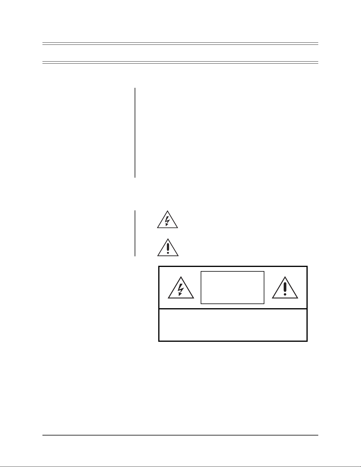
The product and or product manual may bear the following
marks:
This symbol indicates that dangerous voltage constituting a
risk of electric shock is present within this unit.
This symbol indicates that there are important operating and
maintenance instructions in the literature accompanying this
unit.
CAUTION:
RISK OF
ELECTRIC SHOCK.
DO NOT OPEN.
TO REDUCE THE RISK OF ELECTRICAL SHOCK,
DO NOT REMOVE COVER. NO USER-
SERVICEABLE PARTS INSIDE. REFER SERVICING
TO QUALIFIED SERVICE PERSONNEL.
CAUTION:
Please thoroughly familiarize yourself with the information
in this manual prior to installation and operation.
Pelco Manual C480M-F (10/04) 1
Page 4

2.0 DESCRIPTION
The HS8000/HS8013 is a high security camera enclosure designed for installations such as prisons, detention cells, etc., requiring maximum protection from vandalism.
Constructed from heavy gauge steel, the HS8000 will accept most CCD cameras
with fixed focal length lenses ranging in size from 4 mm to 75 mm. Larger lens size
combinations can be considered when using the HS8013. There is no exposed mounting hardware securing the HS8000/HS8013 to its mounting surface. Opening the
enclosure can only be accomplished with a specially designed tool, eliminating the
possibility of the enclosure being opened by unauthorized persons. Designed to function either as a wall enclosure or a ceiling enclosure, the HS8000/HS8013 features
three possible window positions. An impact resistant, .50" (1.27 cm) thick, Lexan
window is supplied with the enclosure.
2.1 OPTIONS
CM8000 Corner mount for HS8000/HS8013.
HK8000 Thermostatically controlled heater kit, 120 VAC. Provides 80
HK8024 Thermostatically controlled heater kit, 24 VAC. Provides 80
HS8000CA Ceiling adapter plate for use with HS8000 only . Gives the HS8000
watts of heat.
watts of heat.
the appearance of being mounted flush with the ceiling.
2 Pelco Manual C480M-F (10/04)
Page 5

3.0 INSTALLATION
NOTE:
Unless otherwise noted all
instructions, drawing, etc. apply to
both the HS8000 and HS8013 except
for the ceiling adapter. The
HS8000CA ceiling adapter will not
work with the HS8013.
NOTE:
The four (4) fasteners required to secure the enclosure to the
mounting surface (minimum 3/8" diameter recommended) are not supplied.
NOTE:
A speaker grill for a 4" (10.16
cm) speaker is provided with a blockoff plate. When using the speaker
grill, make certain that the speaker
you provide does not interfere with the
camera.
Before installing the enclosure to a wall or ceiling, make certain that the mounting
surface is able to support the full load of the enclosure plus all other equipment
such as camera, lens, etc.
The tilt table bracket may be removed to provide adequate clearance for mounting
the enclosure.
3.1 WINDOW SELECTION
After the enclosure position (wall or ceiling) has been selected, the appropriate
viewing port must be selected. The enclosure is shipped standard for wall installations with the window in the uppermost position. If using any other than the standard port, follow the steps outlined below to position the viewing window. If using
the standard port, refer to Section 4.2 for mounting instructions.
1. Remove the two (2) tamper-resistant screws and open the cover. A special
socket is provided (fits 1/4" square drive).
2. The window, speak er plate , and filler plate are held in place with twelv e (12)
1/4-20 nuts. Remove the nuts and lock washers.
3. Remove the window, speaker plate, and blank plate as needed.
4. Place the window in the desired viewing port and the filler plates (or speaker
grill and filler plate) in the unused openings.
5. Secure with the 1/4-20 nuts and lock washers. Tighten all hardware.
6. Close the lid. And reinstall the 1/4-20 Tampruf fasteners.
Pelco Manual C480M-F (10/04) 3
Page 6

3/8" Mounting Hole, 4X
HS8000/HS8013
Mounting Template
1" Cable Entry Hole, 2X
.75"
Figure 1. HS8000/HS8013 Mounting Template
3.25"
2.0"
Page 7

3.2 WALL/CEILING MOUNTING
To mount the enclosure to a wall or ceiling, follow the steps outlined below.
1. Remove the two (2) tamper-resistant screws and open the cover. A special
socket is provided (fits 1/4" square drive).
2. Using the enclosure or the template provided (see Figure 3), mark and drill
holes in the mounting surface.
3. Knock out any of the two (2) cable entry holes desired on the enclosure body.
4. Attach the enclosure with the required fasteners.
5. Route all cables through the appropriate knockouts.
3.3 CM8000 CORNER MOUNT INSTALLATION
NOTE:
The four (4) fasteners (minimum 3/8" diameter recommended)
required to secure the CM8000 to a
wall, and the four (4) 5/16-18 fasteners required to secure the enclosure
to the CM8000, are not supplied.
Before installing the CM8000 corner mount to a wall, make certain that the mounting surface is able to support the full load of the enclosure, mount, and all other
equipment such as camera, lens, etc.
To install the CM8000 and mount the enclosure, perform the following steps (see
Figure 2):
1. Position the CM8000 in the desired corner and use as a template for marking
the four (4) mounting holes. Mark the holes and drill.
2. Mount the CM8000 with the required fasteners (not supplied). Route the cables
into the mount.
3. Open the cover.
4. Knock out any of the two (2) cable entry holes desired on the enclosure body.
5. Route all cables through the appropriate knockouts.
6. Attach the enclosure to the CM8000 with the required fasteners.
Refer to Section 3.6, Electrical Connection, and Section 3.7, Camera/Lens Installation for further details.
Figure 2. CM8000 Corner Mount Installation
Pelco Manual C480M-F (10/04) 5
Page 8

3.4 HS8000CA CEILING ADAPTER PLATE INSTALLATION
(For HS8000 only)
Before installing the HS8000CA ceiling adapter plate, make sure the mounting surface is able to support the full load of the enclosure, mount, and all other equipment
such as the camera, lens, etc.
NOTE:
The HS8000CA ceiling
adapter plate is provided with six (6)
10-32 screws, nuts and nylon washers. Before continuing with the installation of the adapter plate, make sure
these six screws, nuts and washers
are included. If not, please contact the
factory to obtain them.
NOTE:
The HS8000CA Ceiling
Adapter is not compatible withe the
HS8013 enclosure
To install the HS8000CA ceiling adapter plate, perform the following:
1. Place the HS8000CA ceiling adapter plate on the HS8000 enclosure as shown
in Figure 3.
2. Next, drill six (6) 0.187" (3/16") holes in the enclosure at the location of each of
the mounting holes on the HS8000CA ceiling adapter plate.
3. Place a nylon washer on the 10-32 screw and insert it through the HS8000CA
ceiling adapter plate mounting hole and the hole in the enclosure drilled in
step 2. Then install a nut on the 10-32 screw and tighten. Repeat this step for
each of the six (6) mounting holes.
4. Mount the enclosure as described in Section 4.2 of this manual.
Figure 3. HS8000CA Ceiling Adapter Plate Installation
6 Pelco Manual C480M-F (10/04)
Page 9

3.5 OPTIONAL HK8000/HK8024 HEATER KITS
The HK8000 and HK8024 Heater Kits require 120 V A C or 24 VAC respectively , and
both provide 80 watts of heat which is thermostatically controlled to activate at 40°
F and turn off at 60° F
3.5.1 Recommended Cable Size
The following cable sizes are the minimum recommended for use with heater kits.
120 VAC Operation 24 VAC Operation
22 Awg to 400 ft (121.9 m) 20 Awg to 35 ft (10.7 m)
20 Awg to 650 ft (198.12 m) 18 Awg to 60 ft (18.3 m)
18 Awg to 1,100 ft (335.3 m) 16 Awg to 80 ft (24.4 m)
3.5.2 Heater Kit Installation
To install the HK8000/HK8024, perform the following steps (refer to Figure 4):
1. Open the cover.
2. Attach the heater pads to each side of the tilt table bracket.
3. Press the PC board assembly into the four (4) holes provided in the tilt table
bracket.
4. Wire according to the diagram shown in Figure 5.
5. Close and lock the cover.
CAUTION:
When a single power
source is used for both the camera
and accessories, the camera power
consumption must be taken into consideration when determining the wire
gauge. Also, make certain that all
electrical connections are done properly and meet electrical codes.
3.6 ELECTRICAL CONNECTION
After the cable has been routed, all wire connections should be made (i.e., video,
lens, camera power, heaters). A 6-position terminal block has been provided to
assist in this.
1
2
3
4
5
6
7
8
9
10
WHT
WHT
WHT
WHT
AC HI INPUT
AC NT INPUT
GROUND
HEATER
40 WATTS
HEATER
40 WATTS
Figure 4. HK8000/HK8024 Heater Kit Installation Figure 5. HK8000/HK8024 Heater Kit Wiring Diagram
Pelco Manual C480M-F (10/04) 7
Page 10

3.7 CAMERA/LENS INSTALLATION
NOTE:
The tilt table bracket and tilt
table may be removed from the enclosure to aid in camera/lens installation.
Now that the proper window viewing location has been determined and the enclosure has been mounted, you are ready to mount your camera lens to the enclosure.
Refer to the following steps.
1. Loosen the tilt table mounting bolts.
2. Securely attach the camera/lens to the desired location on the tilt table.
3. Make all necessary electrical connections (video, camera power, etc.).
4.. Position the tilt table at the desired location and angle, and tighten the hardware.
5. Close the lid to ensure that there is no interference.
6. Provide power to the camera and check for adequate video image.
3.8 TAMPER SWITCH INSTALLATION
The HS8000 enclosures come standard from the factory with a tamper switch installed. Should it become necessary to install a replacement switch, refer to Figure
6 for the correct position of the bracket/switch and perform the following steps:
1. Remove the front cover.
2. Install the bracket/switch and secure with lockwashers and nuts.
3.8.1 Wiring the Switch
The tamper switch comes with both a “Normally Open” contact and a “Normally
Closed” contact.
For a “Normally Open” circuit, use the “open” and “common” terminals; for a “Normally Closed” circuit, use the “closed” and “common” terminals.
8 Pelco Manual C480M-F (10/04)
Page 11

4.0 CARE AND MAINTENANCE
Regularly scheduled maintenance will help prolong the operational life and appearance of the equipment.
Clean the viewing window regularly with a soft cloth, using a mild, nonabrasive
detergent and water solution to help maintain picture clarity.
Pelco Manual C480M-F (10/04) 9
Page 12

5.0 EXPLODED ASSEMBLY DRAWING
Figure 6. HS8000 Exploded Assembly Drawing
Table A. Mechanical Parts List
Item Quantity Description Part Number
11Window, Lexan, 5.75" x 4" x .5", MR5 AH800010001
21Body (HS8000) AH80001000WA
31Hinge, steel HS80004008COMP
41Cover, body AH80004012COMP
51Bracket, tilt table mount (HS8000) AH80004014COMP
61Tilt table AH80004013COMP
71Plate, blank window AH80004015COMP
82Screw, 1/4-20 x 1/2", Tampruf #10 ZH1/4-20X.50SRT
91Socket, Tampruf #10 (not shown) ZTSOCKET10
10 1 Speaker plate AH80004115COMP
11 5 NP gasket 1/8" x 1/4" x foot (not shown) EH110042
12 1 Plate, grill, block-off HS80004115COMP
13 1 Terminal block 6-position 601-6 Kulka (not shown) TRB6-141
14 1 Switch, Tamper SWI1DM401
15 1 Switch Bracket, Tamper HS30004113COMP
1 Body (HS8013) HS80131000WA
1 Bracket, tilt table mount (HS8013) HS80134000COMP
10 Pelco Manual C480M-F (10/04)
Page 13

6.0 SPECIFICATIONS
MECHANICAL
Window: 1/2" (1.27 cm) thick; impact and abrasion resistant Lexan
Camera Mounting: Adjustable tilt table
Camera and Lens Size: Accepts camera and lens combinations (including BNC
HS8000 4.0" H x 4.0" W x 8.0" L
HS8013 4.0" H x 4.0" W x 11.0" L
Enclosure Mounting: Four (4) .390" (0.99 cm) diameter holes on protected rear
Security: Tamper-resistant screws N.O./N.C. switch contact on
Tamper Switch: Plunger type door switch with “pull to cheat” feature. N.O./
ELECTRICAL
Cable Entry: Six position terminal block. Two (2) cable knockouts holes
Tamper Switch: 1/4" (.63 cm) quick connect. N.O./N.C. clearly marked
GENERAL
Construction: Seam welded 10 gauge .134" (0.34 cm) steel
Finish: Polyester powder coat
connector) up to:
(10.16 cm x 10.16 cm x 20.32 cm)
(10.16 cm x 10.16 cm x 27.94 cm)
surface
cover
N.C. contacts clearly marked on body of switch. DM electrical rating: 10A, 125V. Plunger type with .20" (0.51 cm)
on flat mounting surface
on switch body. 10A, maximum switching current 125V,
maximum switching voltage.
Dimensions: See Figures 7 and 8
Design and specifications are subject to change without notice.
Pelco Manual C480M-F (10/04) 11
Page 14

Figure 7. HS8000/HS8013 Dimension Drawing
Figure 8. HS8000CA Ceiling Adapter Plate Dimension Drawing
12 Pelco Manual C480M-F (10/04)
Page 15

NOTES
Pelco Manual C480M-F (10/04) 13
Page 16

7.0 WARRANTY AND RETURN INFORMATION
WARRANTY
Pelco will repair or replace, without charge, an y merchandise prov ed defectiv e in material or
workmanship for a period of one year after the date of shipment.
Exceptions to this warranty are as noted below:
• Five years on FT/FR8000 Series fiber optic products and the following fixed camera
models: CC3701H-2, CC3701H-2X, CC3751H-2, CC3651H-2X, MC3651H-2, and
CC3651H-2X.
Pelco, the Pelco logo, Spectra, Genex,
Legacy, Esprit, and Camclosure are
registered trademarks of Pelco.
©Copyright 2004, Pelco. All rights
reserved.
• Three years on all other fixed camera models (including Camclosure
Camera Systems) and Genex
• Two years on all standard motorized or fixed focal length lenses.
• Two years on Legacy®, CM6700/CM6800/CM8500/CM9500/CM9700 Series Matrix,
DF5 and DF8 Series Fixed Dome products.
• Two years on Spectra®, Esprit®, and PS20 Scanners, including when used in
continuous motion applications.
• Two years on Esprit
• Eighteen months on DX Series digital video recorders and NVR300 Series network
video recorders.
• One year (except video heads) on video cassette recorders (VCRs). Video heads will
be covered for a period of six months.
• Six months on all pan and tilts, scanners or preset lenses used in continuous motion
applications (that is, preset scan, tour and auto scan modes).
Pelco will warrant all replacement parts and repairs for 90 da ys from the date of Pelco shipment.
All goods requiring warranty repair shall be sent freight prepaid to Pelco, Clovis, California.
Repairs made necessary by reason of misuse, alteration, normal wear, or accident are not
covered under this warranty.
Pelco assumes no risk and shall be subject to no liability for damages or loss resulting from
the specific use or application made of the Products. Pelco’s liability for any claim, whether
based on breach of contract, negligence, infringement of any rights of any party or product
liability, relating to the Products shall not exceed the price paid by the Dealer to Pelco for
such Products. In no event will Pelco be liable for any special, incidental or consequential
damages (including loss of use, loss of profit and claims of third parties) however caused,
whether by the negligence of Pelco or otherwise.
The above warranty provides the Dealer with specific legal rights. The Dealer ma y also hav e
additional rights, which are subject to variation from state to state.
If a warranty repair is required, the Dealer must contact Pelco at (800)289-9100 or (559)
292-1981 to obtain a Repair Authorization number (RA), and provide the following inf ormation:
1. Model and serial number
2. Date of shipment, P.O. number, Sales Order number, or Pelco invoice number
3. Details of the defect or problem
If there is a dispute regarding the warranty of a product which does not fall under the warranty
conditions stated above, please include a written explanation with the product when returned.
Method of return shipment shall be the same or equal to the method by which the item was
received by Pelco.
RETURNS
In order to expedite parts returned to the factory for repair or credit, please call the factory at
(800) 289-9100 or (559) 292-1981 to obtain an authorization number (CA number if returned
for credit, and RA number if returned for repair).
All merchandise returned for credit may be subject to a 20% restocking and refurbishing
charge.
Goods returned for repair or credit should be clearly identified with the assigned CA or RA
number and freight should be prepaid. Ship to the appropriate address below.
If you are located within the continental U.S., Alaska, Ha waii or Puerto Rico, send goods to:
If you are located outside the continental U.S., Alaska, Ha waii or Puerto Rico and are instructed
to return goods to the USA, you may do one of the following:
If the goods are to be sent by a COURIER SERVICE, send the goods to:
If the goods are to be sent by a FREIGHT FORWARDER, send the goods to:
Service Department
Pelco
3500 Pelco Way
Clovis, CA 93612-5699
Pelco
3500 Pelco Way
Clovis, CA 93612-5699 USA
Pelco c/o Expeditors
473 Eccles Avenue
South San Francisco, CA 94080 USA
Phone: 650-737-1700
Fax: 650-737-0933
®
®
Series (multiplexers, server, and keyboard).
and WW5700 Series window wiper (excluding wiper blades).
®
Integrated
14 Pelco Manual C480M-F (10/04)
 Loading...