

Page 1
INSTALLATION
HS2100
Ceiling Enclosure
C1465M-A (9/06)
Page 2
Important Safety Instructions
1. Installation and servicing should be done only by qualified service personnel and conform to all Local codes.
2. Unless the unit is specifically marked as a NEMA Type 3, 3R, 3S, 4, 4X, 6, or 6P enclosure, it is designed for indoor use only and it must not be installed where exposed to rain and moisture.
3. Only use replacement parts recommended by Pelco.
4. After replacement/repair of this unit’s electrical components, conduct a resistance measurement between line and exposed parts to verify the exposed parts have not been connected to line circuitry.
5. The installation method and materials should be capable of supporting four times the weight of the enclosure, pan/tilt, camera and lens combination.
The product and/or manual may bear the following marks:
This symbol indicates that dangerous voltage constituting a risk of
electric shock is present within this unit.
CAUTION:
This symbol indicates that there are important operating and
maintenance instructions in the literature accompanying this unit.
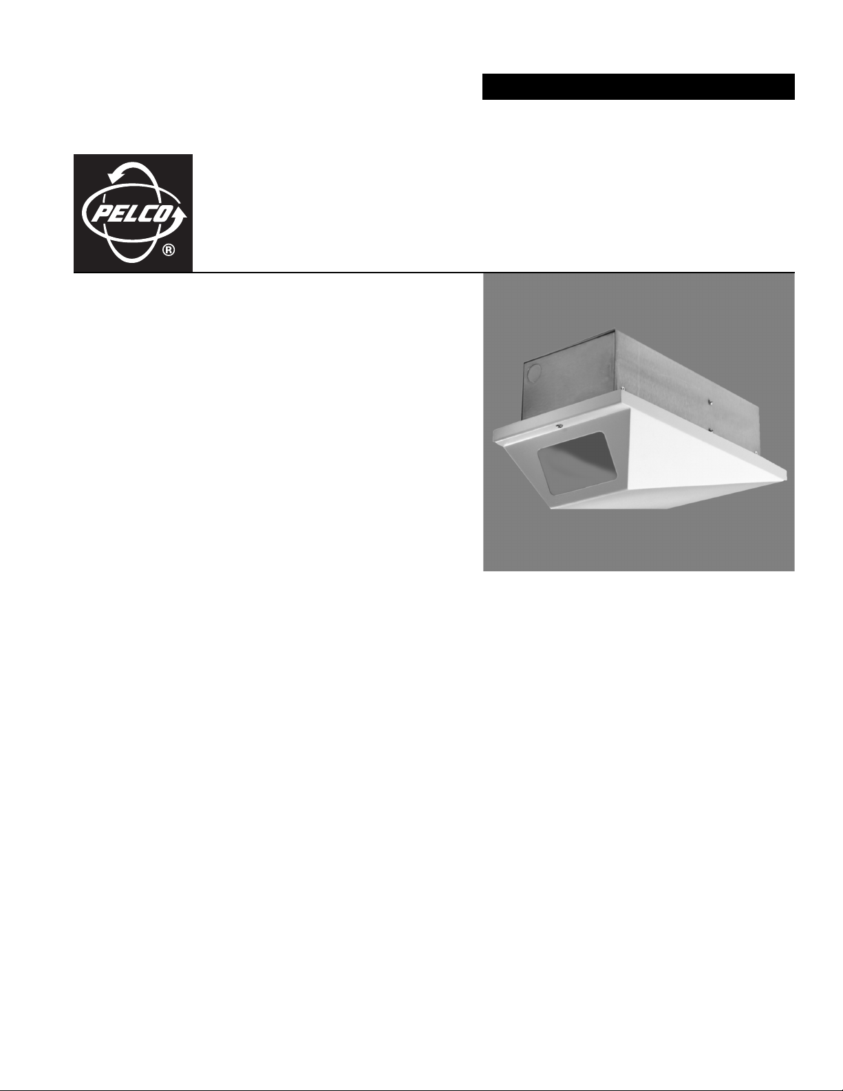
Description
The HS2100 is a low-profile, high-security ceiling enclosure with rivited back box for mounting in fixed or dropped ceilings. The unobtrusive,
compact design complements any business or office decor and provides maximum surveillance for fixed applications when using CCD cameras.
The HS2100 is engineered for ease of installation and service. The upper section, mounted above the ceiling, is constructed of aluminum.
Because of its lightweight design, the upper section can be mounted directly on a ceiling tile without the use of additional mounting plates.
The lower section is made of steel to provide extra security. It is hinged to provide convenient access for camera and lens adjustments. The
adjustable camera mounting sled allows the camera to be positioned vertically or horizontally, depending on the camera size.
OPTIONAL ACCESSORY
E2100 Rotating mounting plate with 360 degrees of rotation in 10-degree increments. Features locking capability to secure enclosure
positioning. Replaces 2-ft x 2-ft (60.96 cm x 60.96 cm) ceiling tile. Can be used in 2-ft x 4-ft (60.96 cm x 121.92 cm) ceiling tile
with additional “T” rail for support. Constructed of aluminum with textured white polyester powder coat finish.
RISK OF ELECTRIC SHOCK.
DO NOT OPEN.
2 C1465M-A (9/06)
Page 3

Installation
The following items are supplied:
1Enclosure
1 Parts bag (Parts may be used to attach the camera to the mount.)
1 Hex bolt, 1/4-20 x 1/2"
1 Split washer
1Flat washer
1 Backup flanges to support the enclosure if adequate mounting support is not available or if enclosure is mounted in drop ceiling tiles
1 Pin-in-hex wrench to remove tamper-resistant screw
Recommended Tools
Pelco does not supply the basic tools needed for the installation process. The following tools are recommended:
Small adjustable wrench
Phillips screwdriver
BNC crimp tool
Wire stripper
Wire cutter
Coaxial cable stripper
BACK BOX INSTALLATION
To mount the HS2100, perform the following steps:
NOTE: Backup flanges have been supplied to support the enclosure if adequate mounting support is not available or if you are mounting the
enclosure in drop ceiling tiles.
1. Determine the location and direction of the enclosure to be mounted. Ideally, the enclosure cutout should be parallel and adjacent, or perpendicular, to any ceiling structure. Avoid cutting into any ceiling structural members.
2. Unlock the enclosure cover by unscrewing the tamper-resistant screw (pin-in-hex wrench is included to remove tamper-resistant screw). Open the cover to expose the mounting holes in the flange.
3. Remove any appropriate knockouts.
4. Insert the enclosure into the opening and secure with the appropriate fasteners.
CAMERA AND LENS INSTALLATION
To mount the camera and lens, perform the following steps:
1. Mount the camera and lens onto the adjustable camera cradle. Adjust the position of the camera and lens to clear the enclosure cover when closed. Tighten the camera cradle fasteners.
2. Route the appropriate cables into the enclosure. Make all necessary electrical connections. Refer to Table A for the type of video coaxial cable to use. If the camera will use 24 VAC power, refer to Table B to determine the size of wire needed.
3. Close and lock the cover with the provided tamper-resistant screw.
C1465M-A (9/06) 3
Page 4

Table A. Video Coaxial Cable Wiring Distances
Cable Type* Maximum Distance
RG59/U 750 ft (229 m)
RG6/U 1,000 ft (305 m)
RG11/U 1,500 ft (457 m)
*Cable requirements:
75 ohms
All-copper center conductor
All-copper braided shield with 95-percent braid coverage
Table B. 24 VAC Wiring Distances
The following are the recommended maximum distances for 24 VAC applications and are calculated with a 10 percent voltage drop.
(Ten percent is generally the maximum allowable voltage drop for AC-powered devices.)
Wire Gauge
Tot a l VA
10
20
30
40
50
22
2
(0.4 mm
)20(0.5 mm2)18(1.0 mm2)16(1.5 mm2)14(2.5 mm2)12(4.0 mm2)10(6.0 mm2)
178
(54)
89
(27)
59
(17)
44
(13)
35
(10)
283
(86)
141
(42)
94
(28)
70
(21)
56
(17)
451
(137)
225
(68)
150
(45)
112
(34)
90
(27)
716
(218)
358
(109)
238
(72)
179
(54)
143
(43)
1142
(348)
571
(174)
380
(115)
285
(86)
228
(69)
1811
(551)
905
(275)
603
(183)
452
(137)
362
(110)
2880
(877)
1440
(438)
960
(292)
720
(219)
576
(175)
transformer to load
Maximum distance from
EXAMPLE: An enclosure that requires 30 VA and is installed 94 feet (28 m) from the transformer would require a minimum wire gauge of
20 AWG.
NOTE: Distances are calculated feet; values in parentheses are meters.
4 C1465M-A (9/06)
Page 5

Maintenance
Regularly scheduled maintenance will prolong the operational life and appearance of the enclosure. Clean the outer surface of the enclosure
with a nonabrasive cleaning cloth and antistatic cleaner. Clean the viewing window with a mild, nonabrasive soap and water to maintain picture
clarity. Do not use kerosene or similar substances that may damage the surface.
C1465M-A (9/06) 5
Page 6

Specifications
GENERAL
Environment Indoor only
Operating Range 32° to 120°F (0° to 49°C)
Weight 5.30 lb (2.41 kg)
MECHANICAL
Construction
Upper section 5052-H32 aluminum
Lower section 16 gauge steel
Viewing window 0.25" (6.35 mm) thick, abrasion-resistant Lexan
Finish White polyester powder coat
Cable Entry Two cable knockout holes
Dimensions See dimension drawing
Lock Tamper-resistant 8-32 screw
Ceiling Mounting Upper section flange-mounted to fixed ceiling or ceiling tile. Ceiling support rails are provided.
Maximum Camera/Lens Size 3" H x 4" W x 10" L (7.62 x 10.16 x 25.4 cm)*
Camera Mounting Adjustable camera sled capable of supporting a maximum weight of 10 lb (4.53 kg). Sled can be adjusted
(Design and product specifications are subject to change without notice.)
®
polycarbonate resin thermoplastic
(Pin-in-hex wrench included to remove tamper-resistant screw.)
*Dimensions include BNC connector
Length may vary if width and height of camera and lens are different.
horizontally or vertically.
5.75
(14.61)
7.00
(17.78)
3.50
(8.89)
7.50
(19.05)
NOTE: VALUES IN PARENTHESES ARE CENTIMETERS;
ALL OTHERS ARE INCHES.
11.75
(29.85)
MAX CAMERA LENGTH
10.00 (25.40)
13.50
(23.29)
6 C1465M-A (9/06)
Page 7

PRODUCT WARRANTY AND RETURN INFORMATION
WARRANTY
Pelco will repair or replace, without charge, any merchandise proved defective in material or
workmanship for a period of one year after the date of shipment.
Exceptions to this warranty are as noted below:
• Five years on FT/FR8000 Series fiber optic products.
• Three years on Genex
• Three years on Camclosure
CC3701H-2X, CC3751H-2, CC3651H-2X, MC3651H-2, and MC3651H-2X camera models,
which have a five-year warranty.
• Three years on PMCL 200/300/400 Series LCD monitors.
• Two years on standard motorized or fixed focal length lenses.
• Two years on Legacy
dome products.
• Two years on Spectra
continuous motion applications.
• Two years on Esprit
• Two years (except lamp and color wheel) on Digital Light Processing (DLP
The lamp and color wheel will be covered for a period of 90 days. The air filter is not
covered under warranty.
• Eighteen months on DX Series digital video recorders, NVR300 Series network video
recorders, Endura
twisted pair transmission products.
• One year (except video heads) on video cassette recorders (VCRs). Video heads will be
covered for a period of six months.
• Six months on all pan and tilts, scanners or preset lenses used in continuous motion
applications (that is, preset scan, tour and auto scan modes).
Pelco will warrant all replacement parts and repairs for 90 days from the date of Pelco
shipment. All goods requiring warranty repair shall be sent freight prepaid to Pelco, Clovis,
California. Repairs made necessary by reason of misuse, alteration, normal wear, or accident
are not covered under this warranty.
Pelco assumes no risk and shall be subject to no liability for damages or loss resulting from
the specific use or application made of the Products. Pelco’s liability for any claim, whether
based on breach of contract, negligence, infringement of any rights of any party or product liability, relating to the Products shall not exceed the price paid by the Dealer to Pelco for such
Products. In no event will Pelco be liable for any special, incidental or consequential damages
(including loss of use, loss of profit and claims of third parties) however caused, whether by
the negligence of Pelco or otherwise.
The above warranty provides the Dealer with specific legal rights. The Dealer may also have
additional rights, which are subject to variation from state to state.
®
Series products (multiplexers, server, and keyboard).
®
and fixed camera models, except the CC3701H-2,
®
, CM6700/CM6800/CM9700 Series matrix, and DF5/DF8 Series fixed
®
, Esprit®, ExSite™, and PS20 scanners, including when used in
®
and WW5700 Series window wiper (excluding wiper blades).
™
Series distributed network-based video products, and TW3000 Series
®
) displays.
If a warranty repair is required, the Dealer must contact Pelco at (800)þ289-9100 or
(559) 292-1981 to obtain a Repair Authorization number (RA), and provide the following
information:
1. Model and serial number
2. Date of shipment, P.O. number, Sales Order number, or Pelco invoice number
3. Details of the defect or problem
If there is a dispute regarding the warranty of a product which does not fall under the
warranty conditions stated above, please include a written explanation with the product when
returned.
Method of return shipment shall be the same or equal to the method by which the item was
received by Pelco.
RETURNS
In order to expedite parts returned to the factory for repair or credit, please call the factory at
(800) 289-9100 or (559) 292-1981 to obtain an authorization number (CA number if returned for
credit, and RA number if returned for repair).
All merchandise returned for credit may be subject to a 20% restocking and refurbishing
charge.
Goods returned for repair or credit should be clearly identified with the assigned CA or RA
number and freight should be prepaid. Ship to the appropriate address below.
If you are located within the continental U.S., Alaska, Hawaii or Puerto Rico, send goods to:
Service Department
Pelco
3500 Pelco Way
Clovis, CA 93612-5699
If you are located outside the continental U.S., Alaska, Hawaii or Puerto Rico and are
instructed to return goods to the USA, you may do one of the following:
If the goods are to be sent by a COURIER SERVICE, send the goods to:
Pelco
3500 Pelco Way
Clovis, CA 93612-5699 USA
If the goods are to be sent by a FREIGHT FORWARDER, send the goods to:
Pelco c/o Expeditors
473 Eccles Avenue
South San Francisco, CA 94080 USA
Phone: 650-737-1700
Fax: 650-737-0933
The materials used in the manufacture of this document and its components are compliant to the requirements of Directive 2002/95/EC.
REVISION HISTORY
Manual # Date Comments
C1465M 6/97 Original version.
C1465M-A 9/06 Updated to new format. Updated viewing window specifications per ECO 05-13392.
Pelco, the Pelco logo, Camclosure, Esprit, Genex, Legacy, and Spectra are registered trademarks of Pelco. ©Copyright 2006, Pelco. All rights reserved.
Endura and ExSite are trademarks of Pelco.
DLP is a registered trademark of Texas Instruments, Inc.
Lexan is a registered trademark of the Genera l Electric Company.
Page 8

Worldwide Headquarters
3500 Pelco Way
Clovis, California 93612 USA
USA & Canada
Tel: 800/289-9100
Fax: 800/289-9150
International
Tel: 1-559/292-1981
Fax: 1-559/348-1120
www.pelco.com
ISO9001
Australia|Canada|Finland|France|Italy|Russia|Singapore|Spain|Sweden|The Netherlands|United Arab Emirates|United Kingdom|United States
 Loading...