

Page 1
®
HB6000, HB6000/220, and
HB6024
Heater/Blower Kits
Installation/Operation
Manual C496M (12/90)
1.0 WARNINGS
Prior to installation and use of this product, the following
WARNINGS should be observed.
1. Installation and servicing should only be done by
Qualified Service Personnel and conform to all
Local codes.
2. Installation should be in accordance with all
applicable local and national electric codes, utilizing
approve materials only.
3. Only use replacement parts recommended by Pelco.
Please thoroughly familiarize yourself with the information in this manual prior to installation and operation.
2.0 SCOPE
The information within this manual covers the installation of the HB6000, HB6000/220, and HB6024 Heater/
Blower Kits.
3.0 DESCRIPTION
The HB6000 (120 VAC), HB6000/220 (230 VAC), and
the HB6024 (24 VAC) are field installed heater/blower
kits for the HS1000 and HS6000 series high security
enclosures. These heater/blower kits will help stabilize
the internal enclosure temperatures when the enclosures
are subjected to more extreme conditions.
The heaters provide 80 watts of heat thermostatically
controlled to turn ON at 40°F (4.44°C) and OFF at 60°F
(15.56°C).
Pelco • 3500 Pelco Way, Clovis, CA 93612-5699 • USA • www.pelco.com
(800) 289-9100 or (1-559) 292-1981 • FAX (800) 289-9150 or (1-559) 292-3827
International customers call (1-559) 292-1981 or FAX (1-559) 348-1120
Page 2

3.1 MODELS
3.2 INPUT POWER REQUIREMENTS
HB6000 120 VAC thermostatically controlled
heater and blower. Heater provides
80 watts of heat and activates ON at
40°F (4.44°C) and OFF at 60°F
(15.56°C). Blower provides internal
air circulation (12 cfm at 4 watts) and
activates ON at 110°F (43.33°C) and
OFF at 80°F (26.67°C).
HB6000/220 Same as HB6000 except 230 VAC
operation. (Blower: 12 cfm at 4.5 watts)
HB6024 Same as HB6000 except 24 VAC
operation. (Blower: 19 cfm at 3 watts)
Input Power
Model Voltage Consumption Cable Size Cable Distance
HB6000 120 VAC 90 watts 22 Awg 464.7 ft (141.64 m)
Blower: HB6000 — 0.04 amp (4.5 vA)
HB6000/220 — 0.04 amp (4.5 vA)
HB6024 — 0.18 amp (4.5 vA)
Heater: HB6000 — 0.68 amp (80 vA)
HB6000/220 — 0.68 amp (80 vA)
HB6024 — 3.30 amp (80 vA)
3.3 RECOMMENDED CABLE SIZE
CAUTION: When using a single power
source for both the camera and accessories, the
camera power consumption must be taken into
consideration when determining the wire gauge.
The following cable sizes are the minimum recommended for use with the combination of blower/heater/
camera.
20 Awg 738.9 ft (225.22 m)
18 Awg 1,175.5 ft (358.29 m)
16 Awg 1,865.7 ft (568.66 m)
HB6000/220 230 VAC 90 watts 24 Awg 1,047.4 ft (319.25 m)
22 Awg 1,666.0 ft (507.80 m)
20 Awg 2,649.2 ft (807.48 m)
18 Awg 4,214.6 ft (1,284.61 m)
16 Awg 6,688.8 ft (2,038.75 m)
HB6024 24 VAC 90 watts 20 Awg 31.5 ft (9.60 m)
18 Awg 50.2 ft (15.30 m)
16 Awg 79.6 ft (24.26 m)
14 Awg 127.0 ft (38.71 m)
2 Pelco Manual C496M (12/90)
Page 3
3.4 POWER REQUIREMENTS
4.2 BLOWER/PCB ASSEMBLY
The blower and heater require a 24 VAC/120 VAC/230
VAC, 50/60 Hz single phase power source. They use
the following wattage when in operation.
Blower: 4.5 watts
Heater: 80 watts
4.0 INSTALLATION
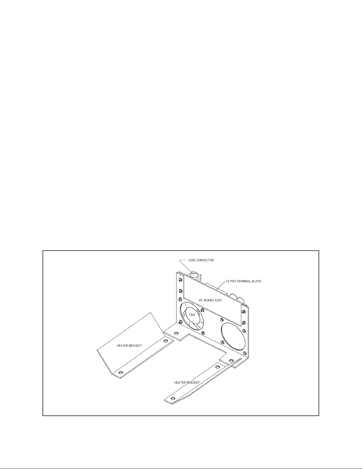
To install the HB6000, HB6000/220, and HB6024 perform the following steps. Refer to Figure 1.
4.1 HEATER ASSEMBLY
1. Open the cover or access door.
2. The heater brackets are designed to attach to two
(2) adjacent studs retaining the window.
3. Remove any two (2) adjacent nuts and washers
(preferably at the bottom of the window) on both
sides of the window.
4. Place the heater brackets on the studs, heaters
angled away from the window, and replace and
tighten the hardware.
1. Open the cover or access door(s).
2. On the HS1000, the blower/PCB bracket is designed to attach to any two (2) adjacent studs retaining the bottom plate. On the HS6000, the
blower/PCB bracket is designed to attach to the
two (2) studs at the bottom of the window.
3. On the HS1000, remove any two (2) adjacent nuts
and washers retaining the bottom plate to the
mounting frame. On the HS6000, remove the nuts
and washers retaining the bottom of the window.
4. Place the blower/PCB bracket over the studs and
replace and tighten the hardware
Figure 1. HB6000, HB6000/220, and HB6024 Assembly
Pelco Manual C496M (12/90) 3
Page 4

4.3 HEATER/BLOWER WIRING
4.4 ELECTRICAL CONNECTION
The blower is factory wired to the PCB assembly.
Connect the heaters to the PCB assembly as shown in
the respective wiring diagrams (refer to Figure 2, Figure 3, or Figure 4).
Supply AC line voltage (230 VAC, 120 VAC, or 24 VAC)
as shown.
After the cable has been routed, all wire connections
should be made (i.e., video, lens, camera power, heaters). A 6-position terminal block has been provided to
assist in this.
CAUTION: When using a single power
source for both the camera and accessories, the
camera power consumption must be taken into
consideration when determining the wire gauge.
Also, make certain that all electrical connections are done properly and meet electrical
codes.
Figure 2. HB6000/220 Heater/Blower Kit Wiring Diagram (230 VAC)
4 Pelco Manual C496M (12/90)
Page 5

Figure 3. HB6000 Heater/Blower Kit Wiring Diagram (120VAC)
Figure 4. HB6024 Heater/Blower Kit Wiring Diagram (24 VAC)
Pelco Manual C496M (12/90) 5
Page 6

5.0 MECHANICAL PARTS LIST FOR HB6000/220 (230 VAC) HEATER/BLOWER KIT
Item No. Qty Description Part Number
1 1 Bracket, Fan/PCB, HB6000 HB60004000COMP
2 1 PCB Assembly, Term/Thermo, EH4500 Series PCB9000256ASSY
3 1 Fan 10CFM 2.36" SQ 115 VAC MM750010003
4 2 Bracket, Heater, HB6000 HB60004001COMP
5 1 Insulator, PCB, EH4500, 6.25" x 2.00" EH450010256
6 2 Heater Blanket 2" x 2" 115V40W EHWD10087
7 1 Resistor 3K Ohm, 10W RES003.0K10.00
MECHANICAL PARTS LIST FOR HB6000 (120 VAC) HEATER/BLOWER KIT
Item No. Qty Description Part Number
1 1 Bracket, Fan/PCB, HB6000 HB60004000COMP
2 1 PCB Assembly, Term/Thermo, EH4500 Series PCB9000256ASSY
3 1 Fan 10CFM 2.36" SQ 115VAC MM750010003
4 2 Bracket, Heater, HB6000 HB60004001COMP
5 1 Insulator, PCB, EH4500, 6.25" x 2.00" EH450010256
6 2 Heater Blanket 2" x 2" 115V40W W/PSA EHWD10087
MECHANICAL PARTS LIST FOR HB6024 (24 VAC) HEATER/BLOWER KIT
Item No. Qty Description Part Number
1 1 Diode Bridge Rectifier 1A400PRV MOT DIOMDA104
2 1 PCB Assy, Term/Thermo, EH4500 Series PCB9000256ASSY
3 1 FAN 11CFM 2.36" SQ. 24VDC, D24-B10TRW ED210005
4 2 Bracket, Heater, HB6000 HB60004001COMP
5 1 Insulator, PCB, EH4500, 6.25" x 2.00" EH450010256
6 2 Heater Blanket 2" x 2" 24V40W W/PSA EHHK10087
7 1 Diode Bridge Rectifier 1A400PRV MOT DIOMDA104
6 Pelco Manual C496M (12/90)
Page 7

6.0 SPECIFICATIONS
ELECTRICAL
Input Voltage: 24 VAC/120 VAC/230 VAC, 50/60 Hz
Electrical
Connection: One 10-position terminal block (in-
put)
One 6-pin lens connector
Two (2) 10-position terminal blocks
for internal wiring
Pelco Manual C496M (12/90) 7
Page 8

7.0 WARRANTY AND RETURN
INFORMATION
WARRANTY
Pelco will repair or replace, without charge, any merchandise proved
defective in material or workmanship for a period of one year after the date
of shipment.
Exceptions to this warranty are as noted below:
• Five years on FT/FR8000 Series fiber optic products.
• Three years on Genex
keyboard).
• Three years on Camclosure
CC3701H-2, CC3701H-2X, CC3751H-2, CC3651H-2X, MC3651H-2,
and MC3651H-2X camera models, which have a five-year warranty.
• Two years on standard motorized or fixed focal length lenses.
• Two years on Legacy
DF5/DF8 Series fixed dome products.
• Two years on Spectra®, Esprit®, ExSite™, and PS20 scanners, includ-
ing when used in continuous motion applications.
• Two years on Esprit
wiper blades).
• Eighteen months on DX Series digital video recorders, NVR300
Series network video recorders, and Endura
network-based video products.
• One year (except video heads) on video cassette recorders (VCRs).
Video heads will be covered for a period of six months.
• Six months on all pan and tilts, scanners or preset lenses used in
continuous motion applications (that is, preset scan, tour and auto scan
modes).
Pelco will warrant all replacement parts and repairs for 90 days from the
date of Pelco shipment. All goods requiring warranty repair shall be sent
freight prepaid to Pelco, Clovis, California. Repairs made necessary by
reason of misuse, alteration, normal wear, or accident are not covered
under this warranty.
Pelco assumes no risk and shall be subject to no liability for damages or
loss resulting from the specific use or application made of the Products.
Pelco’s liability for any claim, whether based on breach of contract,
negligence, infringement of any rights of any party or product liability,
relating to the Products shall not exceed the price paid by the Dealer to
Pelco for such Products. In no event will Pelco be liable for any special,
incidental or consequential damages (including loss of use, loss of profit
and claims of third parties) however caused, whether by the negligence
of Pelco or otherwise.
The above warranty provides the Dealer with specific legal rights. The
Dealer may also have additional rights, which are subject to variation from
state to state.
If a warranty repair is required, the Dealer must contact Pelco at (800)
289-9100 or (559) 292-1981 to obtain a Repair Authorization number
(RA), and provide the following information:
1. Model and serial number
2. Date of shipment, P.O. number, Sales Order number, or Pelco invoice
number
3. Details of the defect or problem If there is a dispute regarding the
warranty of a product which does not fall under the warranty conditions
stated above, please include a written explanation with the product
when returned.
Method of return shipment shall be the same or equal to the method by
which the item was received by Pelco.
®
Series products (multiplexers, server, and
®
and fixed camera models, except the
®
, CM6700/CM6800/CM9700 Series matrix, and
®
and WW5700 Series window wiper (excluding
™
Series distributed
RETURNS
In order to expedite parts returned to the factory for repair or credit, please
call the factory at (800) 289-9100 or (559) 292-1981 to obtain an
authorization number (CA number if returned for credit, and RA number
if returned for repair).
All merchandise returned for credit may be subject to a 20% restocking
and refurbishing charge.
Goods returned for repair or credit should be clearly identified with the
assigned CA or RA number and freight should be prepaid. Ship to the
appropriate address below.
If you are located within the continental U.S., Alaska, Hawaii or Puerto
Rico, send goods to:
Service Department
Pelco
3500 Pelco Way
Clovis, CA 93612-5699
If you are located outside the continental U.S., Alaska, Hawaii or Puerto
Rico and are instructed to return goods to the USA, you may do one of the
following:
If the goods are to be sent by a COURIER SERVICE, send the goods to:
Pelco
3500 Pelco Way
Clovis, CA 93612-5699 USA
If the goods are to be sent by a FREIGHT FORWARDER, send the goods
to:
Pelco c/o Expeditors
473 Eccles Avenue
South San Francisco, CA 94080 USA
Phone: 650-737-1700
Fax: 650-737-0933
This equipment contains electrical or electronic components that must be recycled properly to comply with Directive 2002/96/EC of the European Union
regarding the disposal of waste electrical and electronic equipment (WEEE). Contact your local dealer for procedures for recycling this equipment.
Pelco, the Pelco Logo, Camclosure, Esprit, Genex, Legacy, and Spectra are registered trademarks of Pelco. © Copyright 1990, Pelco. All rights reserved.
Endura and ExSite are trademarks of Pelco.
8 Pelco Manual C496M (12/90)
 Loading...