

Pelco G3512-2PAV5A, G3512-2PAV55AK, G3512-2PAV55A, G3512-2PAV50K, G3512-2PAV50AW User Manual
...
C20-CH Series 650 TV lines
High Resolution Camera
Installation/Operation Manual
18 to 32VAC (Revision A)
C3981M-A-EN (04/14)
Before attempting to connect or operate this product, please read these instructions
carefully and save this manual for future use.
C20-CH series model names:
C20-CH-6(X)
C20-CH-7X
1

CONTENTS
CONTENTS
Important Safety Instructions ................................................................................................................................... 3
Important Notices .................................................................................................................................................. 5
REGULATORY NOTICES [FCC CLASS B] ................................................................................................... 5
RADIO AND TELEVISION INTERFERENCE ............................................................................................... 5
Warranty .............................................................................................................................................................. 5
1. Introduction ............................................................................................................................................................. 6
2. Part Names and Locations................................................................................................................................... 7
3. OSD Menu ............................................................................................................................................................ 10
4. OSD Menu Settings ............................................................................................................................................ 11
4.1 LENS ........................................................................................................................................................... 12
4.2 SHUTTER/AGC ......................................................................................................................................... 12
4.3 WHITE BAL ................................................................................................................................................ 13
4.4 BACKLIGHT ............................................................................................................................................... 14
4.5 PICTURE ADJUST ................................................................................................................................... 14
4.6 ATR* ............................................................................................................................................................ 14
4.7 MOTION DET ............................................................................................................................................ 14
4.8 PRIVACY .................................................................................................................................................... 15
4.9 DAY/NIGHT ................................................................................................................................................ 15
4.10 NR ............................................................................................................................................................. 15
4.11 CAMERA ID ............................................................................................................................................. 16
4.12 SYNC ........................................................................................................................................................ 16
4.13 LANGUAGE ............................................................................................................................................. 16
4.14 CAMERA RESET .................................................................................................................................... 16
4.15 SAVE ALL ................................................................................................................................................ 16
5. Specification ......................................................................................................................................................... 17
Pelco Troubleshooting Contact Information ......................................................................................................... 18
Note for Dimension Drawings ................................................................................................................................ 18
2
C3981M-A-EN (04/14)

Important Safety Instruction
Important Safety Instructions
1. Read these instructions.
2. Keep these instructions.
3. Heed all warnings.
4. Follow all instructions.
5. Do not use this apparatus near water.
6. Clean only with dry cloth.
7. Do not block any ventilation openings. Install in accordance with the manufacturer’s instructions.
8. Do not install near any heat sources such as radiators, heat registers, stoves, or other apparatus (including amplifiers) that
produce heat.
9. Only use attachments/accessories specified by the manufacturer.
10. Use only with the cart, stand, tripod, bracket, or table specified by the manufacturer, or sold with the apparatus. When a cart is
used, use caution when moving the cart/apparatus combination to avoid injury from tip-over.
11. Refer all servicing to qualified service personnel. Servicing is required when the apparatus has been damaged in any way,
such as power-supply cord or plug is damaged, liquid has been spilled or objects have fallen into the apparatus, the apparatus
has been exposed to rain or moisture, does not operate normally, or has been dropped.
12. Apparatus shall not be exposed to dripping or splashing and that no objects filled with liquids, such as vases shall be placed
on the apparatus.
13. WARNING: To reduce the risk of fire or electric shock, do not expose this apparatus to rain or moisture.
14. Installation should be done only by qualified personnel and conform to all local codes.
15. Unless the unit is specifically marked as a NEMA Type 3, 3R, 3S, 4, 4X, 6, or 6P enclosure, it is designed for indoor use only
and it must not be installed where exposed to rain and moisture.
16. Use only installation methods and materials capable of supporting four times the maximum specified load.
3
C3981M-A-EN (04/14)

Important Safety Instruction
This symbol indicates that there are important operating and maintenance instructions in the literature
correctly attach an ESD wrist strap to your wrist and appropriately discharge your body and tools. For
S20.20-1999 or contact the Electrostatic Discharge Association (www.esda.org).
CAUTION: These servicing instructions are for use by qualified service personnel only. To reduce the risk of electric shock do not
perform any servicing other that contained in the operating instructions unless you are qualified to do so.
Only use replacement parts recommended by Pelco.
The product and/or manual may bear the following marks:
This symbol indicates that dangerous voltage constituting a risk of electric shock is present within this unit.
CAUTION: RISK OF ELECTRIC SHOCK. DO NOT OPEN.
accompanying this unit
WARNING: This product is sensitive to Electrostatic Discharge (ESD). To avoid ESD damage to this
product, use ESD safe practices during installation. Before touching, adjusting or handling this product,
more information about ESD control and safe handling practices of electronics, please refer to ANSI/ESD
4
C3981M-A-EN (04/14)

Important Notices
REGULATORY NOTICES [FCC CLASS B]
This device complies with Part 15 of the FCC Rules. Operation is subject to the following two conditions: (1) this device may not
cause harmful interference, and (2) this device must accept any interference received, including interference that may cause
undesired operation.
RADIO AND TELEVISION INTERFERENCE
This equipment has been tested and found to comply with the limits of a Class B digital device, pursuant to Part 15 of the FCC
Rules. These limits are designed to provide reasonable protection against harmful interference in a residential installation. This
equipment generates, uses, and can radiate radio frequency energy and, if not installed and used in accordance with the
instructions, may cause harmful interference to radio communications. However there is no guarantee that the interference will not
occur in a particular installation. If this equipment does cause harmful interference to radio or television reception, which can be
determined by turning the equipment off and on, the user is encouraged to try to correct the interference by one or more of the
following measures:
• Reorient or relocate the receiving antenna.
• Increase the separation between the equipment and the receiver.
• Connect the equipment into an outlet on a circuit different from that to which the receiver is connected.
• Consult the dealer or an experienced radio/TV technician for help.
You may also find helpful the following booklet, prepared by the FCC: “How to Identify and Resolve Radio-TV Interference
Problems.” This booklet is available from the U.S. Government Printing Office, Washington D.C. 20402.
Changes and Modifications not expressly approved by the manufacturer or registrant of this equipment can void your authority to
operate this equipment under Federal Communications Commission’s rules.
This Class B digital apparatus complies with Canadian ICES-003.
Cet appareil numérique de la classe B est conforme à la norme NMB-003 du Canada.
Warranty
For information about Pelco’s product warranty and thereto related information, refer to www.pelco.com/warranty.
Operating Notes:
Warning:
For C20-CH (Revision A); released in 2014:
For dual voltage model: Connect to 12VDC or 18 to 32VAC power adapter.
For high voltage model: Connect to 220VAC power source.
For older C20-CH (prior to Revision A):
For dual voltage model: Connect to 12VDC or 24VAC power adapter.
For high voltage model: Connect to 220VAC power source
.
Operating Conditions
• Avoid viewing very bright objects (example, light fixtures) for extended periods.
• Avoid operating or storing the unit in the following locations:
- Extremely humid, dusty, hot/cold environments
- Close to sources of powerful radio or TV transmitters
- Close to fluorescent lamps or objects reflecting light
- Under unstable light sources (may cause flickering)
Suggested Installation:
Where the operating temperature is outside the recommended range of 14°F
to 122°F [-10°C to +50°C])
5
C3981M-A-EN (04/14)

Introduction
1. Introduction
The box camera is ideal for indoor installation in commercial environment.
Before You Begin:
Please read this guide carefully before you install the box camera. Keep this guide for future reference.
Package Contents:
Check that the items received match those listed on the order form and packing slip. The box camera
packing box includes:
• One
• One fully assembled camera
• One Lens mounting cap
• One Hexagonal and Minus wrench
• One C adapter ring
• One Auto Iris lens connector
If any parts are missing or damaged, contact the dealer you purchased the camera from.
Optional Accessories:
• C10-UM Mount
We recommend that you mount the camera with the C10-UM mount, a C10 series universal
wall/ceiling/rail mounting kit.
installation/operation manual
6
C3981M-A-EN (04/14)

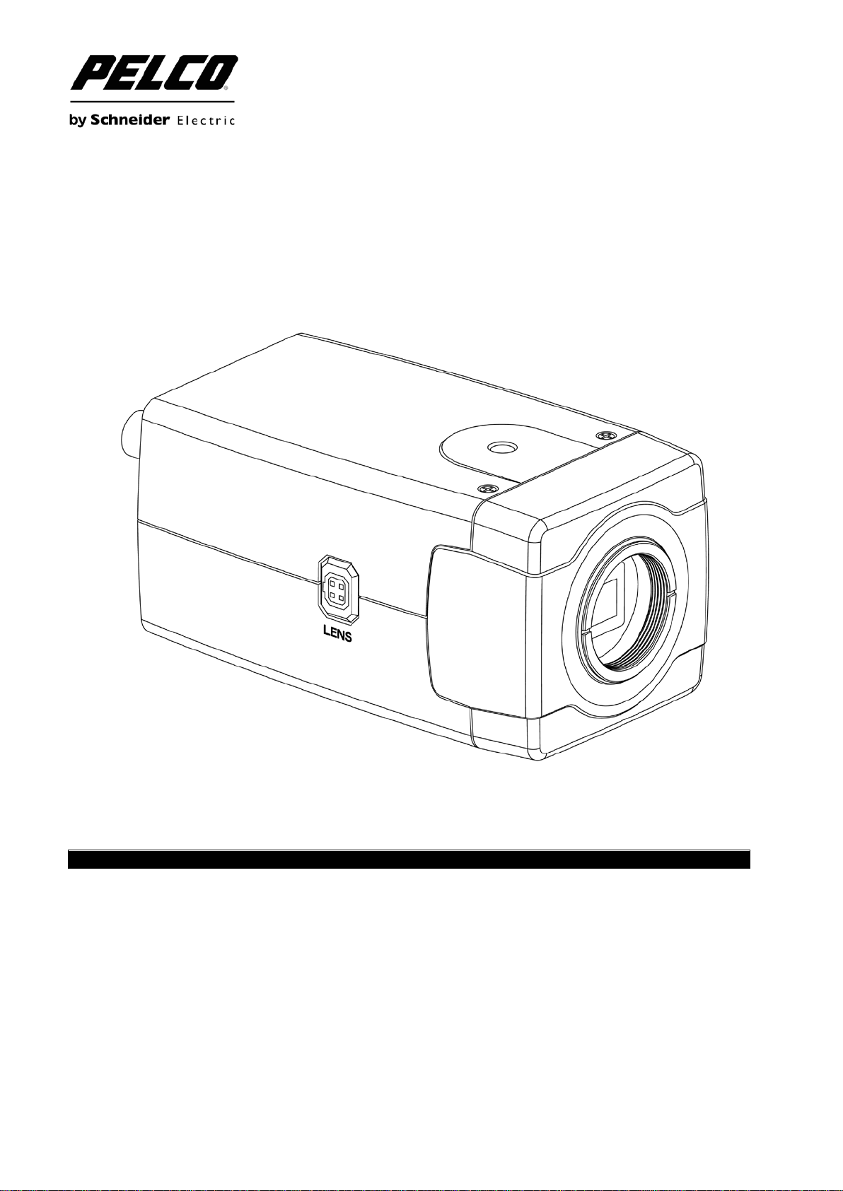
Part Names and Locations
2. Part Names and Locations
Figure 2-1 C20-CH-6/C20-CH-6X
7
C3981M-A-EN (04/14)

Part Names and Locations
Figure 2-2 C20-CH-7X
8
C3981M-A-EN (04/14)

Part Names and Locations
(1) Lens mount C/CS
For the installation of CS Mount lenses only, use
no adapter.
Before mounting the C mount lens, you can
screw the C adapter onto the lens, and then
screw the lens onto the lens mount.
(2) Back Focus adjustment
Use a minus wrench to loosen this screw before
you use the Focus Adjustment. To maintain the
correct focus afterwards, ensure that it is
tightened.
(3) Video Output Ter minal
BNC: Used to give out the video signal.
Connected to the video input terminal of a
monitor, Matrix, etc. (to be terminated with 75
ohm impedance)
(4) OSD joystick control
Press the OSD joystick control straight down:
• For two seconds to enter the Main menu.
• To enter a screen or to select a submenu
option. A selected menu item blinks.
(5) I/O
Connect your external devices to the
corresponding I/O terminal block. The pins of the
I/O terminal block controls the following signals:
TP+/-: UTP (Unshielded Twisted Pair)
(6) Power Connector
Connect to the respective power source.
• For dual-voltage model: Connect to 12VDC or
18 to 32VAC power adapter.
• For high-voltage model: Connect to 220VAC
power source.
WARNING:
This apparatus must be GROUNDED.
(7) Power Indicator
The power indicator light is lit (Red), which
means the power is connected.
(8) Auto Iris lens connector
Supplies power and control signals to an
auto-iris lens.
9
C3981M-A-EN (04/14)

OSD Setup Menu
3. OSD Menu
Set up menu
Lens
AUTO AUTO/Manual
Shutter/AGC
WHITE BAL
Backlight
Pic Adjust
ATR
OFF OFF/ON (Luminance, Contrast)
Motion Det
Privacy
Day/Night
NR
OFF
Camera ID
SYNC
Language
Camera Reset
Exit
Save All
INT INT
Default set Menu
AUTO
ATW ATW/Push Lock/User1/User2/Anti CR/Manual
OFF OFF/BLC/HLC
Option Mirror, Brightness, Contrast, Sharpness, Hue, Gain
OFF OFF/ON (Detect Sense, Block DISP, Motion Area, Area Sel)
OFF OFF/ON (Area Sel, Color, Transp, Mosaic)
AUTO AUTO/BW/Color
OFF OFF/ON
English
AUTO (High Luminance, Low Luminance)/ Manual (Mode,
Shutter, AGC)
NR Mode (Off, Y, C)
Y Level
C Level
ENGLISH / SPANISH / RUSSIAN / GERMAN / FRENCH /
JAPANESE or PORTUGUESE
10
C3981M-A-EN (04/14)

Menu Settings
4. OSD Menu Settings
Entering OSD Menu
Push in on the joystick to open the Main menu. Use the UP/DOWN functions of the joystick to move the
cursor to the item you want to modify. A selected menu item will be highlighted.
Press UP: Press to move the cursor up.
Press Down: Press to move the cursor down.
Enter button: Push in on the joystick to enter the selected item or change the settings of the
selected item.
Press Right: Press to change the settings of the selected item.
Press Left: Press to change the settings of the selected item.
NOTE: When an item is selected, it will be highlighted.
After all the settings have been satisfied, move the cursor to the "Save All" item and press the enter
button. Then move the cursor to the "EXIT" item and press the enter button to exit OSD setup menu.
You can also restore the settings to factory default by moving the cursor to the "CAMERA RESET" item
and then pressing the Enter button. Then move the cursor to the "Save All" item and press the Enter
button.
11
C3981M-A-EN (04/14)

Menu Settings
Use the OSD menu to set up the camera for optimum performance.
LENS AUTO
SHUTTER/AGC AUTO
WHITE BAL ATW
BACKLIGHT OFF
PICT ADJUST
ATR OFF
MOTION DET OFF
NEXT
EXIT SAVE ALL
PRIVACY OFF
DAY/ N I G H T AUTO
NR
CAMERA ID OFF
SYNC INT
LANGUAGE ENGLISH
CAMERA RESET
BACK
EXIT SAVE ALL
4.1 LENS
Select the auto or Manual lens function. The default setting is AUTO (Auto Iris lens). Move the joystick
control LEFT or RIGHT to select Auto or Manual Lens. Enter the AUTO submenu as shown in the figure
below. Move the joystick control UP or DOWN to open, close, or set IRIS to auto mode. Move the joystick
control UP or DOWN to adjust the DC Iris Lens convergence speed.
If speed value is lower, the IRIS will be slower. If speed value is higher, the IRIS will be faster.
TYPE DC
MODE OPEN
SPEED 046
RETURN
4.2 SHUTTER/AGC
Set the shutter speed/AGC (Auto Gain Control) function. The default setting is AUTO. Move the joystick
control LEFT or RIGHT to select AUTO or MANUAL.
SUGGESTED USE:
DC Lens: When using DC lens, We recommend to set SHUTTER/AGC to AUTO mode. Enter the AUTO
submenu as shown in the figure. Move the joystick control UP or DOWN to adjust the HIGH
LUMINANCE MODE to AUTO IRIS.
Manual Lens: When using MANUAL lens, We recommend to set SHUTTER/AGC to AUTO mode. Enter
the AUTO submenu as shown in the figure. Move the joystick control UP or DOWN to adjust the HIGH
LUMINANCE MODE and LOW LUMINANCE setting.
12
C3981M-A-EN (04/14)

Menu Settings
:
RETURN
RETURN
AUTO IRIS and SHUT+AUTO IRIS diff erence
• Use DC lens and setting to AUTO IRIS mode for normal condition application environments. The IRIS
level will be controlled by camera brightness.
• Use DC lens and setting to SHUT+AUTO IRIS mode for high light application environments. The
exposure will be controlled by AES or the DC Iris. The iris level will be controlled by camera brightness.
The shutter speed is variable from 1/50 sec to the 1/10Ksec and the AGC is selectable depending on
your environment condition.
Note
Menu settings for Lens and Shutter/AGC
• When the camera first starts up the menu setting for Lens=Auto (Mode=Auto) and the settings for
Shutter/AGC= High Luminance=Auto Iris
• When you change Lens=Manual then the default settings for Shutter/AGC= High Luminance=Shut
• When you change Lens=Auto then the settings for Shutter/AGC=Shut+AutoIris (this is not the default
value of menu setting when first turned on)
HIGH LUMINANCE
MODE AUTO IRIS
BRIGHTNESS 024
LOW LUMINANCE
MODE AGC
BRIGHTNESS x 0.25
MODE SHUT+AGC
SHUTTER 1/50
AGC 6.0
4.3 WHITE BAL
WHITE BALANCE controls color on the screen. The default is ATW. The color temperature range is
2500°K~ 9500°K. Move the joystick control LEFT or RIGHT to select ATW (Auto White Balance), PUSH,
PUSH LOCK, USER1, USER2, Anti CR (Anti Color Rolling Suppression) or MANUAL mode. Enter the
ATW submenu as shown in the figure. Move the joystick control UP or DOWN to select the desired
value. Select ATW (Auto White Balance) when the scene illumination varies between indoor scenes and
outdoor scene lighting.
NOTE:
When setting different values of the ATW FRAME and the application environment, the color
temperature range of white balance will be changed. The color temperature range of x0.50 of ATW
FRAME will be smaller than x2.00.
SPEED 171
DE L AY CNT 152
If you select MANUAL mode, you can adjust the LEVEL from 17 to 54.
If you select USER1 or USER2 mode, you can adjust B-GAIN and R-GAIN value from 0 to 255.
If you select PUSH mode in the appropriate position, the whole area will perform white balance.
If you select PUSH LOCK mode in the appropriate position, WHITE BALANCE will perform once.
If you select Anti CR mode in the appropriate position, the whole area will effectively restrain color cast.
ATW FRAME x 0.50
ENVIRONMENT INDOOR
13
C3981M-A-EN (04/14)

Menu Settings
RETURN
RETURN
RETURN
4.4 BACKLIGHT
Set the backlight compensation function. The default is OFF. Move the joystick control LEFT or RIGHT
to select OFF, BLC or HLC (Highlight Compensation) mode. When you switch to BLC, the function
controls the light level to overcome severe backlighting conditions. HLC activated automatically
depending on the shooting condition (detects night and high-luminance)
BLC and HLC Compensation are the functions that achieve the brightness of a selected area to an
optimum image level. Due to the intense light coming from the back of objects in the area you want to
view, the auto iris lens tends to close and areas you want to see become dark and invisible.
4.5 PICTURE ADJUST
Set the PICTURE ADJUST function. Enter the PICT ADJUST submenu as shown in the figure below.
Move the joystick control UP or DOWN to set picture Brightness, Contrast, Sharpness, Hue, or Gain
value. In addition, you can set MIRROR to the ON mode then the picture to be left or right.
MIRROR OFF
BRIGHTNESS 000
CONTRAST 128
SHARPNESS 128
HUE 128
GAIN 128
4.6 ATR*
Set the ATR (Adaptive Tone-curve Reproduction) function. The default is OFF. Move the joystick control
LEFT or RIGHT to select the ON mode then enter to the ATR submenu, you can set LUMINACE and
CONTRAST to optimize by image.
*Also known as Wide Dynamic Range. This function expands the video dynamic range of the camera
and improves visibility of images even in high contrast environments.
LUMINANCE LOW
CONTRAST LOW
4.7 MOTION DET
Set the Motion Detection function. MOTION DET allows detecting moving objects on the screen. The
default is OFF. Move the joystick control LEFT or RIGHT to select the ON mode then enter to the
MOTION DET submenu. You can set 4 motion areas to detect moving objectives and adjust the motion
detection sensitivity. Use the LEFT/RIGHT functions of the joystick control to set the sensitivity from 000
to 127.
DETECT SENSE 100
BLOCK DISP OFF
MONITOR AREA OFF
AREA SEL 1/4
TOP 000
BOTTOM 000
LEFT 000
RIGHT 000
14
C3981M-A-EN (04/14)

Menu Settings
RETURN
RETURN
4.8 PRIVACY
Set the PRIVACY function. The default setting is OFF. Move the joystick control LEFT or RIGHT to
select the ON mode then enter to the PRIVACY submenu. You can configure 8 privacy positions, set 8
privacy areas, choose different color zone and set transparency of 8 privacy zone. However if you
enable MOTION DET function, then the PRIVACY function will support only 4 zones. In addition, the
image of PRIVACY can allow you to set the MOSAIC function.
R E A S E L 1/8
TOP 000
BOTTOM 000
LEFT 000
RIGHT 000
COLOR 1
TRANSP 0.00
MOSAIC OFF
RETURN
4.9 DAY/NIGHT
Set the DAY/NIGHT function. The default setting is AUTO. Move the joystick control LEFT or RIGHT to
select the AUTO, COLOR, BW mode. Enter the AUTO submenu as shown in the figure below. Move the
joystick control UP or DOWN to adjust the BURST value and set the time before the camera switches to
DAY-> NIGHT mode or NIGHT->DAY mode.
When select Day->NIGHT level to set up switchover point of brightness from COLOR mode to B/W mode
under different Lux levels.
When select NIGHT->DAY level to set up switchover point of brightness from B/W mode to COLOR
mode under different Lux levels.
BURST OFF
DELAY CNT 100
DAY->NIGHT 100
NIGHT->DAY 100
If you select COLOR mode, you can force the camera to stay in DAY (COLOR) mode.
If you select BW mode, you can force the camera to stay in BW (NIGHT) mode. The BW submenu
allows you to select BURST to be ON or OFF.
4.10 NR
You can configure the 2D DNR (Digital Noise Reduction) settings and reduce noise on the screen. Enter
the NR submenu as shown in the figure below. Move the joystick control UP or DOWN to set the NR
MODE. When you enable the NR MODE to the Y (BRIGHT) / C (COLOR), C LEVEL or Y LEVEL mode,
you can adjust Y LEVEL or C LEVEL depending on your environment condition.
NOTE: When the Y Level is higher the noise in dark areas decreases. Also, resolution will become lower.
When it is lower, there is more noise in dark areas.
NR MODE Y/C
Y LEVEL 000
C LEVEL 000
15
C3981M-A-EN (04/14)

Menu Settings
When the C Level is higher the noise in dark areas becomes lessened. Also, resolution will become
lower. When it is lower, there is more noise in dark areas.
In the dark environment, you can adjust the value higher of Y Level to reduce the dark noise; adjust the
value higher of C Level to reduce the color noise.
4.11 CAMERA ID
CAMERA ID displays ON or OFF. The default setting is OFF. You can set the ON mode to add a camera
title up to 26 characters with 2 lines and also select where the title appears on the monitor screen.
4.12 SYNC
The default setting is INT. This has no adjustment.
4.13 LANGUAGE
OSD supports 6 available languages. The default setting is English. Move the joystick control LEFT or
RIGHT to select the ENGLISH / SPANISH / RUSSIAN / GERMAN / FRENCH / JAPANESE or
PORTUGUESE.
4.14 CAMERA RESET
Move to the CAMERA RESET mode then Press the ENTER key to recall factory settings.
4.15 SAVE ALL
Save all settings and exit.
16
C3981M-A-EN (04/14)

Specification
Camera System Type
C20-CH-6
C20-CH-6X
C20-CH-7X
Format
NTSC
PAL
Optical System
Electric
Sync System
Internal
Lens Mount
CS
Lens Drive
DC
Horizontal Resolution
650 TV lines
f/1.2; 2,850°K; 30IRE
Mono (17 ms) 0.25 Lux
f/1.2; 2,850°K; 30IRE
Mono (20 ms) 0.25 Lux
default 48dB
Auto: 1/50~1/10,000
AGC
Off/On 35dB
White Balance
ATW/Push Lock/Manual/Anti CR/User2/User/Push
BLC
Off/ BLC/ HLC(High Light compensation) (selectable)
WDR
On / Off (selectable, ATR)
Noise Reduction-DNR
2D
Motion Detection
Yes
Privacy Zones
Yes
CAMERA ID
Yes
Connection/Termination
Set Up/OSD Input Device
Input Buttons/5 Way Rocker
UTP
Yes
Environment
14°F (-10°C) Minimum,
122°F (50°C) Maximum
Operating humidity
20~90% non-condensing
Mechanism
Construction
Diecast
Dimension (L W H)
60mm X55mm X108mm
5. Specification
Imager Size 1/3"
Sensitivity
S/N Ratio
Shutter
Color Correction With White Balance
Multi Language
Power supply
Power
Power Consumption (Max) 3.5W 4W
Color (17 ms) 0.25 Lux
>52dB by parameter adjustment
Auto: 1/60~1/10,000 Manual:
1/60~10,000
Terminal Strip - Removable
English, Russian, German,
French, Spanish, Japanese
18 to 32 VAC 50/60 Hz/12 VDC +10% to -15%
(Revision A)
Color (20 ms) 0.25 Lux
Manual: 1/50~10,000
English, Russian, German, French,
Spanish, Portuguese
220VAC, +10/-15%
Operating Temperature Range
Weight (unit) 300g 450g
Power LED Red-Rear Panel
17
C3981M-A-EN (04/14)

Troubleshooting Information
Pelco Troubleshooting Contact Information
If the instructions provided fail to solve your problem, contact Pelco Product Support at 1-800-289-9100 (USA and Canada)
or +1-559-292-1981 (international) for assistance. Be sure to have the serial number available when calling.
Do not try to repair the unit yourself. Leave maintenance and repairs to qualified technical personnel only.
This equipment contains electrical or electronic components that must be recycled
properly to comply with Directive 2002/96/EC of the European Union regarding the
disposal of waste electrical and electronic equipment (WEEE). Contact your local
dealer for procedures for recycling this equipment.
REVISION HISTORY
Manual # Date Comments
C3902M 02/14 Original Version
C3981M-A 04/14
Pelco, the Pelco logo, and ot her trademarks associated with Pelco products referred to in this publicat ion are trademarks of Pelco, Inc. or its a ffiliates. © Copy right 2014, Pelco, Inc.
ONVIF and the ONVIF logo a re trademarks of ONVIF Inc. A ll other product names and s ervices are the property of their respective companies. All right s reserved.
Product specifications and availabi lity are subject to change without notice.
18
C3981M-A-EN (04/14)
Revision A

19
 Loading...