

Page 1
INSTALLATION
Esprit® Enhanced IP Positioning System
Esprit Enhanced (ES6230) Models
C1354M (11/17)
Page 2

Contents
Contents. . . . . . . . . . . . . . . . . . . . . . . . . . . . . . . . . . . . . . . . . . . . . . . . . . . . . . . . . . . . . . . . . . . . . . . . . . . . . . . . . . . . . . . . . . . . . . . . . . . . . . . . . . . . . 2
Important Notices . . . . . . . . . . . . . . . . . . . . . . . . . . . . . . . . . . . . . . . . . . . . . . . . . . . . . . . . . . . . . . . . . . . . . . . . . . . . . . . . . . . . . . . . . . . . . . . . . . . . . 3
Legal Notice . . . . . . . . . . . . . . . . . . . . . . . . . . . . . . . . . . . . . . . . . . . . . . . . . . . . . . . . . . . . . . . . . . . . . . . . . . . . . . . . . . . . . . . . . . . . . . . . . . . . . 3
Regulatory Notices . . . . . . . . . . . . . . . . . . . . . . . . . . . . . . . . . . . . . . . . . . . . . . . . . . . . . . . . . . . . . . . . . . . . . . . . . . . . . . . . . . . . . . . . . . . . . . . . 3
Warranty Statement . . . . . . . . . . . . . . . . . . . . . . . . . . . . . . . . . . . . . . . . . . . . . . . . . . . . . . . . . . . . . . . . . . . . . . . . . . . . . . . . . . . . . . . . . . . . . . . 3
Video Quality Caution . . . . . . . . . . . . . . . . . . . . . . . . . . . . . . . . . . . . . . . . . . . . . . . . . . . . . . . . . . . . . . . . . . . . . . . . . . . . . . . . . . . . . . . . . . . . . . 3
Open Source Software Notice . . . . . . . . . . . . . . . . . . . . . . . . . . . . . . . . . . . . . . . . . . . . . . . . . . . . . . . . . . . . . . . . . . . . . . . . . . . . . . . . . . . . . . . 3
Description. . . . . . . . . . . . . . . . . . . . . . . . . . . . . . . . . . . . . . . . . . . . . . . . . . . . . . . . . . . . . . . . . . . . . . . . . . . . . . . . . . . . . . . . . . . . . . . . . . . . . . . . . . . 4
System Model Numbers . . . . . . . . . . . . . . . . . . . . . . . . . . . . . . . . . . . . . . . . . . . . . . . . . . . . . . . . . . . . . . . . . . . . . . . . . . . . . . . . . . . . . . . . . . . 4
Supplied Parts List . . . . . . . . . . . . . . . . . . . . . . . . . . . . . . . . . . . . . . . . . . . . . . . . . . . . . . . . . . . . . . . . . . . . . . . . . . . . . . . . . . . . . . . . . . . . . . . . 4
Installation Tools and Parts Not Supplied . . . . . . . . . . . . . . . . . . . . . . . . . . . . . . . . . . . . . . . . . . . . . . . . . . . . . . . . . . . . . . . . . . . . . . . . . . . . . . 4
Installation . . . . . . . . . . . . . . . . . . . . . . . . . . . . . . . . . . . . . . . . . . . . . . . . . . . . . . . . . . . . . . . . . . . . . . . . . . . . . . . . . . . . . . . . . . . . . . . . . . . . . . . . . . . 5
Overhead Clearance Provisions . . . . . . . . . . . . . . . . . . . . . . . . . . . . . . . . . . . . . . . . . . . . . . . . . . . . . . . . . . . . . . . . . . . . . . . . . . . . . . . . . . . . . . 5
Installing the 24 VAC/48 DC/HPOE Power Module . . . . . . . . . . . . . . . . . . . . . . . . . . . . . . . . . . . . . . . . . . . . . . . . . . . . . . . . . . . . . . . . . . . . . . . 6
Installing the 100-240 VAC Power Module . . . . . . . . . . . . . . . . . . . . . . . . . . . . . . . . . . . . . . . . . . . . . . . . . . . . . . . . . . . . . . . . . . . . . . . . . . . . . 8
Connecting AUX (Optional) . . . . . . . . . . . . . . . . . . . . . . . . . . . . . . . . . . . . . . . . . . . . . . . . . . . . . . . . . . . . . . . . . . . . . . . . . . . . . . . . . . . . . . . . . 10
Installing and Removing an SD Card . . . . . . . . . . . . . . . . . . . . . . . . . . . . . . . . . . . . . . . . . . . . . . . . . . . . . . . . . . . . . . . . . . . . . . . . . . . . . . . . . 11
Installing the Pan and Tilt Module . . . . . . . . . . . . . . . . . . . . . . . . . . . . . . . . . . . . . . . . . . . . . . . . . . . . . . . . . . . . . . . . . . . . . . . . . . . . . . . . . . . 12
2 C1354M (11/17)
Page 3

Important Notices
LEGAL NOTICE
SOME PELCO EQUIPMENT CONTAINS, AND THE SOFTWARE ENABLES, AUDIO/VISUAL AND RECORDING CAPABILITIES, THE IMPROPER USE OF
WHICH MAY SUBJECT YOU TO CIVIL AND CRIMINAL PENALTIES. APPLICABLE LAWS REGARDING THE USE OF SUCH CAPABILITIES VARY
BETWEEN JURISDICTIONS AND MAY REQUIRE, AMONG OTHER THINGS, EXPRESS WRITTEN CONSENT FROM RECORDED SUBJECTS. YOU
ARE SOLELY RESPONSIBLE FOR INSURING STRICT COMPLIANCE WITH SUCH LAWS AND FOR STRICT ADHERENCE TO ANY/ALL RIGHTS OF
PRIVACY AND PERSONALTY. USE OF THIS EQUIPMENT AND/OR SOFTWARE FOR ILLEGAL SURVEILLANCE OR MONITORING SHALL BE DEEMED
UNAUTHORIZED USE IN VIOLATION OF THE END USER SOFTWARE AGREEMENT AND RESULT IN THE IMMEDIATE TERMINATION OF YOUR
LICENSE RIGHTS THEREUNDER.
REGULATORY NOTICES
This device complies with Part 15 of the FCC Rules. Operation is subject to the following two conditions: (1) this device may not cause harmful
interference, and (2) this device must accept any interference received, including interference that may cause undesired operation.
RADIO AND TELEVISION INTERFERENCE
This equipment has been tested and found to comply with the limits of a Class A digital device, pursuant to Part 15 of the FCC rules. These limits
are designed to provide reasonable protection against harmful interference when the equipment is operated in a commercial environment.
This equipment generates, uses, and can radiate radio frequency energy and, if not installed and used in accordance with the instruction manual,
may cause harmful interference to radio communications. Operation of this equipment in a residential area is likely to cause harmful interference
in which case the user will be required to correct the interference at his own expense.
Changes and Modifications not expressly approved by the manufacturer or registrant of this equipment can void your authority to operate this
equipment under Federal Communications Commission’s rules.
CAN ICES-3 (A)/NMB-3(A)
WARRANTY STATEMENT
For information about Pelco’s product warranty and thereto related information, refer to www.pelco.com/warranty.
VIDEO QUALITY CAUTION
Frame Rate Notice Regarding User-Selected Options
Pelco systems are capable of providing high quality video for both live viewing and playback. However, the systems can be used in lower quality
modes, which can degrade picture quality, to allow for a slower rate of data transfer and to reduce the amount of video data stored. The picture
quality can be degraded by either lowering the resolution, reducing the picture rate, or both. A picture degraded by having a reduced resolution
may result in an image that is less clear or even indiscernible. A picture degraded by reducing the picture rate has fewer frames per second,
which can result in images that appear to jump or move more quickly than normal during playback. Lower frame rates may result in a key event
not being recorded by the system.
Judgment as to the suitability of the products for users’ purposes is solely the users’ responsibility. Users shall determine the suitability of the
products for their own intended application, picture rate and picture quality. In the event users intend to use the video for evidentiary purposes in
a judicial proceeding or otherwise, users should consult with their attorney regarding any particular requirements for such use.
OPEN SOURCE SOFTWARE NOTICE
This product includes certain open source or other software originated from third parties that is subject to the GNU General Public License (GPL),
GNU Library/Lesser General Public License (LGPL) and different and/or additional copyright licenses, disclaimers, and notices.
The exact terms of GPL, LGPL, and some other licenses are provided to you with this product. Please refer to the exact terms of the GPL and LGPL
at http://www.fsf.org (Free Software Foundation) or http://www.opensource.org (Open Source Initiative) regarding your rights under said license.
You may obtain a complete corresponding machine-readable copy of the source code of such software under the GPL or LGPL by sending your
request to digitalsupport@pelco.com; the subject line should read Source Code Request. You will then receive an email with a link for you to
download the source code.
This offer is valid for a period of three (3) years from the date of the distribution of this product by Pelco.
C1354M (11/17) 3
Page 4

Description
The Esprit® Enhanced Series network positioning system features a built-in, Web-based viewer for live video streaming to a standard Web
browser (for example, Microsoft® Internet Explorer® or Mozilla® Firefox®).
The system features open architecture connectivity to third-party software. Pelco offers an application programming interface (API) and software
development kit (SDK) that enables third-party systems to interface with Pelco's IP systems. The Esprit Enhanced Series is also compatible with
VideoXpert, Endura
Operating Temperature Range:
–45° to 60°C (–50° to 140°F) ambient for sustained system operation or 74°C (165.2°F) absolute maximum ambient per NEMA TS-2; within two
hours after power-up, the entire unit can de-ice and be operational from a temperature of –25°C (–13°F). Cold start from –40°C.
SYSTEM MODEL NUMBERS
®
(2.0 or later), and Digital Sentry® systems to record, manage, configure, and view multiple live streams.
Enclosure Type
Standard ES6230-02 ES6230-05 — —
With Wiper ES6230-12 ES6230-15 ES6230-12-R2
Pressurized and Wiper ES6230-12P ES6230-15P ES6230-12P-R2 ES6230-15P-R2
HPoE, 24 VAC, 48 VDC 100 to 240 VAC 48 VDC 100 to 240 VAC
Non IR 200m IR
SUPPLIED PARTS LIST
Qty Description
1 Screw connector (all models)
3 1/4-20 nuts and washers
1 Snap-on cable ferrite
1 Grounding lug
1 Screw for grounding lug
1 20-pin terminal plug for AUX
INSTALLATION TOOLS AND PARTS NOT SUPPLIED
Qty Description
1Network cable
1 Phillips screwdriver
1 Standard flat head screwdriver
17/16-inch wrench
1 Esprit mount
1 Mounting hardware
1 5/32-inch hex bit or Allen key
ES6230-15-R2
USING THE WEB INTERFACE
You can find information about the web interface for your camera on www.pelco.com.
4 C1354M (11/17)
Page 5
Installation
90º
40º
24.6
(9.69)
43.65
(17.19)
16.67
(6.56)
9.29
(3.66)
10.26
(4.04)
10.26
(4.04)
11.50
(4.53)
47.63
(18.75)
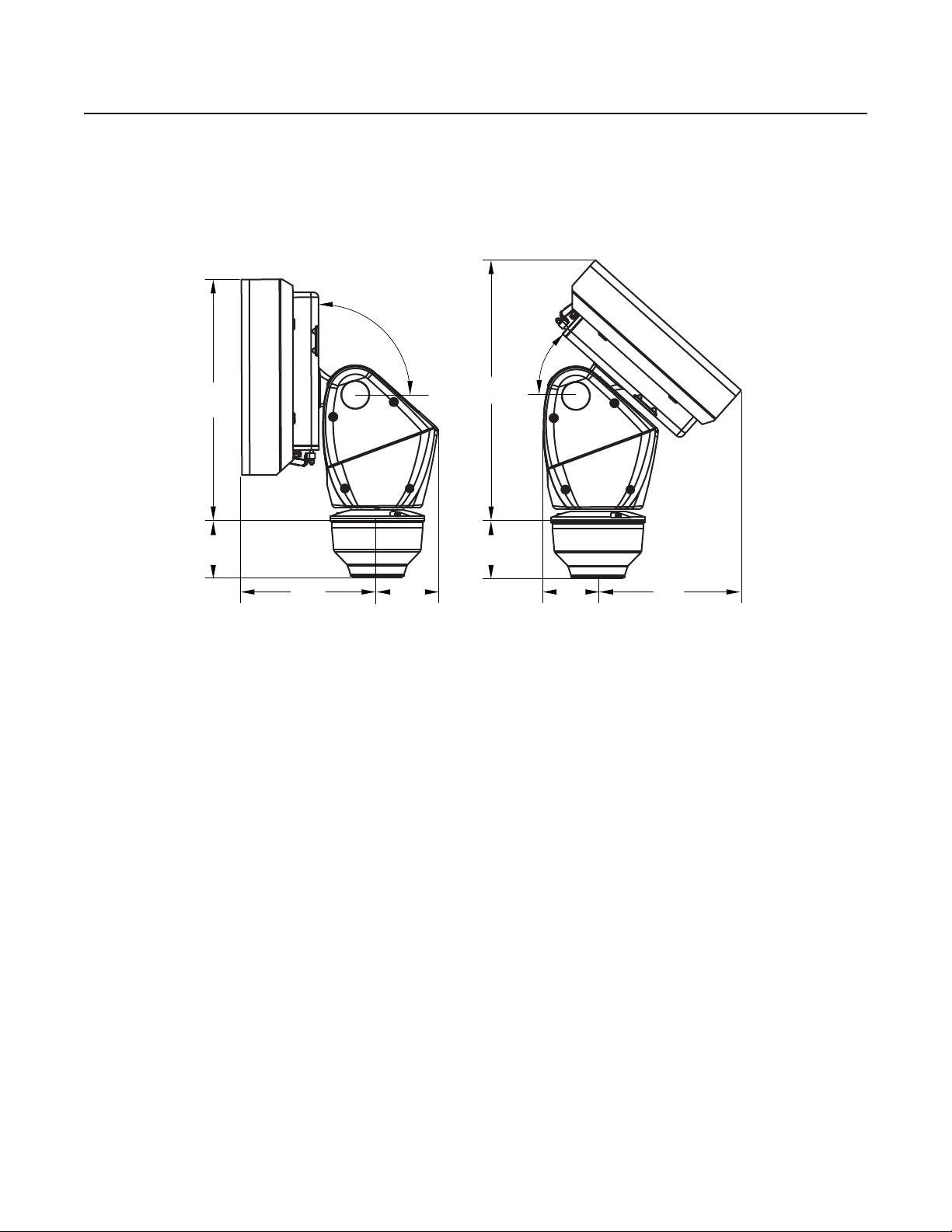
OVERHEAD CLEARANCE PROVISIONS
When installing the Esprit Enhanced system, allow for sufficient clearance between the top of the unit and overhead obstructions. This will
prevent interference when the enclosure is driven to its maximum elevation of 40 degrees.
Figure 1. Clearance for Overhead Obstruction
C1354M (11/17) 5
Page 6

INSTALLING THE 24 VAC/48 DC/HPOE POWER MODULE
MOUNT
MOUNTING HOLES
BASE
MOUNTING
SCREWS
1. Install the Esprit mount; refer to the installation manual supplied with the mount for instructions.
2. Remove the power module assembly from the base of the device by loosening the three Phillips screws and lifting the module.
Figure 2. Removing the 24 VAC /48 DC/HPoE Power Module Assembly
ì
Power Module Assembly
î
Base
3. Attach the base of the device to an Esprit mount:
a. Align the mounting holes on the base with the holes on the mount.
b. Attach the base of the device to the mount using the three flathead screws supplied with EPP2 and EWM mounts.
Figure 3. Attaching the Base to a Mount
6 C1354M (11/17)
Page 7

4. Route the wires and network cable through the center of the Esprit mount.
5. Connect power using the supplied 2-pin screw connector using 16-20 AWG wire gauge. Connect the Cat5e cable to the RJ-45 connector
and/or connect the SFP module(s). Connect AUX (optional). Refer to Connecting AUX (optional) on page 10.
Figure 4. Wiring Connections: 24 VAC
ì
Connects 24 VAC or 48 DC power to the system
î
Connects HPoE power to the system and connects the system to IP network
ï
Connects 1 or 2 SFP modules
Connects up to 2 relays, 4 alarms, audio, and reset using 20-26 AWG wire
Power Wire Description
Label Function
+ +24 VAC or +48 VDC
- -24 VAC, -48VDC, or DC GND
6. Attach the included ferrite to the network cable as close as possible to the RJ-45 connector to reduce radio frequency electrical
interference on the network cable. The cable should have one turn/loop around the ferrite core.
7. Reinstall the power module assembly into the base. The power module assembly can be positioned in the mount base in only one
orientation.
Figure 5. Reinstalling the Power Module
C1354M (11/17) 7
Page 8

8. Turn on the power. If the light turns on, turn off the power, and proceed with installation.
MOUNT
MOUNTING HOLES
BASE
MOUNTING
SCREWS
INSTALLING THE 100-240 VAC POWER MODULE
NOTES:
– The AC Mains unit shall be connected to a two pole circuit breaker rated maximum 15A or 20A.
– This product requires a surge protector device (SPD) or surge arrestor as part of the installation to address transient overvoltages
exceeding Overvoltage Category II, 2500 Vpk.
– High voltage wires must be covered by 0.4 mm thick UL recognized tubing.
– Ethernet and AUX cables must be covered by 0.4 mm thick UL recognized tubing.
1. Make sure your power is turned off while connecting the power module.
2. Remove the power module from the base of the device by loosening the three Phillips screws and lifting the module.
Figure 6. Removing the Power Module
3. Attach the base of the device to an Esprit mount (EWM or EPP2) using the three flathead screws supplied with the EPP2 and EWM mounts.
Figure 7. Attaching the Base to a Mount
8 C1354M (11/17)
Page 9

Figure 8. Wiring Connections: 100 to 240 VAC
ì
Connects 100 to 240 VAC power to the system
î
Connects the system to IP network
ï
Connects 1 or 2 SFP modules
Connects up to 2 relays, 4 alarms, audio, and reset using 16-20 AWG wire
4. Route the wires and cables through the center of the Esprit mount. Reinstall the power module into the base. The power module can be
positioned in the mount base in only one orientation.
Figure 9. Reinstalling the Power Module
5. Connect wires and cables.
a. Connect to power. Use the supplied 2-pin screw connector to connect the AC line and neutral using 16 AWG wire. Use the supplied
grounding lug and screw to connect Ground to the unit using 12-16 AWG wire.
Power Wire Description
Label Function
L Line
C1354M (11/17) 9
Page 10

b. Connect the Cat5e cable to the RJ-45 connector and/or connect SFP module(s). Attach the included ferrite to the network cable as
close as possible to the RJ-45 connector to reduce radio frequency electrical interference on the network cable. The cable should
have one turn/loop around the ferrite core.
c. Connect AUX (optional). Refer to Connecting to Aux (below).
6. Install mount; refer to the installation manual supplied with the mount for instructions.
7. Turn on the power. If the light turns on, turn off the power, and proceed with installation.
CONNECTING AUX (OPTIONAL)
Power Wire Description
Label Function
N Neutral
Earth Ground
Figure 10. Wiring Connections: 100 to 240 VAC
ì
Connects 100 to 240 VAC power to the system
î
Connects the system to IP network
ï
Connects 1 or 2 SFP modules
Connects up to 2 relays, 4 alarms, audio, and reset using 20-26 AWG wire
Relay, Alarm, Audio, and Reset Connections
Designation Function
Relay 2 N.C.
Relays
Alarms
R2
R1
A1 Alarm 1
A2 Alarm 2
A3 Alarm 3
A4 Alarm 4
Relay 2 COM
Relay 2 N.O.
Relay 1 N.C.
Relay 1 COM
Relay 1 N.O.
Reset
10 C1354M (11/17)
Page 11

Relay, Alarm, Audio, and Reset Connections
Audio
Note: All relays are specified for 32 VDC, 0 to 20mA (signal only).
INSTALLING AND REMOVING AN SD CARD
NOTE: It is recommended to power down the unit before installing an SD card, but this is not necessary. You should use an unformatted SD card
for best results.
1. Unscrew the two screws on the camera enclosure (See #3 in Figure 11) using a 5/32-inch hex bit (not supplied) to open the lid.
2. Insert/remove the SD card into/from the connector located behind the camera (See #2 in Figure 11) (NOTE: Orientation of the SD card as
identified by the label on the panel.).
Designation Function
Audio In
Audio Out
Figure 11. SD Card Installation
ì
Reset button* (Reboots the camera or restores the camera’s factory default
settings.)
î
SD card slot
ï
Lid screws
*When the Esprit unit is reset, it will go through a calibration causing the unit to move.
3. Close the lid and tighten the screws.
C1354M (11/17) 11
Page 12

INSTALLING THE PAN AND TILT MODULE
1. Connect the male system connector, located on the bottom of the pan/tilt, to the female system connector, located on the transformer and
power module.
2. Align the screw hole of the pan/tilt with the stud of the power module.
3. Attach the pan/tilt to the base with three 1/4-20 nuts and washers (supplied).
NOTICE: When installing the pan/tilt, avoid damaging the base gasket and male system connector cable during installation. Damaging the gasket
may create a water ingress point, which could cause the gasket to leak.
Figure 1. Installing the Pan/Tilt Module
ì
Male System Connector
î
Female System Connector
ï
Base Gasket
REVISION HISTORY
Manual # Date Comments
C1354M 11/17 Original version.
Pelco, the Pelco logo, and other trademarks associa ted with Pelco products referred to in this publication are trademarks of Pelco, Inc. or its affilia tes. © Copyright 2017, Pelco, Inc.
ONVIF and the ONVIF logo are trademarks of ONVIF Inc. All other product names and services are the property of their respective companies. All rights reserved.
Product specifications and availability are subject to change without notice.
12 C1354M (11/17)
Page 13

C1354M (11/17) 13
Page 14

Pelco by Schneider Electric 625 Alluvial Fresno, California 93711 United States
USA & Canada Tel (800) 289-9100 Fax (800) 289-9150
International Tel +1 (559) 292-1981 Fax +1 (559) 348-1120
www.pelco.com www.pelco.com/community
 Loading...