

Page 1
OPERATION/PROGRAMMING
ES30-ISAP
®
Pan and Tilt System
C312M-A (12/02)
Page 2

CONTENTS
Section Page
DESCRIPTION . . . . . . . . . . . . . . . . . . . . . . . . . . . . . . . . . . . . . . . . . . . . . . . . . . . . . . . . . . . . . . . . . . . . . . . . . . . . . . . . . . . . . . . . . . . . . . . . . . . . . . . . . . . . 4
MODELS . . . . . . . . . . . . . . . . . . . . . . . . . . . . . . . . . . . . . . . . . . . . . . . . . . . . . . . . . . . . . . . . . . . . . . . . . . . . . . . . . . . . . . . . . . . . . . . . . . . . . . . . . . . 4
INSTALLATION . . . . . . . . . . . . . . . . . . . . . . . . . . . . . . . . . . . . . . . . . . . . . . . . . . . . . . . . . . . . . . . . . . . . . . . . . . . . . . . . . . . . . . . . . . . . . . . . . . . . . . . . . . . 5
POD 100 . . . . . . . . . . . . . . . . . . . . . . . . . . . . . . . . . . . . . . . . . . . . . . . . . . . . . . . . . . . . . . . . . . . . . . . . . . . . . . . . . . . . . . . . . . . . . . . . . . . . . . . . . . . . 5
PAN AND TILT . . . . . . . . . . . . . . . . . . . . . . . . . . . . . . . . . . . . . . . . . . . . . . . . . . . . . . . . . . . . . . . . . . . . . . . . . . . . . . . . . . . . . . . . . . . . . . . . . . . . . . . 6
TXB SERIES TRANSLATOR BOARD INSTALLATION (OPTIONAL) . . . . . . . . . . . . . . . . . . . . . . . . . . . . . . . . . . . . . . . . . . . . . . . . . . . . . . . . . . . . . . . . . . . . . 9
HOW TO REMOVE THE PAN AND TILT COVER . . . . . . . . . . . . . . . . . . . . . . . . . . . . . . . . . . . . . . . . . . . . . . . . . . . . . . . . . . . . . . . . . . . . . . . . . . . . . . 9
HOW TO REINSTALL THE PAN AND TILT COVER . . . . . . . . . . . . . . . . . . . . . . . . . . . . . . . . . . . . . . . . . . . . . . . . . . . . . . . . . . . . . . . . . . . . . . . . . . . . 9
CAMERA OPERATION (POD 100 THERMAL IMAGER) . . . . . . . . . . . . . . . . . . . . . . . . . . . . . . . . . . . . . . . . . . . . . . . . . . . . . . . . . . . . . . . . . . . . . . . 11
OPERATION. . . . . . . . . . . . . . . . . . . . . . . . . . . . . . . . . . . . . . . . . . . . . . . . . . . . . . . . . . . . . . . . . . . . . . . . . . . . . . . . . . . . . . . . . . . . . . . . . . . . . . . . . . . . . 11
POWER-UP DISPLAY . . . . . . . . . . . . . . . . . . . . . . . . . . . . . . . . . . . . . . . . . . . . . . . . . . . . . . . . . . . . . . . . . . . . . . . . . . . . . . . . . . . . . . . . . . . . . . . . . 11
PAN AND TILT OPERATION . . . . . . . . . . . . . . . . . . . . . . . . . . . . . . . . . . . . . . . . . . . . . . . . . . . . . . . . . . . . . . . . . . . . . . . . . . . . . . . . . . . . . . . . . . . . 11
OPERATING NOTES . . . . . . . . . . . . . . . . . . . . . . . . . . . . . . . . . . . . . . . . . . . . . . . . . . . . . . . . . . . . . . . . . . . . . . . . . . . . . . . . . . . . . . . . . . . . . . . . . . 12
ENVIRONMENTAL RANGE . . . . . . . . . . . . . . . . . . . . . . . . . . . . . . . . . . . . . . . . . . . . . . . . . . . . . . . . . . . . . . . . . . . . . . . . . . . . . . . . . . . . . . . . 12
PAN AND TILT FUNCTIONS . . . . . . . . . . . . . . . . . . . . . . . . . . . . . . . . . . . . . . . . . . . . . . . . . . . . . . . . . . . . . . . . . . . . . . . . . . . . . . . . . . . . . . . 12
PAN, SCAN, AND TILT SPEEDS . . . . . . . . . . . . . . . . . . . . . . . . . . . . . . . . . . . . . . . . . . . . . . . . . . . . . . . . . . . . . . . . . . . . . . . . . . . . . . . . . . . . 12
LENS FUNCTIONS . . . . . . . . . . . . . . . . . . . . . . . . . . . . . . . . . . . . . . . . . . . . . . . . . . . . . . . . . . . . . . . . . . . . . . . . . . . . . . . . . . . . . . . . . . . . . . 12
PRESET FUNCTIONS . . . . . . . . . . . . . . . . . . . . . . . . . . . . . . . . . . . . . . . . . . . . . . . . . . . . . . . . . . . . . . . . . . . . . . . . . . . . . . . . . . . . . . . . . . . . . 12
RANDOM, FRAME, AND AUTO SCANNING . . . . . . . . . . . . . . . . . . . . . . . . . . . . . . . . . . . . . . . . . . . . . . . . . . . . . . . . . . . . . . . . . . . . . . . . . . 13
ZONES . . . . . . . . . . . . . . . . . . . . . . . . . . . . . . . . . . . . . . . . . . . . . . . . . . . . . . . . . . . . . . . . . . . . . . . . . . . . . . . . . . . . . . . . . . . . . . . . . . . . . . . 13
PATTERNS . . . . . . . . . . . . . . . . . . . . . . . . . . . . . . . . . . . . . . . . . . . . . . . . . . . . . . . . . . . . . . . . . . . . . . . . . . . . . . . . . . . . . . . . . . . . . . . . . . . . . 13
PARK . . . . . . . . . . . . . . . . . . . . . . . . . . . . . . . . . . . . . . . . . . . . . . . . . . . . . . . . . . . . . . . . . . . . . . . . . . . . . . . . . . . . . . . . . . . . . . . . . . . . . . . . . 13
QUICK START GUIDE – SYSTEM SETUP . . . . . . . . . . . . . . . . . . . . . . . . . . . . . . . . . . . . . . . . . . . . . . . . . . . . . . . . . . . . . . . . . . . . . . . . . . . . . . . . . . . . . . 14
PROGRAMMING GUIDE – ES30-ISAP PAN AND AND TILT SYSTEM . . . . . . . . . . . . . . . . . . . . . . . . . . . . . . . . . . . . . . . . . . . . . . . . . . . . . . . . . . . 14
HOW TO ACCESS THE MAIN MENU (PRESET 95) . . . . . . . . . . . . . . . . . . . . . . . . . . . . . . . . . . . . . . . . . . . . . . . . . . . . . . . . . . . . . . . . . . . . . . . . . . 15
CM6700/CM6800 . . . . . . . . . . . . . . . . . . . . . . . . . . . . . . . . . . . . . . . . . . . . . . . . . . . . . . . . . . . . . . . . . . . . . . . . . . . . . . . . . . . . . . . . . . . . . . . 15
KBD200A/KBD300A (DIRECT MODE ONLY) . . . . . . . . . . . . . . . . . . . . . . . . . . . . . . . . . . . . . . . . . . . . . . . . . . . . . . . . . . . . . . . . . . . . . . . . . . . 15
CM9500 . . . . . . . . . . . . . . . . . . . . . . . . . . . . . . . . . . . . . . . . . . . . . . . . . . . . . . . . . . . . . . . . . . . . . . . . . . . . . . . . . . . . . . . . . . . . . . . . . . . . . . 15
CM9740/CM9760 . . . . . . . . . . . . . . . . . . . . . . . . . . . . . . . . . . . . . . . . . . . . . . . . . . . . . . . . . . . . . . . . . . . . . . . . . . . . . . . . . . . . . . . . . . . . . . . 15
KBD4000/KBD4002 (GENEX® MULTIPLEXER) . . . . . . . . . . . . . . . . . . . . . . . . . . . . . . . . . . . . . . . . . . . . . . . . . . . . . . . . . . . . . . . . . . . . . . . . . 15
MPT9500 . . . . . . . . . . . . . . . . . . . . . . . . . . . . . . . . . . . . . . . . . . . . . . . . . . . . . . . . . . . . . . . . . . . . . . . . . . . . . . . . . . . . . . . . . . . . . . . . . . . . . 15
EXTENDED COAXITRON OR RS-485 MODE . . . . . . . . . . . . . . . . . . . . . . . . . . . . . . . . . . . . . . . . . . . . . . . . . . . . . . . . . . . . . . . . . . . . . . . . . . . 15
PELCONET
™
. . . . . . . . . . . . . . . . . . . . . . . . . . . . . . . . . . . . . . . . . . . . . . . . . . . . . . . . . . . . . . . . . . . . . . . . . . . . . . . . . . . . . . . . . . . . . . . . . . . . . . . . . . . . . . . . . . . . . . . . . . . . . . . . . . . . . . . . . . . . . . . . . . . . . . . . . . . . . . . . . . . . . . . . . . . . .
CAMERA . . . . . . . . . . . . . . . . . . . . . . . . . . . . . . . . . . . . . . . . . . . . . . . . . . . . . . . . . . . . . . . . . . . . . . . . . . . . . . . . . . . . . . . . . . . . . . . . . . . . . . . . . . 16
LIMIT STOPS . . . . . . . . . . . . . . . . . . . . . . . . . . . . . . . . . . . . . . . . . . . . . . . . . . . . . . . . . . . . . . . . . . . . . . . . . . . . . . . . . . . . . . . . . . . . . . . . . . . . . . . 17
TURNING LIMIT STOPS ON OR OFF . . . . . . . . . . . . . . . . . . . . . . . . . . . . . . . . . . . . . . . . . . . . . . . . . . . . . . . . . . . . . . . . . . . . . . . . . . . . . . . . . 17
PROGRAMMING LIMIT STOPS . . . . . . . . . . . . . . . . . . . . . . . . . . . . . . . . . . . . . . . . . . . . . . . . . . . . . . . . . . . . . . . . . . . . . . . . . . . . . . . . . . . . 17
Manual Limit Stops . . . . . . . . . . . . . . . . . . . . . . . . . . . . . . . . . . . . . . . . . . . . . . . . . . . . . . . . . . . . . . . . . . . . . . . . . . . . . . . . . . . . . . . . . 17
Presets . . . . . . . . . . . . . . . . . . . . . . . . . . . . . . . . . . . . . . . . . . . . . . . . . . . . . . . . . . . . . . . . . . . . . . . . . . . . . . . . . . . . . . . . . . . . . . . . . . . 17
Limit Stops Menu . . . . . . . . . . . . . . . . . . . . . . . . . . . . . . . . . . . . . . . . . . . . . . . . . . . . . . . . . . . . . . . . . . . . . . . . . . . . . . . . . . . . . . . . . . 17
Clear Manual Stops . . . . . . . . . . . . . . . . . . . . . . . . . . . . . . . . . . . . . . . . . . . . . . . . . . . . . . . . . . . . . . . . . . . . . . . . . . . . . . . . . . . . . . . . . 18
SCAN LIMIT STOPS . . . . . . . . . . . . . . . . . . . . . . . . . . . . . . . . . . . . . . . . . . . . . . . . . . . . . . . . . . . . . . . . . . . . . . . . . . . . . . . . . . . . . . . . . . . . . 18
Presets . . . . . . . . . . . . . . . . . . . . . . . . . . . . . . . . . . . . . . . . . . . . . . . . . . . . . . . . . . . . . . . . . . . . . . . . . . . . . . . . . . . . . . . . . . . . . . . . . . . 18
Limit Stops Menu . . . . . . . . . . . . . . . . . . . . . . . . . . . . . . . . . . . . . . . . . . . . . . . . . . . . . . . . . . . . . . . . . . . . . . . . . . . . . . . . . . . . . . . . . . 18
Clear Scan Limit Stops . . . . . . . . . . . . . . . . . . . . . . . . . . . . . . . . . . . . . . . . . . . . . . . . . . . . . . . . . . . . . . . . . . . . . . . . . . . . . . . . . . . . . . 18
LINE SYNCHRONIZATION . . . . . . . . . . . . . . . . . . . . . . . . . . . . . . . . . . . . . . . . . . . . . . . . . . . . . . . . . . . . . . . . . . . . . . . . . . . . . . . . . . . . . . . . . . . . . 19
PARK TIME MINUTES . . . . . . . . . . . . . . . . . . . . . . . . . . . . . . . . . . . . . . . . . . . . . . . . . . . . . . . . . . . . . . . . . . . . . . . . . . . . . . . . . . . . . . . . . . . . . . . . 20
PATTERN LENGTH . . . . . . . . . . . . . . . . . . . . . . . . . . . . . . . . . . . . . . . . . . . . . . . . . . . . . . . . . . . . . . . . . . . . . . . . . . . . . . . . . . . . . . . . . . . . . . . . . . . 20
POWER-UP MODE . . . . . . . . . . . . . . . . . . . . . . . . . . . . . . . . . . . . . . . . . . . . . . . . . . . . . . . . . . . . . . . . . . . . . . . . . . . . . . . . . . . . . . . . . . . . . . . . . . . 21
PROPORTIONAL PAN . . . . . . . . . . . . . . . . . . . . . . . . . . . . . . . . . . . . . . . . . . . . . . . . . . . . . . . . . . . . . . . . . . . . . . . . . . . . . . . . . . . . . . . . . . . . . . . . . 22
SCAN SPEED . . . . . . . . . . . . . . . . . . . . . . . . . . . . . . . . . . . . . . . . . . . . . . . . . . . . . . . . . . . . . . . . . . . . . . . . . . . . . . . . . . . . . . . . . . . . . . . . . . . . . . . 23
SPEED PROFILE . . . . . . . . . . . . . . . . . . . . . . . . . . . . . . . . . . . . . . . . . . . . . . . . . . . . . . . . . . . . . . . . . . . . . . . . . . . . . . . . . . . . . . . . . . . . . . . . . . . . . 23
ZONES . . . . . . . . . . . . . . . . . . . . . . . . . . . . . . . . . . . . . . . . . . . . . . . . . . . . . . . . . . . . . . . . . . . . . . . . . . . . . . . . . . . . . . . . . . . . . . . . . . . . . . . . . . . . 24
ZONE BLANK . . . . . . . . . . . . . . . . . . . . . . . . . . . . . . . . . . . . . . . . . . . . . . . . . . . . . . . . . . . . . . . . . . . . . . . . . . . . . . . . . . . . . . . . . . . . . . . . . . . . . . . 24
15
2 C312M-A (12/02)
Page 3

PRODUCT SUPPORT . . . . . . . . . . . . . . . . . . . . . . . . . . . . . . . . . . . . . . . . . . . . . . . . . . . . . . . . . . . . . . . . . . . . . . . . . . . . . . . . . . . . . . . . . . . . . . . . . . . . . . 25
ES30-ISAP PAN AND TILT SYSTEM CONTACT: . . . . . . . . . . . . . . . . . . . . . . . . . . . . . . . . . . . . . . . . . . . . . . . . . . . . . . . . . . . . . . . . . . . . . . . . . . . . 25
POD 100 THERMAL IMAGER (CAMERA) CONTACT: . . . . . . . . . . . . . . . . . . . . . . . . . . . . . . . . . . . . . . . . . . . . . . . . . . . . . . . . . . . . . . . . . . . . . . . . . 25
APPENDIX . . . . . . . . . . . . . . . . . . . . . . . . . . . . . . . . . . . . . . . . . . . . . . . . . . . . . . . . . . . . . . . . . . . . . . . . . . . . . . . . . . . . . . . . . . . . . . . . . . . . . . . . . . . . . . 26
SPECIFICATIONS (PAN AND TILT SYSTEM ONLY) . . . . . . . . . . . . . . . . . . . . . . . . . . . . . . . . . . . . . . . . . . . . . . . . . . . . . . . . . . . . . . . . . . . . . . . . . . . . . . . 30
REGULATORY NOTICES . . . . . . . . . . . . . . . . . . . . . . . . . . . . . . . . . . . . . . . . . . . . . . . . . . . . . . . . . . . . . . . . . . . . . . . . . . . . . . . . . . . . . . . . . . . . . . . . . . . 31
WARRANTY AND RETURN INFORMATION . . . . . . . . . . . . . . . . . . . . . . . . . . . . . . . . . . . . . . . . . . . . . . . . . . . . . . . . . . . . . . . . . . . . . . . . . . . . . . . . . . . . 31
LIST OF ILLUSTRATIONS
Figure Page
1 POD 100 Attachment to the Tilt Table . . . . . . . . . . . . . . . . . . . . . . . . . . . . . . . . . . . . . . . . . . . . . . . . . . . . . . . . . . . . . . . . . . . . . . . . . . . . . . . . 5
2 Cable Connections . . . . . . . . . . . . . . . . . . . . . . . . . . . . . . . . . . . . . . . . . . . . . . . . . . . . . . . . . . . . . . . . . . . . . . . . . . . . . . . . . . . . . . . . . . . . . . . 5
3Transformer Removal . . . . . . . . . . . . . . . . . . . . . . . . . . . . . . . . . . . . . . . . . . . . . . . . . . . . . . . . . . . . . . . . . . . . . . . . . . . . . . . . . . . . . . . . . . . . . 6
4 Base Installation on Mount . . . . . . . . . . . . . . . . . . . . . . . . . . . . . . . . . . . . . . . . . . . . . . . . . . . . . . . . . . . . . . . . . . . . . . . . . . . . . . . . . . . . . . . . 6
5Transformer Reinstallation . . . . . . . . . . . . . . . . . . . . . . . . . . . . . . . . . . . . . . . . . . . . . . . . . . . . . . . . . . . . . . . . . . . . . . . . . . . . . . . . . . . . . . . . . 7
6 Pan and Tilt Installation . . . . . . . . . . . . . . . . . . . . . . . . . . . . . . . . . . . . . . . . . . . . . . . . . . . . . . . . . . . . . . . . . . . . . . . . . . . . . . . . . . . . . . . . . . . 8
7 Pan and Tilt Cover Removal . . . . . . . . . . . . . . . . . . . . . . . . . . . . . . . . . . . . . . . . . . . . . . . . . . . . . . . . . . . . . . . . . . . . . . . . . . . . . . . . . . . . . . . . 9
8 Pan and Tilt Cover Seating . . . . . . . . . . . . . . . . . . . . . . . . . . . . . . . . . . . . . . . . . . . . . . . . . . . . . . . . . . . . . . . . . . . . . . . . . . . . . . . . . . . . . . . . . 9
9 Pan and Tilt Cover Reinstallation . . . . . . . . . . . . . . . . . . . . . . . . . . . . . . . . . . . . . . . . . . . . . . . . . . . . . . . . . . . . . . . . . . . . . . . . . . . . . . . . . . . 10
LIST OF TABLES
Table Page
A Switch Settings for SW1 . . . . . . . . . . . . . . . . . . . . . . . . . . . . . . . . . . . . . . . . . . . . . . . . . . . . . . . . . . . . . . . . . . . . . . . . . . . . . . . . . . . . . . . . . 26
B Switch Settings for SW2 . . . . . . . . . . . . . . . . . . . . . . . . . . . . . . . . . . . . . . . . . . . . . . . . . . . . . . . . . . . . . . . . . . . . . . . . . . . . . . . . . . . . . . . . . 27
C312M-A (12/02) 3
Page 4

DESCRIPTION
The ES30-ISAP is an innovative addition to the Esprit® Series Positioning System family designed specifically for the POD 100 Thermal
Imager (not supplied). The system includes the Esprit receiver, pan and tilt, power supply, and an exclusively designed connector and
mount for the thermal imager.
MODELS
ES30-ISAP-2 Pan/tilt, receiver, and 24 VAC power supply, no mount
ES30-ISAP-5 Same as ES30-ISAP-2 except 120/230 VAC
ES30-ISAP-2N Pan/tilt, receiver, and 24 VAC power supply, with pedestal adapter plate
ES30-ISAP-5N Same as ES30-ISAP-2N except 120/230 VAC
ES30-ISAP-2W Pan/tilt, receiver, and 24 VAC power supply, with wall mount
ES30-ISAP-5W Same as ES30-ISAP-2W except 120/230 VAC
4 C312M-A (12/02)
Page 5
INSTALLATION
POD100
TILT TABLE
ESPRIT PAN
AND TILT
SYSTEM
POD 100
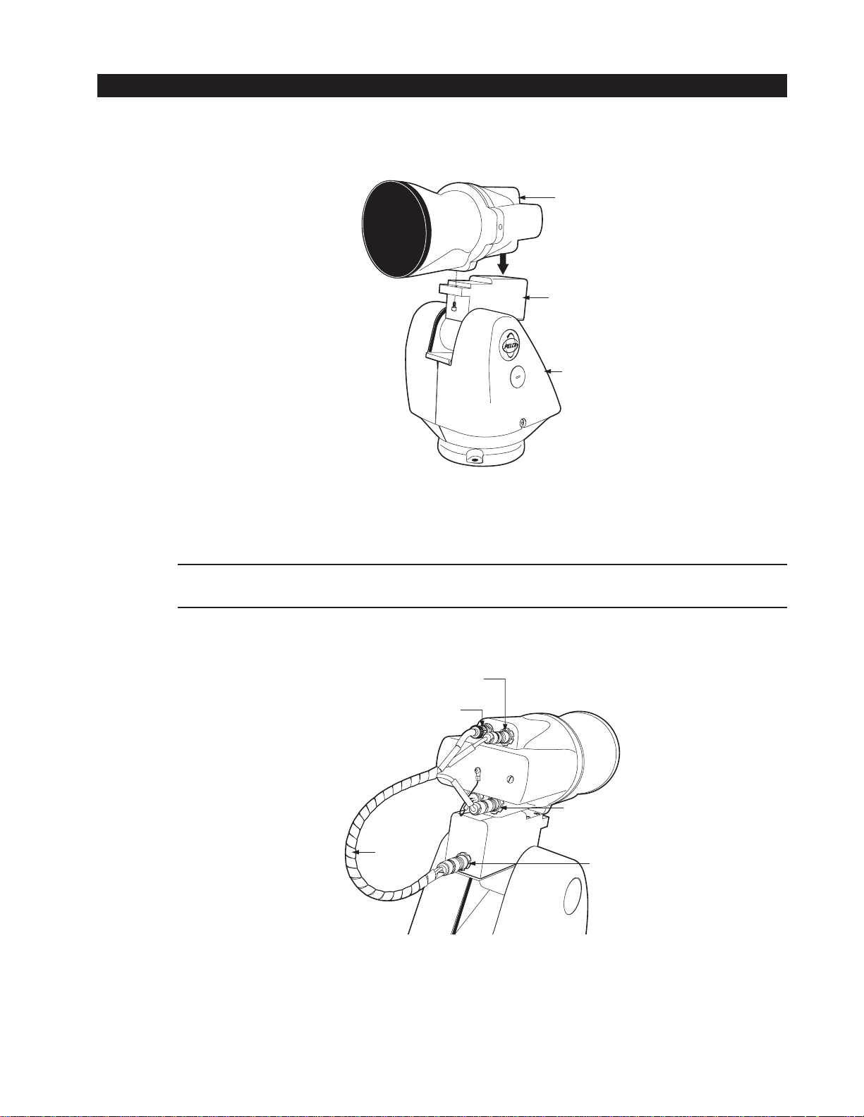
1. Refer to Figure 1 and attach the POD 100 to the tilt table of the Esprit with the 1/4-20 x .50-inch screw (supplied).
Figure 1. POD 100 Attachment to the Tilt Table
2. Refer to Figure 2 and attach the harness cable to the system.
NOTE: The tilt table, power, and communication pin connectors are marked with red alignment dots. To install a pin connector align the
red dot of the female connector with the red dot of the male connector and then lightly push the connector until it locks in place.
7-PIN COMMUNICATIONS
CONNECTOR
BNC VIDEO CONNECTOR
4-PIN POWER
CONNECTOR
CABLE
HARNESS
ESPRIT
TILT TABLE
CONNECTOR
Figure 2. Cable Connections
C312M-A (12/02) 5
Page 6
PAN AND TILT
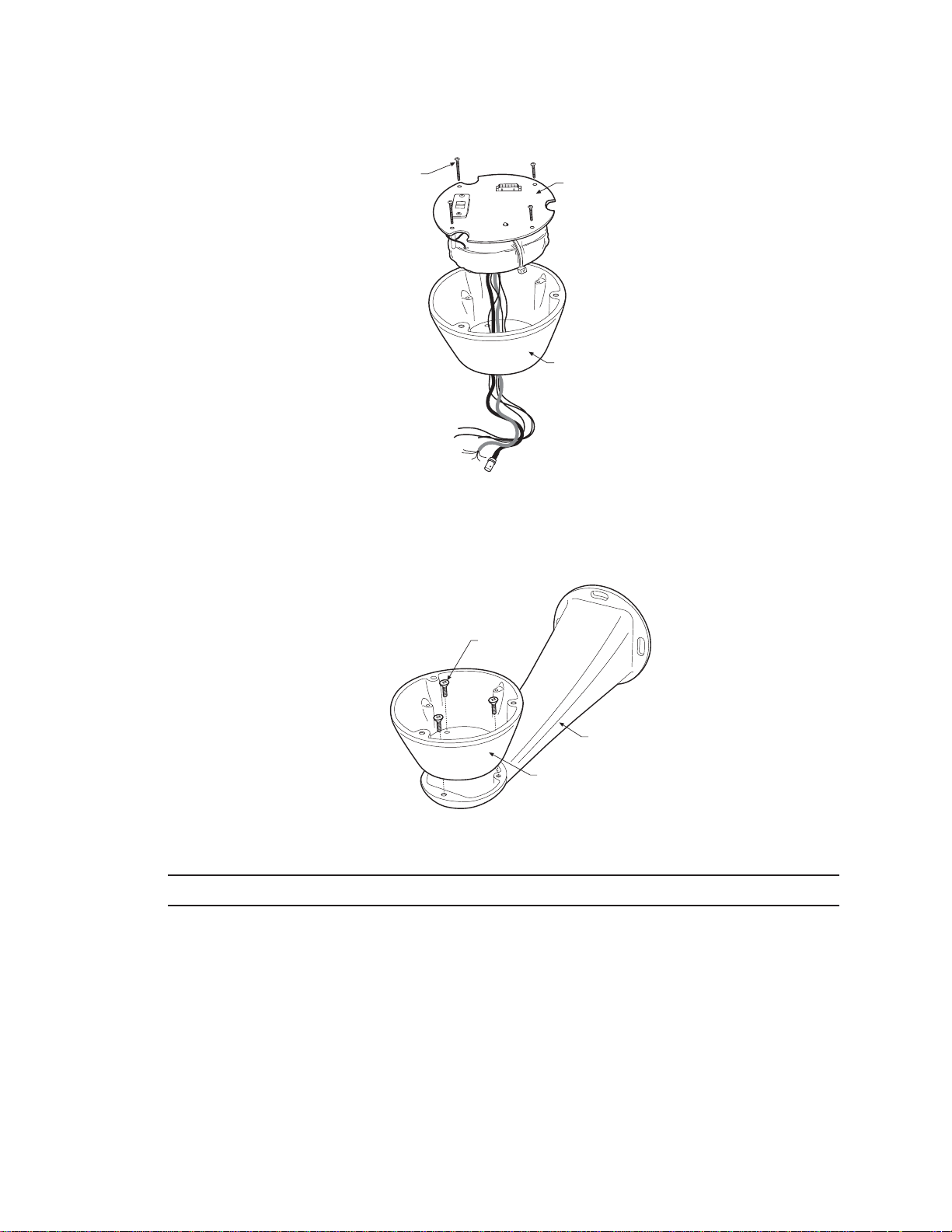
1. Remove the transformer module from the base of the system by loosening the four Phillips screws and lifting the module.
LOOSEN
PHILLIPS
SCREWS
TRANSFORMER
MODULE
BASE
Figure 3. Transformer Removal
2. Attach the base of the system to an Esprit mount (EWM or EPP) with the three flathead 10-32 x 1/2-inch screws and washers
(supplied).
MOUNTING
SCREWS
MOUNT
BASE
01475
Figure 4. Base Installation on Mount
NOTE: The illustration shows the ES30-ISAP Pan and Tilt System mounted to an EWM wall mount.
6 C312M-A (12/02)
Page 7
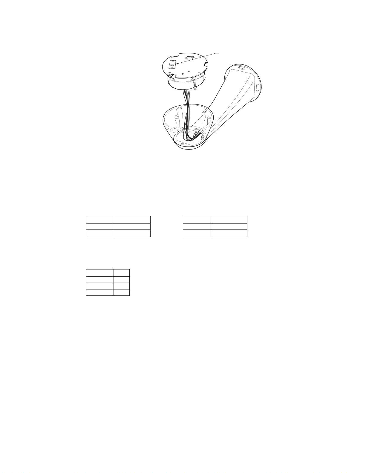
3. Route the wires and cables from the transformer module through the center of the Esprit mount. Reinstall the transformer module
into the base. The transformer module can be positioned in the mount base in only one orientation.
120/230 VOLTAGE
SELECTOR SWITCH
Figure 5. Transformer Reinstallation
4. ES30-ISAP-5 Model Only – Set the 120/230 voltage selector switch on the transformer to the appropriate voltage.
5. Connect wires and cables.
a. Connect to power.
120/230 VAC
Black wire Input (AC Line)
White wire AC Neutral
Green wire Ground
White wire Input (AC Line)
White wire AC Neutral
Green wire Ground
24 VAC
b. Connect the video coaxial cable to the BNC connector.
c. Connect the wiring for a two-wire or four-wire control system. This step does not apply to Coaxitron® control systems.
Green wire RXRed wire RX+
Black wire TXWhite wire TX+
6. Install mount; refer to the installation manual supplied with the mount for instructions.
7. Turn on the power. If the red LED lights, turn off the power and proceed to the next step.
C312M-A (12/02) 7
Page 8
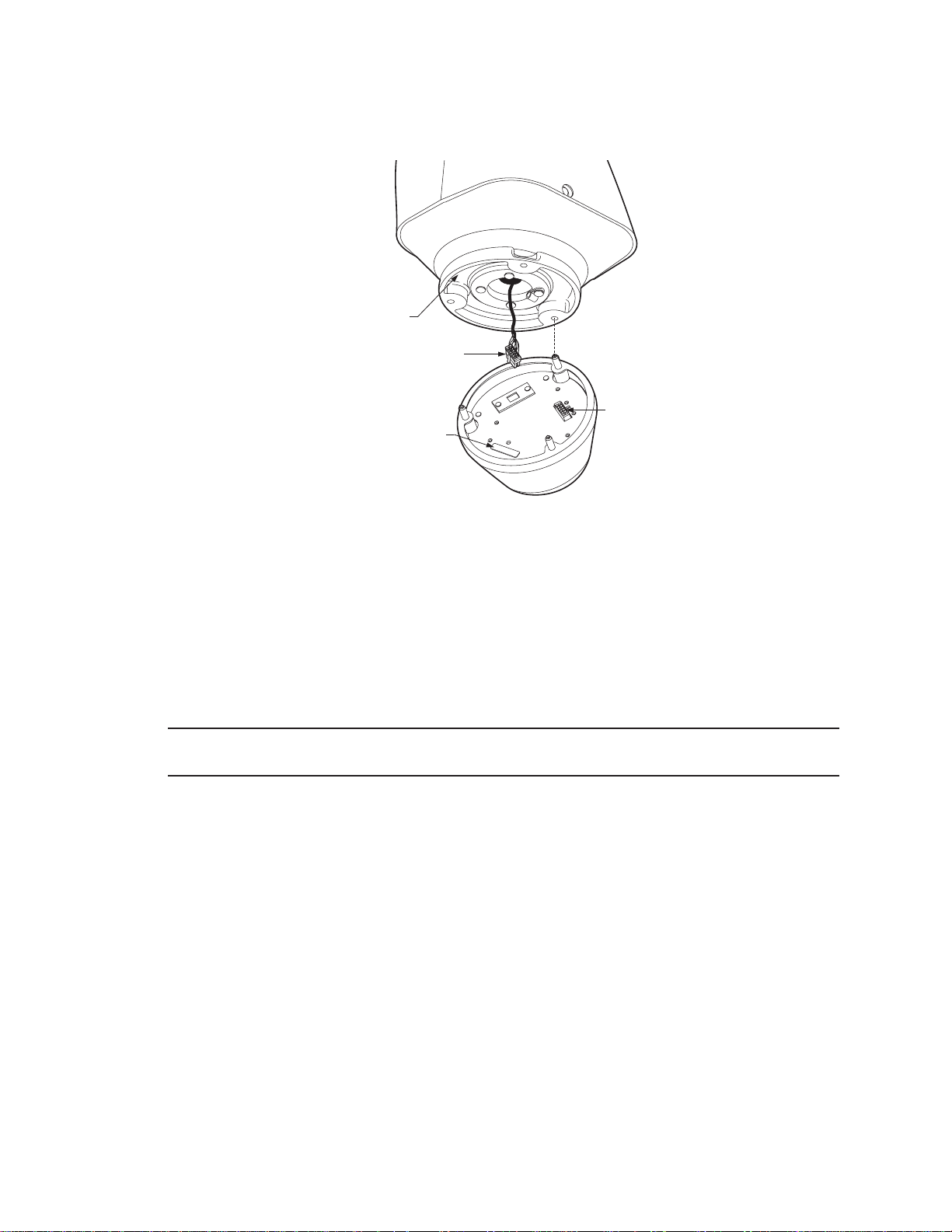
8. Plug the male Esprit system connector, located on the bottom of the pan and tilt, into the female Esprit system connector located on
the transformer module. Align the pan and tilt part number with the alignment label on the base, and then attach the pan and tilt to
the base with three 1/4-20 nuts and washers (supplied).
PART
NUMBER
MALE SYSTEM
CONNECTOR
FEMALE
SYSTEM
ALIGNMENT
LABEL
CONNECTOR
Figure 6. Pan and Tilt Installation
9. Set the receiver address and system baud rate by configuring DIP switches SW1 and SW2.
To set the DIP switches:
a. Remove the plug from the left cover of the pan and tilt. It is not necessary to remove the pan and tilt cover.
b. Set the baud rate (SW1) and receiver address (SW2). For switch settings refer to Tables A and B in the
Appendix
.
c. Replace the plug.
NOTE: Switch settings have no effect on Coaxitron control signals. The Esprit will sense and automatically select input from Coaxitron
control signals in either standard or extended mode.
8 C312M-A (12/02)
Page 9
TXB SERIES TRANSLATOR BOARD INSTALLATION (OPTIONAL)
Pelco’s TXB Series allows controllers from other companies to communicate with the Esprit system.
To install a TXB Series board, remove the left cover of the pan and tilt. Once the cover is removed, refer to the manual supplied with the
translator board to complete the installation.
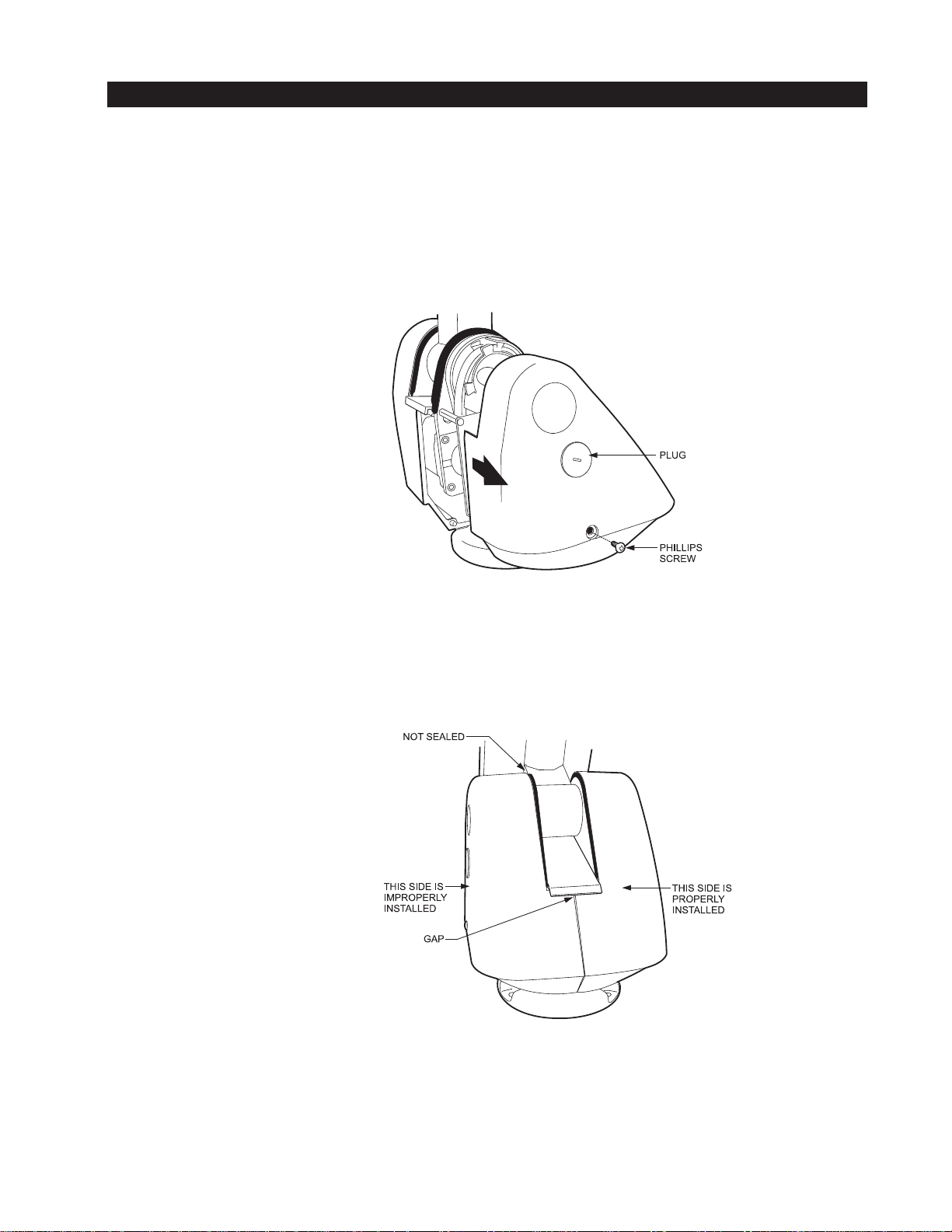
HOW TO REMOVE THE PAN AND TILT COVER
1. Unscrew the Phillips head screw located on the left cover of the pan and tilt.
2. Remove cover and place to the side.
Figure 7. Pan and Tilt Cover Removal
HOW TO REINSTALL THE PAN AND TILT COVER
The pan and tilt covers must be seated properly and have a tight seal all the way around when installed.
Figure 8. Pan and Tilt Cover Seating
C312M-A (12/02) 9
Page 10
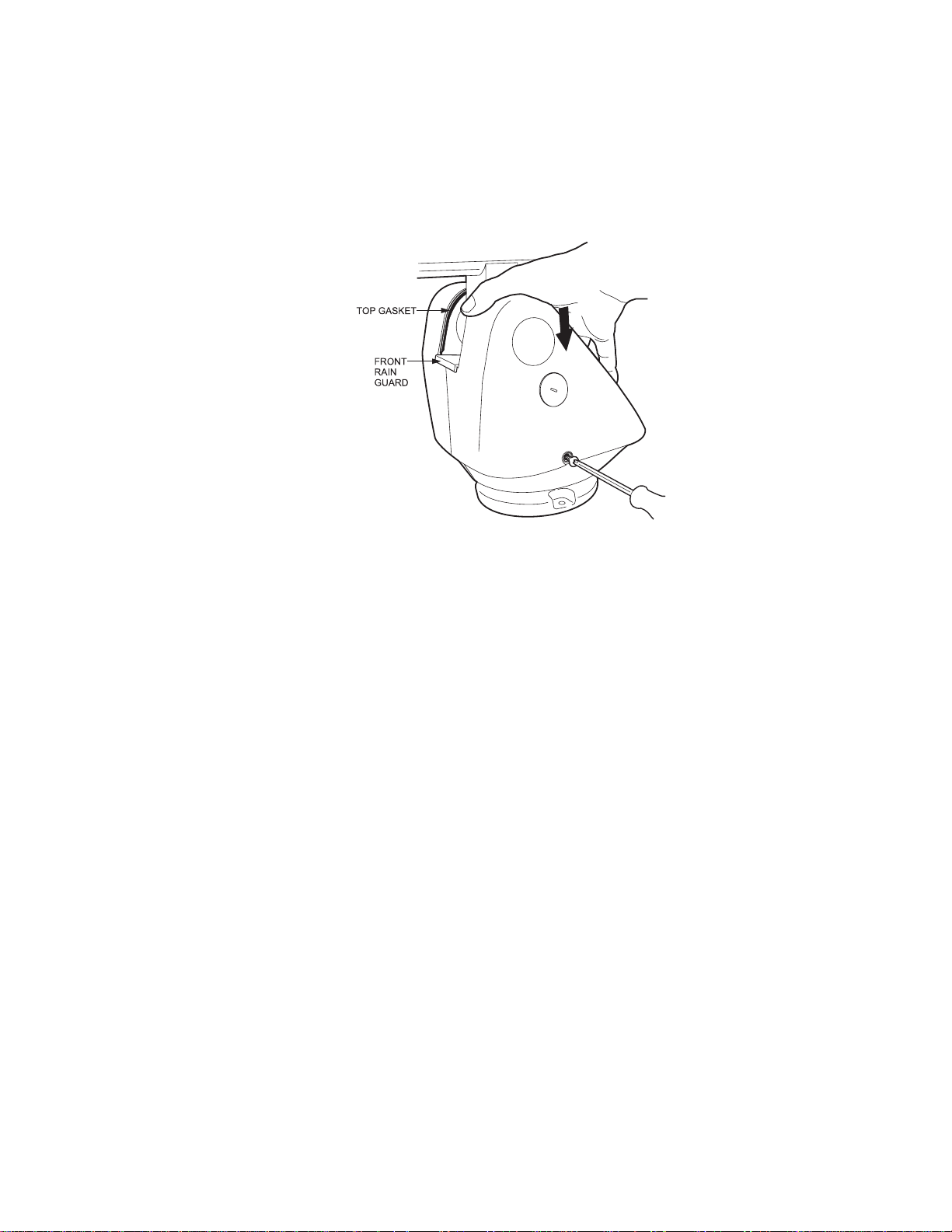
To reinstall the pan and tilt cover, do the following:
1. Properly position the cover and slide it into place. The sides of the cover must fit under the front and back rain guards of the pan and
tilt, and the top of the cover must seat against the lip of the top gasket.
2. Apply pressure and push the top of the cover down to align the fastener holes.
3. Insert the Phillips head screw and tighten. Tighten until the screw will not turn.
Figure 9. Pan and Tilt Cover Reinstallation
10 C312M-A (12/02)
Page 11

OPERATION
POWER-UP DISPLAY
When the Esprit system is powered up or reset, the selected protocol, revision number, and other information is displayed on the monitor.
The information remains on the monitor until the system is moved.
PAN AND TILT OPERATION
Operation How to Control
Pan and Tilt Move joystick left/right and up/down.
Scanning
Stop Scan Call preset 96.
Random Scan Call preset 97.
Frame Scan Call preset 98.
Auto Scan Call preset 99.
Presets Refer to the documentation supplied with the controller.
Patterns Refer to the documentation supplied with the controller.
Zones Refer to the Programming section and to the
documentation supplied with the controller.
For more information refer to
CAMERA OPERATION (POD 100 THERMAL IMAGER)
Operating Notes
.
For detailed information on camera operation, refer to the manual supplied with the POD 100 thermal imager or contact Industrial Security
Alliance Partners, Inc. at (619) 232-7041.
Menu Item Setting ISAP Function
Polarity WHT HOT (default) Sets polarity so that normal white indicates hot.
Polarity BLK HOT Sets polarity so that inverted black indicates hot.
Auto Cal Auto (default) Turns on auto calibration.
Auto Cal Off Turns off auto calibration.
Man Cal Forces a 1-point calibration.
Reset Camera Resets Polarity, Auto Cal, AGC Mode, ROI, and Color Bar to their default settings.
AGC Mode Auto (default) Sets AGC Mode to On. (IRIS OPEN and IRIS CLOSE will override AGC Mode until
the unit is panned or tilted approximately 15 degrees.)
AGC Mode Off Turns AGC Off.
Gain Numeric value Sets the gain value for the ISAP camera; AGC mode is turned Off. (After setting a
value, the value will be updated with the closest threshold setting that changes
the video image.)
Offset Numeric value Sets the offset value for the ISAP camera; AGC mode is turned Off.
ROI (Region of Interest) All (default) Sets ROI to full screen.
ROI (Region of Interest) 3/4 Sets ROI to the center 3/4 of the screen.
ROI (Region of Interest) 1/2 Sets ROI to the center 1/2 of the screen.
ROI (Region of Interest) Center Sets ROI to the center 1/4 of the screen.
Color Bar On Turns on color bars.
Color Bar Off (default) Turns off color bars.
Cam Ver Displays Camera Version numbers.
C312M-A (12/02) 11
Page 12

OPERATING NOTES
ENVIRONMENTAL RANGE
The operating temperature ranges from a minimum of -40°F (-40°C) to a maximum of 122°F (50°C) for sustained system operation or
140°F (60°C) absolute maximum.
PAN AND TILT FUNCTIONS
Controller Pan Tilt
Type (Capability, 360° Continuous (Viewing Range, +33° to -83°)***
Pan Rotation)**
Fixed speed Speed determined by controller Speed determined by controller
Variable speed* 0.5 to 40° per second, 0.5 to 20° per second, depending
depending on joystick position on joystick position
Turbo Mode* 100° per second Does not affect the tilt speed
Preset Mode* 100° per second 30° per second
*50 mph wind speed profile.
**If manual limit stops are set, “Pan Limit” appears on your monitor when a limit stop is reached. This does not apply to scan limit stops.
***When the system reaches the upper limit, “Tilt Limit” appears on your monitor.
PAN, SCAN, AND TILT SPEEDS
Pan and scan speeds are adjustable from 3 to 40 degrees per second through the programming menu. The tilt speed is one-half of the pan
speed.
NOTE: If a preset is set when the system is at the upper tilt limit, the preset label will be overridden by the label “Tilt Limit.” The preset
labels feature will not function.
LENS FUNCTIONS
Focus and iris functions are operated from the controller.
PRESET FUNCTIONS
The Esprit system is capable of going to 64 preset locations, each with a 20-character label. The presets are numbered 1-32 and 35-66.
Refer to the documentation for your control system for programming presets.
If you command the pan and tilt to go to an undefined preset, erratic operation may result.
Presets 33 and 34 are fixed commands, meaning that you cannot program them. Preset 33 is the “flip” command, which pans the system
180 degrees. Preset 34 is the “pan zero” command, which pans the system to the factory-determined zero reference point.
12 C312M-A (12/02)
Page 13

RANDOM, FRAME, AND AUTO SCANNING
Select preset 97 (30) to start random scanning. Select preset 98 (31) to activate frame scanning (three seconds of scanning followed by a
three-second pause). Select preset 99 (32) to start auto (continuous) scanning. Scan limit stops are controlled by software. Refer to the
Limit Stops
When the system reaches a scan limit stop, it reverses direction. Select preset 96 (29) to stop a scan. Any pan and tilt or lens command
also will stop a scan.
NOTE: For AMERICAN DYNAMICS controllers with only 32 presets, set switch SW1-5 on the PCB in the ON position. When SW1-5 is ON,
preset 99 becomes 32
section to program the scan limit stops.
98 becomes 31
97 becomes 30
96 becomes 29
95 becomes 28
93 becomes 26
92 becomes 25
91 becomes 24
90 becomes 23
If the limit stops are turned off (refer to the
Limit Stops
section), presets 23-26 can be used as regular presets.
ZONES
A zone is a programmed pan area with set boundaries and identifying label. The Esprit system has a maximum of eight zones, each with a
20-character label. Zones can be programmed to blank video when the camera pans into the zone area. If zone labels are turned off, the
system displays the message, VIDEO BLANK, to indicate the video is blanked and not failing. (Refer to the
instructions.)
Zone Blank
section for
PATTERNS
The Esprit system can do either one full pattern (1.5, 3, or 6 minutes long) or two half patterns (.75, 1.5, or 3 minutes long). This pattern
can consist of any standard pan and tilt command. Presets, flip, and turbo are not allowed in a pattern. Zones can be enabled while
running a pattern. Refer to the documentation for your control system to program and run patterns.
PARK
If the Esprit system does not receive any commands for a specified period of time (refer to the
go to preset 1 and park. If the time specified is zero, or if preset 1 has not been programmed, the system will not park.
Park Time Minutes
section), the system will
C312M-A (12/02) 13
Page 14

QUICK START GUIDE – SYSTEM SETUP
PROGRAMMING GUIDE – ES30-ISAP PAN AND AND TILT SYSTEM
1. Access main menu (preset 95).
2. Make main menu selections.
Joystick: Move up or down to position cursor or to toggle between selections.
Iris Open: Enter.
Iris Close: Cancel.
Gain/AGC Menu
AGC mode
Gain
Camera Menu
Polarity
Auto Cal
Man Cal
Reset Camera
<GAIN/AGC>
Next
Exit
Line Sync Menu
Line sync
Line sync phase
Exit
Offset
Exit
Next Menu
ROI
Color Bar
Cam Ver
Prev
Exit
PRESETS
The following presets are reserved for
special functions:
Preset Function
1Park
33 Flip command
34 Pan zero command
89 Toggle Polarity
90-91 Manual Limit stops
92-93 Auto Limit stops
95 Access Main Menu
96 Stop a scan
97 Random Scanning
98 Frame Scanning
99 Start Auto Scanning
MAIN MENU
<Camera>*
<Line Sync>
<Power Up Mode>
<Limit Stop>
<Other>
EXIT
*For information on camera
operation, refer to the
manual supplied with the
POD 100 thermal imager or
contact Industrial Security
Alliance Partners, Inc. at
(619) 232-7041.
14 C312M-A (12/02)
Power Up Menu
Power Up
Exit
Limit Stop Menu
Limit Stops
Set Man Limits
Clear Man Limits
Set Scan Limits
Clear Scan Limits
Exit
Other Menu
Proportional pan
Park time minutes
Scan speed deg/s
Pattern length
Spd Profile
<Zone Blank>
Exit
Zone Blank Menu
Video Blank Zone 1
2
3
4
5
6
7
8
Exit
NOTE: For AMERICAN DYNAMICS
controllers with only 32 presets, set
switch SW1-5 on the PCB in the ON
position. When SW1-5 is ON,
preset 99 becomes 32
98 becomes 31
97 becomes 30
96 becomes 29
95 becomes 28
93 becomes 26
92 becomes 25
91 becomes 24
90 becomes 23
If the limit stops are turned off (refer to
Limit Stops
the
can be used as regular presets.
NOTE: In the operation and programming instructions, sometimes
a number in parentheses follows a
preset. This second number is for
32-preset mode.
section), presets 23-26
Page 15

HOW TO ACCESS THE MAIN MENU (PRESET 95)
You can call up the main menu on your monitor by programming (setting or creating) preset 95 (preset 28 if in AD32-preset mode).
Programming preset 95 for Pelco’s controllers varies according to the type of controller you are using. Instructions for programming
preset 95 are given below for various Pelco controllers.
CM6700/CM6800
1. Enter the number of the Esprit system and press the CAM key.
2. Enter 95 and hold the PRESET key for two seconds.
3. In the Edit Preset menu, arrow to SET and press the ACK key. The main menu appears.
KBD200A/KBD300A (DIRECT MODE ONLY)
1. Enter 95.
2. Hold the PRESET key (approximately two seconds) until the main menu appears on the screen.
CM9500
1. Enter the number of the Esprit system and press the CAM key. The Main menu appears.
2. Highlight SETUP in the Main menu and press the SELECT key.
3. Highlight CAM in the Setup menu and press the SELECT key.
4. Highlight PRESET in the Camera menu and press the SELECT key.
5. Enter 95 and press the F1 key. The main menu appears.
CM9740/CM9760
1. Press the ESCAPE key to open the Main menu. Select DEF. The Define Submenu appears.
2. Enter your four-digit PIN if this is your first time entering this mode.
3. Enter 95 and select PRST. The main menu appears on the monitor.
4. Select the Quit icon to return to the default menu.
KBD4000/KBD4002 (GENEX® MULTIPLEXER)
1. Press the SPOT MONITOR key.
2. Enter 95, then hold the PRESET key (approximately two seconds) until the main menu appears on the screen.
MPT9500
Standard Coaxitron Mode
1. Enter 95 and press the PRESET SET key.
2. Position the asterisk in the YES row and press the F1 key. The main menu appears.
EXTENDED COAXITRON OR RS-485 MODE
1. Enter 95 and press the PRESET SET key.
2. Press the F2 key. The main menu appears.
PELCONET
1. Check the Set box.
2. Click the preset 95 button. The main menu appears.
™
C312M-A (12/02) 15
Page 16

CAMERA
Main Menu
<Camera>
<Line Sync>
<Power Up Mode>
<Limit Stop>
<Other>
EXIT
For information on camera operation, refer to the manual supplied with the POD 100 thermal imager or contact Industrial Security
Alliance Partners, Inc. at (619) 232-7041.
➞
Camera Menu
Polarity
Auto Cal
Man Cal
Reset Camera
<GAIN/AGC>
Next
Exit
16 C312M-A (12/02)
Page 17

LIMIT STOPS
Main Menu
<Camera>
<Line Sync>
<Power Up Mode>
<Limit Stop>
<Other>
EXIT
➞
Limit Stop Menu
Limit Stops Off
Set Man Limits
Clear Man Limits
Set Scan Limits
Clear Scan Limits
Exit
TURNING LIMIT STOPS ON OR OFF
To change the limit stop mode:
1. Program preset 95 (28). The main menu appears.
2. Position the cursor (>) beside Limit Stop.
3. Press the Iris Open button to enter the Limit Stop menu.
4. Position the cursor (>) beside Limit Stops.
5. Press the Iris Open button. The cursor moves to the right, beside the word On or Off.
6. Move the joystick up or down to toggle between On and Off.
7. SELECT – Press the Iris Open button on your keyboard to select your choice.
CANCEL – Press the Iris Close button if you do not want to change the setting.
PROGRAMMING LIMIT STOPS
Manual Limit Stops
When manual limit stops are set, a (joystick/pan and tilt keys) pan operation stops when a limit stop is reached. The manual limit stops
can be set in one of two ways:
At the controller by programming presets 90 (23) and 91 (24)
or
At the controller by programming the Limit Stop menu
Presets
Refer to the documentation for your control system for programming presets, then do the following:
1. Make sure limit stops are turned ON, and then exit the menu.
2. Push the joystick left until you reach the limit you want the camera to go to on the left.
3. Program preset 90 (23).
4. Push the joystick right to the limit you want the camera to go to on the right.
5. Program preset 91 (24).
Setting presets 90 (23) and 91 (24) to the same point disables manual limit stops.
Limit Stops Menu
The manual pan limit stops can be set at the controller using the Limit Stop menu:
1. Program preset 95 (28). The main menu appears.
2. Position the cursor (>) beside Limit Stop.
3. Press the Iris Open button to enter the Limit Stop menu.
4. Move the cursor to Set Man Limits, and press the Iris Open button. PRESS IRIS OPEN TO SET LEFT LIMIT appears.
5. Move the pan and tilt to the desired left limit position, and press the Iris Open button to set the left manual limit. PRESS IRIS OPEN
TO SET RIGHT LIMIT appears.
6. Move the pan and tilt to the desired right limit position, and press the Iris Open button to set the right manual limit.
7. Exit the Limit Stop menu.
C312M-A (12/02) 17
Page 18

Clear Manual Stops
To clear the manual limit stops:
1. Program preset 95 (28). The main menu appears.
2. Position the cursor (>) beside Limit Stop.
3. Press the Iris Open button to enter the Limit Stop menu.
4. Move the cursor to Clear Man Limits, and press the Iris Open button. The cursor will flash to an asterisk (*) briefly to indicate the
limits have been disabled.
SCAN LIMIT STOPS
When scan limit stops are set, the pan and tilt reverses direction during random, frame, or auto scanning when a limit stop is reached.
The manual scan limit stops can be set in one of two ways:
At the controller by programming presets 92 and 93
or
At the controller by programming the Limit Stop menu:
Presets
Refer to the documentation for your control system for programming presets, then do the following:
1. Make sure limit stops are turned ON, and then exit the menu.
2. Push the joystick left until you reach the limit you want the camera to go to on the left.
3. Program preset 92 (25).
4. Push the joystick right to the limit you want the camera to go to on the right.
5. Program preset 93 (26).
Setting presets 92 (25) and 93 (26) to the same point disables manual limit stops.
NOTE: Programming preset 92 (25) disables the scan limit stops until preset 93 (26) is set. Preset 92 is the left scan limit and preset 93 is the
right scan limit.
Limit Stops Menu
The manual pan limit stops can be set at the controller using the Limit Stop menu:
1. Program preset 95 (28). The main menu appears.
2. Position the cursor (>) beside Limit Stop.
3. Press the Iris Open button to enter the Limit Stop menu.
4. Move the cursor to Set Scan Limits, and press the Iris Open button. PRESS IRIS OPEN TO SET LEFT LIMIT appears.
5. Move the pan and tilt to the desired left limit position, and press the Iris Open button to set the left manual limit. PRESS IRIS OPEN
TO SET RIGHT LIMIT appears.
6. Move the pan and tilt to the desired right limit position, and press the Iris Open button to set the right scan limit.
7. Exit the Limit Stop menu.
Clear Scan Limit Stops
To clear the scan limit stops, move the cursor to Clear Scan Limits and press the Iris Open button. The cursor will flash to an asterisk (*)
briefly to indicate the limits have been disabled.
18 C312M-A (12/02)
Page 19

LINE SYNCHRONIZATION
Main Menu
<Camera>
<Line Sync>
<Power Up Mode>
<Limit Stop>
<Other>
EXIT
If cameras are out of phase with each other, they may produce what appears to be vertical roll when switching between cameras.
There are two settings for line synchronization:
ON – Adjust the synchronization of the power line voltage so that it is in phase with other cameras.
OFF – The system synchronizes to an internal clock.
To change the line synchronization settings:
1. Program preset 95 (28). The main menu appears.
2. Position the cursor (>) beside Line Sync.
3. Press the Iris Open button. The Line Sync menu appears.
4. Position the cursor (>) beside one of the choices. Press the Iris Open button.
LINE SYNC – The cursor moves to one of two choices: ON or OFF. Move the joystick up or down to toggle between them. Press the Iris
Open button to select the choice. If you changed to OFF, the camera may reset itself as it adjusts to the new synchronization. If the camera
resets, it will only affect the line synchronization. It will not change any other camera parameters, such as auto focus or auto iris. Press
the Iris Close button if you do not want to change the setting.
➞
Line Sync Menu
Line sync On
Line sync phase 0
Exit
LINE SYNC PHASE – The cursor moves to a numeric value. Move the joystick up or down to change the value. The value represents the
phase angle in tenths of a degree between 0 and 359 degrees. For example, 900 is 90 degrees, 1200 is 120 degrees, and 2400 is
240 degrees. Press the Iris Open button on your keyboard to select your choice. The Line Sync setting changes to ON. The camera may
reset or the picture on your monitor may wiggle when you change the phase angle. If the camera resets, it will only affect the line
synchronization. It will not change any other camera parameters, such as auto focus or auto iris. Press the Iris Close button if you do not
want to change the setting.
C312M-A (12/02) 19
Page 20

PARK TIME MINUTES
Main Menu Other Menu
<Camera>
<Line Sync>
<Power Up Mode>
<Limit Stop>
<Other>
EXIT
This feature causes the system to park at preset 1 after a programmed number of minutes of control inactivity. The time can be set from 1
minute to 720 minutes (12 hours), or it can be set to zero, which disables this feature.
To change the park time:
1. Program preset 95 (28). The main menu appears.
2. Position the cursor (>) beside Other.
3. Press the Iris Open button to enter the Other menu.
4. Position the cursor (>) beside Park Time Minutes.
5. Press the Iris Open button. The cursor moves to the right, beside the current park time.
6. Move the joystick up or down to change the park time.
7. SELECT – Press the Iris Open button on your keyboard to select your choice.
CANCEL – Press the Iris Close button if you do not want to change the setting.
NOTE: Preset 1 must be programmed for the system to park.
➞
Proportional pan On
Park time minutes 0
Scan speed deg/s 25
Pattern length 1.5 min
Spd Profile
<Zone Blank>
Exit
90 MPH wind
PATTERN LENGTH
Main Menu
<Camera>
<Line Sync>
<Power Up Mode>
<Limit Stop>
<Other>
EXIT
The ESPRIT can do the following:
One full pattern – 1.5, 3, or 6 minutes long
or
Two half patterns – .75, 1.5, or 3 minutes long
This pattern can consist of any standard pan and tilt command. Presets, flip, and turbo are not allowed in a pattern. Zone scan can be
enabled while running a pattern.
To set the pattern length:
1. Program preset 95 (28). The main menu appears.
2. Position the cursor (>) beside Other.
3. Press the Iris Open button to enter the menu entitled Other.
4. Position the cursor (>) beside Pattern Length.
5. Press the Iris Open button. The cursor moves to the right, beside the number of minutes (1.5, 3, or 6).
6. Move the joystick up or down to toggle through the number of minutes (1.5, 3, or 6).
7. SELECT – Press the Iris Open button on your keyboard to select your choice.
CANCEL – Press the Iris Close button if you do not want to change the setting.
➞
Other Menu
Proportional pan On
Park time minutes 0
Scan speed deg/s 25
Pattern length 1.5 min
Spd Profile
<Zone Blank>
Exit
90 MPH wind
CAUTION: If the length is changed, all patterns that were stored are erased.
20 C312M-A (12/02)
Page 21

POWER-UP MODE
Main Menu
<Camera>
<Line Sync>
<Power Up Mode>
<Limit Stop>
<Other>
EXIT
This feature lets the system resume a desired condition following power-up. The menu includes the following choices.
• Default – On power-up, the system goes through a configuration cycle and stops at zero reference, showing “Configuration
Done,” address, and mode settings on the screen.
• Park – The system moves to preset 1 when the power-up sequence finishes. The only text on the screen is the preset label (if
any is programmed).
• Scan Auto – The system initiates scan mode when the power-up sequence finishes. Again, there is no text.
• Scan Frame – The system initiates a frame scan when the power-up sequence finishes.
• Scan Rand – The system initiates a random scan when the power-up sequence finishes.
• Full Pat – The system initiates its programmed pattern when the power-up sequence finishes. The length can be set to 1.5, 3,
or 6 minutes.
➞
Power Up Menu
Power Up Default
Exit
• Half Pat 1 – The system initiates the first half-pattern when the power-up sequence finishes. The length can be set to .75, 1.5,
or 3 minutes.
• Half Pat 2 – The system initiates the second half-pattern when the power-up sequence finishes. The length can be set to .75,
1.5, or 3 minutes.
The default setting is Default.
To select the power-up mode:
1. Program preset 95 (28). The main menu appears.
2. Position the cursor (>) beside Power Up.
3. Press the Iris Open button to enter the Power Up menu.
4. Press the Iris Open button to move the cursor to the right.
5. Move the joystick up or down to cycle through the selections. Stop on the item you want to select.
6. SELECT – Press the Iris Open button on your keyboard to select your choice.
CANCEL – Press the Iris Close button if you do not want to change the setting.
C312M-A (12/02) 21
Page 22

PROPORTIONAL PAN
Main Menu
<Camera>
<Line Sync>
<Power Up Mode>
<Limit Stop>
<Other>
EXIT
Proportional pan does not function with this version of Esprit.
➞
Other Menu
Proportional pan On
Park time minutes 0
Scan speed deg/s 25
Pattern length 1.5 min
Spd Profile
<Zone Blank>
Exit
90 MPH wind
22 C312M-A (12/02)
Page 23

SCAN SPEED
Main Menu
<Camera>
<Line Sync>
<Power Up Mode>
<Limit Stop>
<Other>
EXIT
The scan speed is adjustable from 1-40 degrees per second. This occurs in three scan modes: auto, random, and frame scan.
To change the scan speed:
1. Program preset 95 (28). The main menu appears.
2. Position the cursor (>) beside Other.
3. Press the Iris Open button to enter the menu entitled Other.
4. Position the cursor (>) beside Scan Speed deg/s.
5. Press the Iris Open button. The cursor moves to the right, beside the number of degrees.
6. Move the joystick up or down to toggle through the number of degrees (1-40) until you reach the number you want. (If set on a low
number, the scan will appear to barely move but is still functioning.)
7. SELECT – Press the Iris Open button on your keyboard to select your choice.
CANCEL – Press the Iris Close button if you do not want to change the setting.
➞
Other Menu
Proportional pan On
Park time minutes 0
Scan speed deg/s 25
Pattern length 1.5 min
Spd Profile
<Zone Blank>
Exit
90 MPH wind
SPEED PROFILE
Main Menu
<Camera>
<Line Sync>
<Power Up Mode>
<Limit Stop>
<Other>
EXIT
This feature allows the operator to set the wind speed conditions for the location of the Esprit system. You can set two wind speed
profiles of 50 mph or 90 mph in which the system will remain operational. In both settings, the pan speed will be a maximum of 40
degrees per second. The difference will be in the turbo and preset pan speeds. The turbo and preset pan speeds are 100 degrees per
second in the 50 mph wind profile setting and 50 degrees per second in the 90 mph profile.
To set the speed profile:
1. Program preset 95 (28). The main menu appears.
2. Position the cursor (>) beside Other.
3. Press the Iris Open button to enter the menu entitled Other.
4. Position the cursor (>) beside Spd Profile.
5. Press the Iris Open button. The cursor moves to the right, beside the wind speed (50 mph wind or 90 mph wind).
6. Move the joystick up or down to toggle between the wind speeds (50 mph wind or 90 mph wind).
7. SELECT – Press the Iris Open button on your keyboard to select your choice.
CANCEL – Press the Iris Close button if you do not want to change the setting.
➞
Other Menu
Proportional pan On
Park time minutes 0
Scan speed deg/s 25
Pattern length 1.5 min
Spd Profile
<Zone Blank>
Exit
90 MPH wind
C312M-A (12/02) 23
Page 24

ZONES
Basic rules for setting zones:
1. Refer to the documentation for your control system to program zones.
2. Establish zones using the controller, prior to programming ZONE BLANK with the
Esprit on-screen menu.
3. To accurately set zone areas, zoom wide to the maximum field of view.
4. Set zones moving the joystick left to right. The left position is always the start position.
ZONE BLANK
Main Menu
<Camera>
<Line Sync>
<Power Up Mode>
<Limit Stop>
<Other>
EXIT
The Esprit system features on-screen programmable zone blanking. This feature lets you define any zone as blanked for video
(viewing/recording).
Zones can be programmed to overlap each other, although this is not recommended. If you program two zones to overlap, the title of
the zone with the highest priority (zone 8 is the highest, zone 1 is the lowest) will be displayed on the monitor. This rule also applies
to blanked zones that overlap. The blanking status of the zone with the highest priority will determine if the area is blanked or not.
Example: Zone 1 is blanked but a portion of the zone overlaps zone 8 which is not blanked. The overlapped portion of zone 1 will be
displayed on the monitor with the zone 8 label.
There are two video zone blank settings:
On – Enables video blanking.
Off – Disables video blanking.
To change the video blank zone setting:
1. Program preset 95 (28). The main menu appears.
2. Position the cursor (>) beside Other.
3. Press the Iris Open button to enter the Other menu.
4. Position the cursor (>) beside Zone Blank.
5. Press the Iris Open button to enter the Zone Blank menu.
6. Position the cursor (>) beside the number of the zone for which you want to set the blank option.
7. Press the Iris Open button. The cursor moves to the right, beside the word On or Off.
8. Move the joystick up or down to toggle between the words On and Off.
9. SELECT – Press the Iris Open button on your keyboard to select your choice.
CANCEL – Press the Iris Close button if you do not want to change the setting.
➞
Other Menu
Proportional pan On
Park time minutes 0
Scan speed deg/s 25
Pattern length 1.5 min
Spd Profile
<Zone Blank>
Exit
90 MPH wind
➞
Zone Blank Menu
Video Blank Zone 1
Exit
Off
2
Off
3
Off
4
Off
5
Off
6
Off
7
Off
8
Off
24 C312M-A (12/02)
Page 25

PRODUCT SUPPORT
ES30-ISAP PAN AND TILT SYSTEM CONTACT:
Pelco
3500 Pelco Way
Clovis, CA 93612 USA
Tel: 800/289-9100 (USA & Canada)
1-559/292-1981 (International)
www.pelco.com
POD 100 THERMAL IMAGER (CAMERA) CONTACT:
Industrial Security Alliance Partners, Inc.
1495 Pacifica Highway, Suite 350
San Diego, CA 92101
Tel: 619-232-7041
www. isapusa.com
C312M-A (12/02) 25
Page 26

APPENDIX
NOTE: Esprit will sense and automatically select input from Coaxitron control signals in either the standard or extended mode. Therefore, the DIP switch
settings have no effect on Coaxitron control signals.
Table A. Switch Settings for SW1
Baud Rate Switch Setting
SW1-1 SW1-2 SW1-3
2400 OFF OFF OFF*
4800 ON OFF OFF*
9600 OFF ON OFF*
*SW1-3 is not used; set it in the OFF position.
Switch Setting
SW1-4 SW1-5 SW1-6 SW1-7 SW1-8
OFF* Note (1) Note (2) Note (3) Note (4)
NOTES:
(1) SW1-5 OFF - For controllers that have more than 32 presets.
ON - For American Dynamics controllers (32 presets).
(2) SW1-6 OFF - For all control systems except CM9502 with variable speed keyboards.
For CM9502 with fixed speed keyboards, set switch OFF.
ON - For CM9502 with variable speed keyboards to get smoother joystick control.
(3) SW1-7 OFF - RS-422 transmitter is not terminated.
ON - RS-422 transmitter is terminated.
(4) SW1-8 OFF - RS-422 receiver is not terminated.
ON - RS-422 receiver is terminated.
*SW1-4 is not used; set it in the OFF position.
26 C312M-A (12/02)
Page 27

Table B. Switch Settings for SW2
Receiver Address Switch Setting
P-Type D-Type
Control Control SW2-1 SW2-2 SW2-3 SW2-4 SW2-5 SW2-6 SW2-7 SW2-8
1–OFF OFF OFF OFF OFF OFF OFF OFF
21ONOFF OFF OFF OFF OFF OFF OFF
32OFF ON OFF OFF OFF OFF OFF OFF
43ONON OFF OFF OFF OFF OFF OFF
54OFF OFF ON OFF OFF OFF OFF OFF
65ONOFF ON OFF OFF OFF OFF OFF
76OFF ON ON OFF OFF OFF OFF OFF
87ONON ON OFF OFF OFF OFF OFF
98OFF OFF OFF ON OFF OFF OFF OFF
10 9 ON OFF OFF ON OFF OFF OFF OFF
11 10 OFF ON OFF ON OFF OFF OFF OFF
12 11 ON ON OFF ON OFF OFF OFF OFF
13 12 OFF OFF ON ON OFF OFF OFF OFF
14 13 ON OFF ON ON OFF OFF OFF OFF
15 14 OFF ON ON ON OFF OFF OFF OFF
16 15 ON ON ON ON OFF OFF OFF OFF
17 16 OFF OFF OFF OFF ON OFF OFF OFF
18 17 ON OFF OFF OFF ON OFF OFF OFF
19 18 OFF ON OFF OFF ON OFF OFF OFF
20 19 ON ON OFF OFF ON OFF OFF OFF
21 20 OFF OFF ON OFF ON OFF OFF OFF
22 21 ON OFF ON OFF ON OFF OFF OFF
23 22 OFF ON ON OFF ON OFF OFF OFF
24 23 ON ON ON OFF ON OFF OFF OFF
25 24 OFF OFF OFF ON ON OFF OFF OFF
26 25 ON OFF OFF ON ON OFF OFF OFF
27 26 OFF ON OFF ON ON OFF OFF OFF
28 27 ON ON OFF ON ON OFF OFF OFF
29 28 OFF OFF ON ON ON OFF OFF OFF
30 29 ON OFF ON ON ON OFF OFF OFF
31 30 OFF ON ON ON ON OFF OFF OFF
32 31 ON ON ON ON ON OFF OFF OFF
–32OFF OFF OFF OFF OFF ON OFF OFF
–33ONOFF OFF OFF OFF ON OFF OFF
–34OFF ON OFF OFF OFF ON OFF OFF
–35ONONOFF OFF OFF ON OFF OFF
–36OFF OFF ON OFF OFF ON OFF OFF
–37ONOFF ON OFF OFF ON OFF OFF
–38OFF ON ON OFF OFF ON OFF OFF
–39ONONONOFF OFF ON OFF OFF
–40OFF OFF OFF ON OFF ON OFF OFF
–41ONOFF OFF ON OFF ON OFF OFF
–42OFF ON OFF ON OFF ON OFF OFF
–43ONONOFF ON OFF ON OFF OFF
–44OFF OFF ON ON OFF ON OFF OFF
–45ONOFF ON ON OFF ON OFF OFF
–46OFF ON ON ON OFF ON OFF OFF
–47ONONONONOFF ON OFF OFF
–48OFF OFF OFF OFF ON ON OFF OFF
–49ONOFF OFF OFF ON ON OFF OFF
–50OFF ON OFF OFF ON ON OFF OFF
–51ONONOFF OFF ON ON OFF OFF
–52OFF OFF ON OFF ON ON OFF OFF
–53ONOFF ON OFF ON ON OFF OFF
–54OFF ON ON OFF ON ON OFF OFF
–55ONONONOFF ON ON OFF OFF
Receiver Address Switch Setting
P-Type D-Type
Control Control SW2-1 SW2-2 SW2-3 SW2-4 SW2-5 SW2-6 SW2-7 SW2-8
–56OFF OFF OFF ON ON ON OFF OFF
–57ONOFF OFF ON ON ON OFF OFF
–58OFF ON OFF ON ON ON OFF OFF
–59ONONOFF ON ON ON OFF OFF
–60OFF OFF ON ON ON ON OFF OFF
–61ONOFF ON ON ON ON OFF OFF
–62OFF ON ON ON ON ON OFF OFF
–63ONONONONONONOFFOFF
–64OFF OFF OFF OFF OFF OFF ON OFF
–65ONOFF OFF OFF OFF OFF ON OFF
–66OFF ON OFF OFF OFF OFF ON OFF
–67ONONOFF OFF OFF OFF ON OFF
–68OFF OFF ON OFF OFF OFF ON OFF
–69ONOFF ON OFF OFF OFF ON OFF
–70OFF ON ON OFF OFF OFF ON OFF
–71ONONONOFF OFF OFF ON OFF
–72OFF OFF OFF ON OFF OFF ON OFF
–73ONOFF OFF ON OFF OFF ON OFF
–74OFF ON OFF ON OFF OFF ON OFF
–75ONONOFF ON OFF OFF ON OFF
–76OFF OFF ON ON OFF OFF ON OFF
–77ONOFF ON ON OFF OFF ON OFF
–78OFF ON ON ON OFF OFF ON OFF
–79ONONONONOFF OFF ON OFF
–80OFF OFF OFF OFF ON OFF ON OFF
–81ONOFF OFF OFF ON OFF ON OFF
–82OFF ON OFF OFF ON OFF ON OFF
–83ONONOFF OFF ON OFF ON OFF
–84OFF OFF ON OFF ON OFF ON OFF
–85ONOFF ON OFF ON OFF ON OFF
–86OFF ON ON OFF ON OFF ON OFF
–87ONONONOFF ON OFF ON OFF
–88OFF OFF OFF ON ON OFF ON OFF
–89ONOFF OFF ON ON OFF ON OFF
–90OFF ON OFF ON ON OFF ON OFF
–91ONONOFF ON ON OFF ON OFF
–92OFF OFF ON ON ON OFF ON OFF
–93ONOFF ON ON ON OFF ON OFF
–94OFF ON ON ON ON OFF ON OFF
–95ONONONONONOFF ON OFF
–96OFF OFF OFF OFF OFF ON ON OFF
–97ONOFF OFF OFF OFF ON ON OFF
–98OFF ON OFF OFF OFF ON ON OFF
–99ONONOFF OFF OFF ON ON OFF
– 100 OFF OFF ON OFF OFF ON ON OFF
– 101 ON OFF ON OFF OFF ON ON OFF
– 102 OFF ON ON OFF OFF ON ON OFF
– 103 ON ON ON OFF OFF ON ON OFF
– 104 OFF OFF OFF ON OFF ON ON OFF
– 105 ON OFF OFF ON OFF ON ON OFF
– 106 OFF ON OFF ON OFF ON ON OFF
– 107 ON ON OFF ON OFF ON ON OFF
– 108 OFF OFF ON ON OFF ON ON OFF
– 109 ON OFF ON ON OFF ON ON OFF
– 110 OFF ON ON ON OFF ON ON OFF
– 111 ON ON ON ON OFF ON ON OFF
(Continued on next page)
C312M-A (12/02) 27
Page 28

Table B. Switch Settings for SW2 (Continued)
Receiver Address Switch Setting
P-Type D-Type
Control Control SW2-1 SW2-2 SW2-3 SW2-4 SW2-5 SW2-6 SW2-7 SW2-8
– 112 OFF OFF OFF OFF ON ON ON OFF
– 113 ON OFF OFF OFF ON ON ON OFF
– 114 OFF ON OFF OFF ON ON ON OFF
– 115 ON ON OFF OFF ON ON ON OFF
– 116 OFF OFF ON OFF ON ON ON OFF
– 117 ON OFF ON OFF ON ON ON OFF
– 118 OFF ON ON OFF ON ON ON OFF
– 119 ON ON ON OFF ON ON ON OFF
– 120 OFF OFF OFF ON ON ON ON OFF
– 121 ON OFF OFF ON ON ON ON OFF
– 122 OFF ON OFF ON ON ON ON OFF
– 123 ON ON OFF ON ON ON ON OFF
– 124 OFF OFF ON ON ON ON ON OFF
– 125 ON OFF ON ON ON ON ON OFF
– 126 OFF ON ON ON ON ON ON OFF
– 127 ON ON ON ON ON ON ON OFF
– 128 OFF OFF OFF OFF OFF OFF OFF ON
– 129 ON OFF OFF OFF OFF OFF OFF ON
– 130 OFF ON OFF OFF OFF OFF OFF ON
– 131 ON ON OFF OFF OFF OFF OFF ON
– 132 OFF OFF ON OFF OFF OFF OFF ON
– 133 ON OFF ON OFF OFF OFF OFF ON
– 134 OFF ON ON OFF OFF OFF OFF ON
– 135 ON ON ON OFF OFF OFF OFF ON
– 136 OFF OFF OFF ON OFF OFF OFF ON
– 137 ON OFF OFF ON OFF OFF OFF ON
– 138 OFF ON OFF ON OFF OFF OFF ON
– 139 ON ON OFF ON OFF OFF OFF ON
– 140 OFF OFF ON ON OFF OFF OFF ON
– 141 ON OFF ON ON OFF OFF OFF ON
– 142 OFF ON ON ON OFF OFF OFF ON
– 143 ON ON ON ON OFF OFF OFF ON
– 144 OFF OFF OFF OFF ON OFF OFF ON
– 145 ON OFF OFF OFF ON OFF OFF ON
– 146 OFF ON OFF OFF ON OFF OFF ON
– 147 ON ON OFF OFF ON OFF OFF ON
– 148 OFF OFF ON OFF ON OFF OFF ON
– 149 ON OFF ON OFF ON OFF OFF ON
– 150 OFF ON ON OFF ON OFF OFF ON
– 151 ON ON ON OFF ON OFF OFF ON
– 152 OFF OFF OFF ON ON OFF OFF ON
– 153 ON OFF OFF ON ON OFF OFF ON
– 154 OFF ON OFF ON ON OFF OFF ON
– 155 ON ON OFF ON ON OFF OFF ON
– 156 OFF OFF ON ON ON OFF OFF ON
– 157 ON OFF ON ON ON OFF OFF ON
– 158 OFF ON ON ON ON OFF OFF ON
– 159 ON ON ON ON ON OFF OFF ON
– 160 OFF OFF OFF OFF OFF ON OFF ON
– 161 ON OFF OFF OFF OFF ON OFF ON
– 162 OFF ON OFF OFF OFF ON OFF ON
– 163 ON ON OFF OFF OFF ON OFF ON
– 164 OFF OFF ON OFF OFF ON OFF ON
– 165 ON OFF ON OFF OFF ON OFF ON
– 166 OFF ON ON OFF OFF ON OFF ON
– 167 ON ON ON OFF OFF ON OFF ON
– 168 OFF OFF OFF ON OFF ON OFF ON
– 169 ON OFF OFF ON OFF ON OFF ON
– 170 OFF ON OFF ON OFF ON OFF ON
– 171 ON ON OFF ON OFF ON OFF ON
Receiver Address Switch Setting
P-Type D-Type
Control Control SW2-1 SW2-2 SW2-3 SW2-4 SW2-5 SW2-6 SW2-7 SW2-8
– 172 OFF OFF ON ON OFF ON OFF ON
– 173 ON OFF ON ON OFF ON OFF ON
– 174 OFF ON ON ON OFF ON OFF ON
– 175 ON ON ON ON OFF ON OFF ON
– 176 OFF OFF OFF OFF ON ON OFF ON
– 177 ON OFF OFF OFF ON ON OFF ON
– 178 OFF ON OFF OFF ON ON OFF ON
– 179 ON ON OFF OFF ON ON OFF ON
– 180 OFF OFF ON OFF ON ON OFF ON
– 181 ON OFF ON OFF ON ON OFF ON
– 182 OFF ON ON OFF ON ON OFF ON
– 183 ON ON ON OFF ON ON OFF ON
– 184 OFF OFF OFF ON ON ON OFF ON
– 185 ON OFF OFF ON ON ON OFF ON
– 186 OFF ON OFF ON ON ON OFF ON
– 187 ON ON OFF ON ON ON OFF ON
– 188 OFF OFF ON ON ON ON OFF ON
– 189 ON OFF ON ON ON ON OFF ON
– 190 OFF ON ON ON ON ON OFF ON
– 191 ON ON ON ON ON ON OFF ON
– 192 OFF OFF OFF OFF OFF OFF ON ON
– 193 ON OFF OFF OFF OFF OFF ON ON
– 194 OFF ON OFF OFF OFF OFF ON ON
– 195 ON ON OFF OFF OFF OFF ON ON
– 196 OFF OFF ON OFF OFF OFF ON ON
– 197 ON OFF ON OFF OFF OFF ON ON
– 198 OFF ON ON OFF OFF OFF ON ON
– 199 ON ON ON OFF OFF OFF ON ON
– 200 OFF OFF OFF ON OFF OFF ON ON
– 201 ON OFF OFF ON OFF OFF ON ON
– 202 OFF ON OFF ON OFF OFF ON ON
– 203 ON ON OFF ON OFF OFF ON ON
– 204 OFF OFF ON ON OFF OFF ON ON
– 205 ON OFF ON ON OFF OFF ON ON
– 206 OFF ON ON ON OFF OFF ON ON
– 207 ON ON ON ON OFF OFF ON ON
– 208 OFF OFF OFF OFF ON OFF ON ON
– 209 ON OFF OFF OFF ON OFF ON ON
– 210 OFF ON OFF OFF ON OFF ON ON
– 211 ON ON OFF OFF ON OFF ON ON
– 212 OFF OFF ON OFF ON OFF ON ON
– 213 ON OFF ON OFF ON OFF ON ON
– 214 OFF ON ON OFF ON OFF ON ON
– 215 ON ON ON OFF ON OFF ON ON
– 216 OFF OFF OFF ON ON OFF ON ON
– 217 ON OFF OFF ON ON OFF ON ON
– 218 OFF ON OFF ON ON OFF ON ON
– 219 ON ON OFF ON ON OFF ON ON
– 220 OFF OFF ON ON ON OFF ON ON
– 221 ON OFF ON ON ON OFF ON ON
– 222 OFF ON ON ON ON OFF ON ON
– 223 ON ON ON ON ON OFF ON ON
– 224 OFF OFF OFF OFF OFF ON ON ON
– 225 ON OFF OFF OFF OFF ON ON ON
– 226 OFF ON OFF OFF OFF ON ON ON
– 227 ON ON OFF OFF OFF ON ON ON
– 228 OFF OFF ON OFF OFF ON ON ON
– 229 ON OFF ON OFF OFF ON ON ON
– 230 OFF ON ON OFF OFF ON ON ON
– 231 ON ON ON OFF OFF ON ON ON
(Continued on next page)
28 C312M-A (12/02)
Page 29

Table B. Switch Settings for SW2 (Continued)
Receiver Address Switch Setting
P-Type D-Type
Control Control SW2-1 SW2-2 SW2-3 SW2-4 SW2-5 SW2-6 SW2-7 SW2-8
– 232 OFF OFF OFF ON OFF ON ON ON
– 233 ON OFF OFF ON OFF ON ON ON
– 234 OFF ON OFF ON OFF ON ON ON
– 235 ON ON OFF ON OFF ON ON ON
– 236 OFF OFF ON ON OFF ON ON ON
– 237 ON OFF ON ON OFF ON ON ON
– 238 OFF ON ON ON OFF ON ON ON
– 239 ON ON ON ON OFF ON ON ON
– 240 OFF OFF OFF OFF ON ON ON ON
– 241 ON OFF OFF OFF ON ON ON ON
– 242 OFF ON OFF OFF ON ON ON ON
– 243 ON ON OFF OFF ON ON ON ON
Receiver Address Switch Setting
P-Type D-Type
Control Control SW2-1 SW2-2 SW2-3 SW2-4 SW2-5 SW2-6 SW2-7 SW2-8
– 244 OFF OFF ON OFF ON ON ON ON
– 245 ON OFF ON OFF ON ON ON ON
– 246 OFF ON ON OFF ON ON ON ON
– 247 ON ON ON OFF ON ON ON ON
– 248 OFF OFF OFF ON ON ON ON ON
– 249 ON OFF OFF ON ON ON ON ON
– 250 OFF ON OFF ON ON ON ON ON
– 251 ON ON OFF ON ON ON ON ON
– 252 OFF OFF ON ON ON ON ON ON
– 253 ON OFF ON ON ON ON ON ON
– 254 OFF ON ON ON ON ON ON ON
C312M-A (12/02) 29
Page 30

SPECIFICATIONS (PAN AND TILT SYSTEM ONLY)
ELECTRICAL
Input Voltage: 24, 120, or 230 VAC, 50/60 Hz; switch selectable for 120/230 VAC inputs
Output Voltage for POD100: 12 VDC (±10%), with POD100 installed
Power Consumption: Maximum 50 VA per system
Electrical Connections: Two power source connections made at mount location with wire splices and one ground wire splice; one
BNC receptacle and four wire splices at mount location for output of RS-422 D and P protocols
Video Coaxial Cable
Max. Wiring Distances: Cable Type* Maximum Distance
RG59/U 750 ft (229 m)
RG6/U 1,000 ft (305 m)
RG11/U 1,500 ft (457 m)
* Minimum cable requirements:
75 ohms impedance
All-copper center conductor
All-copper braided shield with 95% braid coverage.
MECHANICAL
Pan Movement: 360° continuous pan rotation
Vertical Tilt: Unobstructed +33° to -83°
Variable Pan/Tilt Speed
Pan: 0.5° to 40°/sec variable-speed operation, 100°/sec turbo
Tilt: 0.5° to 20°/sec variable-speed operation
Preset Speeds
Pan: 100°/sec
Tilt: 30°/sec
GENERAL
Construction: Die-cast, extruded and sheet aluminum; stainless steel hardware
Finish: Gray polyester powder coat
Operating Temperature: -50° to 122°F (-45° to 50°C) for sustained pan and tilt system operation or 140°F (60°C) absolute maximum
Operating Environment: Will remain operational in 90 mph wind conditions; withstands 130 mph
Weight (approx.)
With Pedestal Adapter 14 lb (6.35 kg)
With Wall Mount 16 lb (7.26 kg)
30 C312M-A (12/02)
Page 31

REGULATORY NOTICES
This equipment has been tested and found to comply with the limits of a Class B digital device, pursuant to part 15 of the FCC rules. These
limits are designed to provide reasonable protection against harmful interference in a residential installation. This equipment generates,
uses, and can radiate radio frequency energy and, if not installed and used in accordance with the instructions, may cause harmful
interference to radio communications. However there is no guarantee that the interference will not occur in a particular installation. If this
equipment does cause harmful interference to radio or television reception, which can be determined by turning the equipment off and on,
the user is encouraged to try and correct the interference by one or more of the following measures:
• Reorient or relocate the receiving antenna.
• Increase the separation between the equipment and the receiver.
• Connect the equipment into an outlet on a circuit different from that to which the receiver is connected.
• Consult the dealer or an experienced radio/TV technician for help.
WARRANTY AND RETURN INFORMATION
WARRANTY
Pelco will repair or replace, without charge, any merchandise proved defective in material or
workmanship for a period of one year after the date of shipment. Exceptions to this warranty are
as noted below:
• Five years on Pelco manufactured cameras (CC3500/CC3600/CC3700 and MC3500/MC3600
Series); two years on all other cameras.
• Three years on Genex® Series (multiplexers, server, and keyboard) and 090 Series Camclosure
Camera System.
•Two years on 100/150, 200 and 300 Series Camclosure® Camera Systems.
•Two years on cameras and all standard motorized or fixed focal length lenses.
•Two years on Legacy®, CM6700/CM6800/CM8500/CM9500/CM9740/CM9760 Matrix, DF5
and DF8 Series Fixed Dome products.
•Two years on Spectra®, Esprit®, and PS20 Scanners, including when used in continuous
motion applications.
•Two years on Esprit and WW5700 series window wiper (excluding wiper blades).
• Eighteen months on DX Series digital video recorders.
• One year (except video heads) on video cassette recorders (VCRs). Video heads will be
covered for a period of six months.
• Six months on all pan and tilts, scanners or preset lenses used in continuous motion applications (that is, preset scan, tour and auto scan modes).
Pelco will warrant all replacement parts and repairs for 90 days from the date of Pelco
shipment. All goods requiring warranty repair shall be sent freight prepaid to Pelco, Clovis,
California. Repairs made necessary by reason of misuse, alteration, normal wear, or accident
are not covered under this warranty.
Pelco assumes no risk and shall be subject to no liability for damages or loss resulting from the
specific use or application made of the Products. Pelco’s liability for any claim, whether based on
breach of contract, negligence, infringement of any rights of any party or product liability, relating
to the Products shall not exceed the price paid by the Dealer to Pelco for such Products. In no
event will Pelco be liable for any special, incidental or consequential damages (including loss of
use, loss of profit and claims of third parties) however caused, whether by the negligence of
Pelco or otherwise.
The above warranty provides the Dealer with specific legal rights. The Dealer may also have
additional rights, which are subject to variation from state to state.
If a warranty repair is required, the Dealer must contact Pelco at (800) 289-9100 or (559) 292-1981 to
obtain a Repair Authorization number (RA), and provide the following information:
1. Model and serial number
2. Date of shipment, P.O. number, Sales Order number, or Pelco invoice number
3. Details of the defect or problem
®
If there is a dispute regarding the warranty of a product which does not fall under the warranty conditions
stated above, please include a written explanation with the product when returned.
Method of return shipment shall be the same or equal to the method by which the item was received by
Pelco.
RETURNS
In order to expedite parts returned to the factory for repair or credit, please call the factory at (800) 289-9100
or (559) 292-1981 to obtain an authorization number (CA number if returned for credit, and RA number if
returned for repair).
All merchandise returned for credit may be subject to a 20% restocking and refurbishing charge.
Goods returned for repair or credit should be clearly identified with the assigned CA or RA number and
freight should be prepaid. Ship to the appropriate address below.
If you are located within the continental U.S., Alaska, Hawaii or Puerto Rico:
Service Department
Pelco
3500 Pelco Way
Clovis, CA 93612-5699
If you are located outside the continental U.S., Alaska, Hawaii or Puerto Rico:
Intermediate Consignee Ultimate Consignee
American Overseas Air Freight Pelco
320 Beach Road 3500 Pelco Way
Burlingame, CA 94010 Clovis, CA 93612-5699
USA USA
REVISION HISTORY
Manual # Date Comments
C312M 11/02 Original version.
C312M-A 12/02 Added FCC Class B information.
® Pelco, the Pelco logo, Spectra, Genex, Legacy, Coaxitron, Esprit, and Camclosure are registered trademarks of Pelco. © Copyright 2002, Pelco. All rights reserved.
C312M-A (12/02) 31
Page 32

®
World Headquarters
3500 Pelco Way
Clovis, California 93612 USA
USA & Canada
Tel: 800/289-9100
Fax: 800/289-9150
International
Tel: 1-559/292-1981
Fax: 1-559/348-1120
www.pelco.com
ISO9001
Orangeburg, New York Las Vegas, Nevada Eindhoven, The Netherlands Wokingham, United Kingdom Montreal, Canada
 Loading...