

Page 1

INSTALLATION
®
Digital Sentry
ENC5416/ENC5516
Direct-Attached
Video Encoder
C4694M-C (6/14)
Page 2

Contents
Important Notices .....................................................................................................4
Legal Notice .....................................................................................................4
Regulatory Notices ................................................................................................4
Video Quality Caution ..............................................................................................4
Warranty Statement ...............................................................................................4
Description...........................................................................................................5
Features ........................................................................................................5
Product Overview......................................................................................................6
Rear Panel.......................................................................................................6
Front Panel Controls and Indicators ...................................................................................8
Before You Begin ......................................................................................................9
Package Contents .................................................................................................9
User Supplied Parts List ...........................................................................................10
Installation ..........................................................................................................11
Mounting in a Rack...............................................................................................11
Connecting the Power Supply.......................................................................................12
Connecting Video, Inputs, and Outputs ...............................................................................12
Connecting to a DS NVR (DSSRV, DSSRV-DVD) ........................................................................13
Relay Output ................................................................................................7
RS-485/RS-422 Connectors .....................................................................................7
Audio Inputs.................................................................................................7
Alarm Inputs................................................................................................12
Connecting Audio............................................................................................12
Connecting PTZ Cameras......................................................................................13
2-Port Connection ...........................................................................................13
4-Port Connection ...........................................................................................14
Configuration ........................................................................................................15
Configuring a New System.........................................................................................15
Configuring Serial Ports.......................................................................................17
Configuring PTZ and Coaxitron (ENC5516) ........................................................................17
Specifications .......................................................................................................18
C4694M-C (6/14) 2
Page 3

List of Illustrations
1 Rear Panel Layout .................................................................................................6
2 Relay Outputs ....................................................................................................7
3 RS-485/RS-422 Connectors .........................................................................................7
4 Audio Inputs .....................................................................................................7
5 Alarm Inputs .....................................................................................................7
6 Front Panel Without Bezel (ENC5416) .................................................................................8
7 Front Panel Without Bezel (ENC5516) .................................................................................8
8 Front Panel with Bezel .............................................................................................8
9 Major Package Components.........................................................................................9
10 Accessory Pack ..................................................................................................10
11 Attaching the Mounting Brackets to the Unit ..........................................................................11
12 Audio Inputs ....................................................................................................12
13 Connecting the DSSRV and Encoder(s)................................................................................13
14 Local Hardware Dialog Box ........................................................................................15
15 Serial Port Settings Dialog Box .....................................................................................16
16 Storage Locations Dialog Box.......................................................................................16
17 Serial Ports Window..............................................................................................17
3 C4694M-C (6/14)
Page 4

Important Notices
LEGAL NOTICE
SOME PELCO EQUIPMENT CONTAINS, AND THE SOFTWARE ENABLES, AUDIO/VISUAL AND RECORDING CAPABILITIES, THE IMPROPER USE OF
WHICH MAY SUBJECT YOU TO CIVIL AND CRIMINAL PENALTIES. APPLICABLE LAWS REGARDING THE USE OF SUCH CAPABILITIES VARY
BETWEEN JURISDICTIONS AND MAY REQUIRE, AMONG OTHER THINGS, EXPRESS WRITTEN CONSENT FROM RECORDED SUBJECTS. YOU
ARE SOLELY RESPONSIBLE FOR INSURING STRICT COMPLIANCE WITH SUCH LAWS AND FOR STRICT ADHERENCE TO ANY/ALL RIGHTS OF
PRIVACY AND PERSONALTY. USE OF THIS EQUIPMENT AND/OR SOFTWARE FOR ILLEGAL SURVEILLANCE OR MONITORING SHALL BE DEEMED
UNAUTHORIZED USE IN VIOLATION OF THE END USER SOFTWARE AGREEMENT AND RESULT IN THE IMMEDIATE TERMINATION OF YOUR
LICENSE RIGHTS THEREUNDER.
REGULATORY NOTICES
This device complies with Part 15 of the FCC Rules. Operation is subject to the following two conditions: (1) this device may not cause harmful
interference, and (2) this device must accept any interference received, including interference that may cause undesired operation.
RADIO AND TELEVISION INTERFERENCE
This equipment has been tested and found to comply with the limits of a Class A digital device, pursuant to Part 15 of the FCC rules. These limits
are designed to provide reasonable protection against harmful interference when the equipment is operated in a commercial environment.
This equipment generates, uses, and can radiate radio frequency energy and, if not installed and used in accordance with the instruction manual,
may cause harmful interference to radio communications. Operation of this equipment in a residential area is likely to cause harmful interference
in which case the user will be required to correct the interference at his own expense.
Changes and Modifications not expressly approved by the manufacturer or registrant of this equipment can void your authority to operate this
equipment under Federal Communications Commission’s rules.
In order to maintain compliance with FCC regulations shielded cables must be used with this equipment. Operation with non-approved
equipment or unshielded cables is likely to result in interference to radio and television reception.
This Class A digital apparatus complies with Canadian ICES-003.
Cet appareil numérique de la classe A est conforme à la norme NMB-003 du Canada.
VIDEO QUALITY CAUTION
FRAME RATE NOTICE REGARDING USER-SELECTED OPTIONS
Pelco, Inc. systems are capable of providing high quality video for both live viewing and playback. However, the systems can be used in lower
quality modes, which can degrade picture quality, to allow for a slower rate of data transfer and to reduce the amount of video data stored. The
picture quality can be degraded by either lowering the resolution, reducing the picture rate, or both. A picture degraded by having a reduced
resolution may result in an image that is less clear or even indiscernible. A picture degraded by reducing the picture rate has fewer frames per
second, which can result in images that appear to jump or move more quickly than normal during playback. Lower frame rates may result in a key
event not being recorded by the system.
Judgment as to the suitability of the products for users’ purposes is solely the users’ responsibility. Users should refer to the operation manuals
for cautionary statements regarding user selected options and how they might affect video quality. Users shall determine the suitability of the
products for their own intended application, picture rate and picture quality. The video analytic behaviors provide a large spectrum of settings
that allow the behaviors to be used in a variety of applications. Selection of appropriate settings for proper detection in user applications is the
sole responsibility of users. This equipment is intended to assist users in identifying situations of interest to users. Users have the sole
responsibility of determining the appropriate response. In the event users intend to use the video for evidentiary purposes in a judicial proceeding
or otherwise, users should consult with their attorney regarding any particular requirements for such use.
WARRANTY STATEMENT
For information about Pelco’s product warranty and thereto related information, refer to www.pelco.com/warranty.
C4694M-C (6/14) 4
Page 5

Description
The Digital Sentry®ENC5416/ENC5516 direct-attached video encoder is purpose-built to provide analog camera support for the highperformance Digital Sentry network video recorder (DS NVR) platform.
Existing analog infrastructure means existing analog wiring structures must be supported. Use ENC5416/ENC5516 devices to capture BNC
connections that went to previous recording systems. Directly attach up to four ENC5416/ENC5516s to one DS NVR to accommodate up to 64
analog cameras and up to 64 analog audio inputs.
Add the ENC5416/ENC5516 to your DS NVR platform for an integrated, high-performance IP migration platform. The ENC5416/ENC5516 requires
the ENC5400-4PORT capture card, which is sold separately.
FEATURES
• Direct-attached video support for DS NVR
• Supports 16 channels per encoder
• Provides 16 looping video outputs
• H.264 hardware compression
• 30/25 (NTSC/PAL) IPS at CIF, 2CIF, and D1 per input
• Supports configurable frame rates and resolutions
• 16 audio inputs
5 C4694M-C (6/14)
Page 6
Product Overview
REAR PANEL
Familiarize yourself with the ENC5516 rear panel before connecting any equipment to the device. Shown is the ENC5516 Encoder, note
differences between the ENC5416/ENC5516.
VOUT/SPOT
C 1 2 3 4 G 1 2 3 4 5 6 7 8
DOVOUT/MUX
DS-SVR
DATA CABLE
AIN
DI
C C 1 2 3 4 5 6 7 8
RS-485/422
G 9 10 11 12 13 14 15 16
C C 9 10 11 12 13 14 15 16
21
G T+ T- R+ RG: GND
T+:TRX+ T-:TRXR+:RX+ R-:RX-
PWR1 PWR2
DC12V
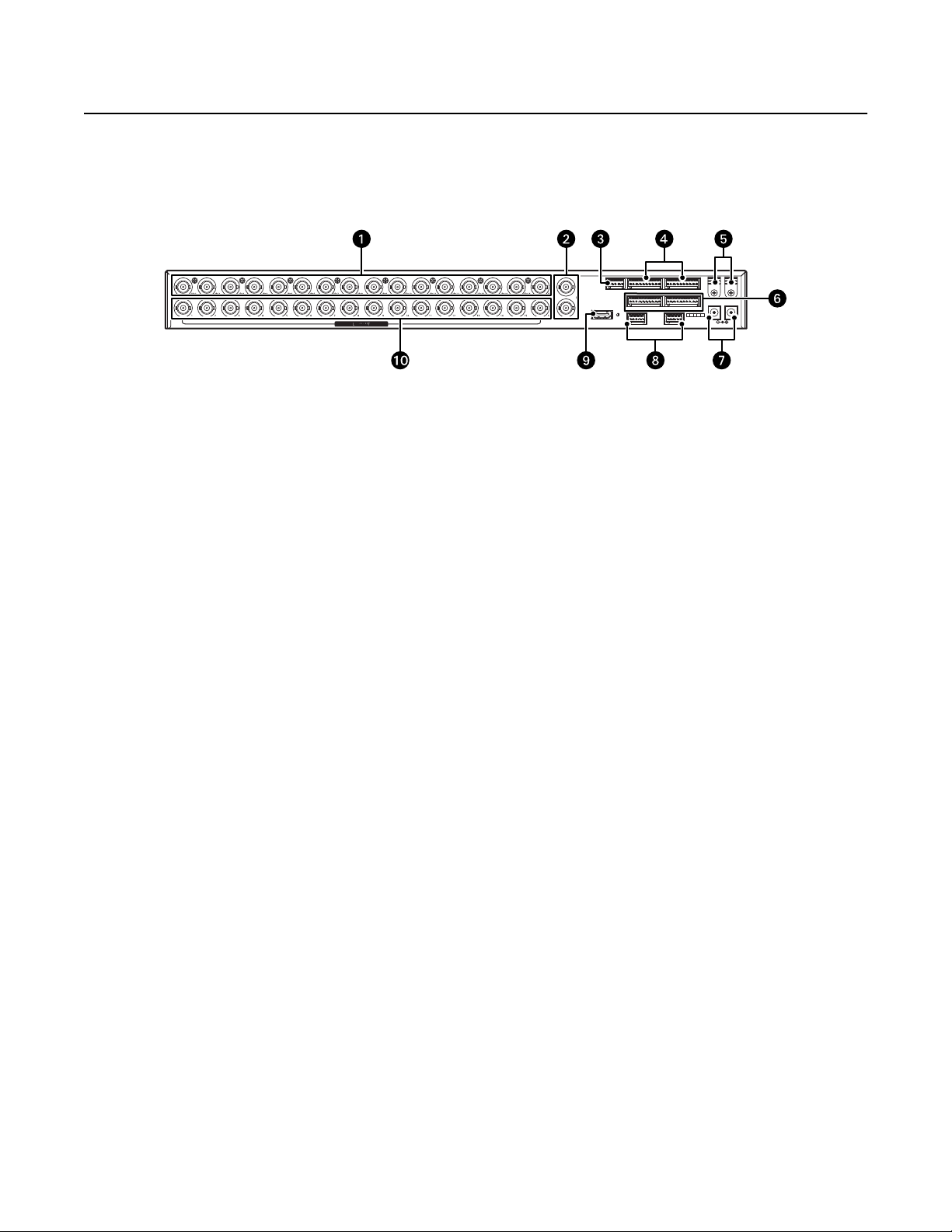
Figure 1. Rear Panel Layout
u Video Input Connectors (CH1 to CH16, BNC type): Connects to cameras.
v Spot Monitor Outputs (Vout1, Vout2, BNC type): Connects to devices such as a VCRs or monitors with a VIDEO IN connector. Through
Digital Sentry software, you can select from the following display options:
ENC5416
• Vout1 asa1x1,2x2,3x3or4x4matrix displaying input CH1 to CH8.
• Vout2 asa1x1,2x2,3x3or4x4matrix displaying input CH9 to CH16.
NOTE: Upper Vout1 and lower Vout1 (upper Vout2 and lower Vout2) are physically connected and recognized as the same connector.
ENC5516
• Vout/MUX asa1x1,2x2,3x3or4x4matrix displaying input CH1 to CH16.
• Vout/SPOT
w Relay Outputs
x Sixteen Audio Inputs: Connect to a mono microphone.
y Power Cable Clip: Secures the adapter cable.
U Sixteen Alarm Inputs
V 12 VDC Input Connector (s): Connects to the 12 VDC, 6 A adapter (supplied).
NOTE: The ENC5516 provides two connectors for redundancy, only one connector is required.
W Two RS-485/RS-422: Connects to a device such as a PTZ camera.
X DSSRV Data Cable Connector: Connects to the host card. Order ENC5400-4PORT to acquire cable.
at Video Loop Output Connectors (CH1 to CH16, BNC type): Connects to devices such as VCRs or monitors with a VIDEO IN connector.
Each loop out connector corresponds to each video input connector with the same number.
C4694M-C (6/14) 6
Page 7

RELAY OUTPUT
Figure 2 provides a close-up view of the relay outputs. The relay output connects to devices such as buzzers or alarm lamps.
C1234
DO AIN
Figure 2. Relay Outputs
RS-485/RS-422 CONNECTORS
Figure 3 provides a close-up view of the RS-485 and RS-422 connectors. The RS-485 and RS-422 connectors connect to devices such as PTZ
cameras.
RS-485/422
1
Figure 3. RS-485/RS-422 Connectors
Table A shows the connections for the RS-485 and RS-422 connectors.
Table A. RS-485 and RS-422 Connections
Connections RS-485 RS-422
G GND GND
Tx+ Trx+ Rx+
Tx– Trx– Rx–
Rx+ — Tx+
Rx– — Tx–
2
AUDIO INPUTS
Figure 4 provides a close-up view of the audio inputs. The audio inputs connect to devices such as mono microphones.
G 9 10 11 12 G 13 14 15 16G 1 2 3 4 G 5 6 7 8
Figure 4. Audio Inputs
ALARM INPUTS
Figure 5 provides a close-up view of the alarm inputs.
C C 9 10 11 12 13 14 15 16C C 1 2 3 4 5 6 7 8
Figure 5. Alarm Inputs
7 C4694M-C (6/14)
Page 8

FRONT PANEL CONTROLS AND INDICATORS
Standby Power Link
PWR1 PWR2 LINK
u System Status LEDs:
Aux
VIDEO INPUT
Figure 6. Front Panel Without Bezel (ENC5416)
INFO
VIDEO INPUT
Figure 7. Front Panel Without Bezel (ENC5516)
Figure 8. Front Panel with Bezel
ENC5416 ENC5516
Standby PWR1 Illuminates when the power source is connected.
Power PWR2 Illuminates when the power source is connected.
Link LINK Illuminates when the host system recognizes the encoder.
Aux INFO Blinks during the firmware update.
v Video Input Status LEDs: Each LED (1 to 16) lights up when the video signal of each channel is connected to its corresponding port.
C4694M-C (6/14) 8
Page 9

Before You Begin
PACKAGE CONTENTS
Figure 9. Major Package Components
u ENC5516 Encoder
v Accessory Pack (refer to Figure 10, page 10)
w ENC5516-LIT Literature Kit: Includes Important Safety
Instructions and resource disc
9 C4694M-C (6/14)
Page 10

NOTE: Order the ENC400-4PORT capture card to acquire the DSSVR data cable.
USER SUPPLIED PARTS LIST
The following installation tools and parts are needed, but not supplied:
• Power source (110/220 VAC)
• Small Phillips screwdriver for rack installation
• ESD wrist strap
Figure 10. Accessory Pack
u Power Adaptor (1 ea.)
v Standard US Power Cord (1 ea.)
w Power Cord (based on country designation (1 ea.)
NOTE: Units shipped to China do not include power cords.
x Mounting Brackets (2 ea.) and Hardware
y 10-pin Terminal Blocks (4 ea.)
U 5-pin Terminal Blocks (3 ea.)
V Rubber Feet (4 ea.)
C4694M-C (6/14) 10
Page 11

Installation
MOUNTING IN A RACK
The encoder mounts into an industry-standard 48 cm (19-inch) equipment rack. The encoder occupies 1 RU (4.45 cm or 1.75 inches) of vertical
rack space. The hardware necessary to mount the encoder into a rack is supplied with the unit.
The rack must meet the following requirements:
• Rack standard: 48 cm (19 inches), EIA-310-D compliant (rear column required)
• Rack column depth: 50.8 to 76.2 cm (20 to 30 inches)
• Column mounting hole provisions: 10-32 UNF-2B threaded holes or square window holes on front and rear columns
• Door Systems (optional): Front doors must have at least 5.1 cm (2 inches) between the encoder front bezel and the inside of the door.
Rear doors can be used only on rack columns that are more than 66 cm (26 inches) deep.
WARNINGS:
• Make sure the encoder is level.
• Slots and openings in the cabinet provide ventilation to prevent the unit from overheating. Do not block these openings.
To install the encoder in a rack:
1. Remove the three Phillips flat head screws from each side of the unit. Set the screws aside.
2. Align the three screw holes in the mounting brackets with the threaded holes on the left and the right sides of the chassis (refer to
Figure 11).
3. Using the six Phillips flat head screws, attach the mounting brackets to each side of the chassis.
4. Insert and tighten the Phillips flat head screws you removed earlier.
Figure 11. Attaching the Mounting Brackets to the Unit
5. Align the two mounting bracket holes on each side with the screw holes on the rack.
6. Insert and tighten the Phillips pan head screws (not supplied) to secure the unit in the rack.
11 C4694M-C (6/14)
Page 12

CONNECTING THE POWER SUPPLY
1. Connect the power adapter cord to the power supply receptacle on the rear panel.
2. Remove the power adapter cord clip by removing the Phillips flat head screw. Set the screw aside.
3. Wrap the clip around the power adapter cord below the ferrite bead.
4. Align the holes on the clip and chassis. Rotate the clip 90 degrees to the right from the original position. This will allow clearance for the
cord.
5. Insert and tighten the Phillips flat head screw.
NOTE: Make sure that the power adapter cord is securely connected after reinstalling the clip.
6. Connect one end of the power cord to the power adapter.
7. Connect the other end of the power cord to the appropriate power source.
NOTE: It is recommended that you use an uninterruptible power supply (UPS) to maintain a limited amount of backup battery power if the
main power fails.
CONNECTING VIDEO, INPUTS, AND OUTPUTS
Connect cameras to the video input connectors on the encoder rear panel using 75 ohm video coaxial cables with a BNC connector. Each video
channel input can be looped to other equipment such as a CRT monitor through video loop out connectors and external video output connectors.
ALARM INPUTS
There are two types of alarm interfaces that can be controlled by software: voltage and relay.
NOTE: Before connecting alarms, check the driving voltage and the output signal alarm type. Since each connection is different according to
alarm type, be careful when connecting each alarm.
CONNECTING AUDIO
Connect devices such as microphones to audio inputs 1 to 16 (Ain1 to Ain16). A pre-amp is recommended to ensure audio quality.
AUDIO IN 1
AUDIO IN 16
GND
Figure 12. Audio Inputs
The audio input range is a minimum of 0.01 amps and a maximum of 3.30 amps.
MICROPHONE 1
MICROPHONE 16
C4694M-C (6/14) 12
Page 13

CONNECTING PTZ CAMERAS
The following table describes the PTZ camera connections for RS-485 and RS-422.
Table B. RS-485 and RS-422 PTZ Camera Connections
Encoder PTZ Camera
RS-485
GND GND
T+ TRx+ (DATA+)
T– TRx– (DATA–)
R+ —
R– —
RS-422
GND GND
Tx+ Rx+
Tx– Rx–
Rx+ Tx+
Rx– Tx–
CONNECTING TO A DS NVR (DSSRV, DSSRV-DVD)
The DSSRV data cable (shipped with the ENC5400-4PORT card) has a dual connector on one end and two connectors on the other end. Each
DSSRV data cable can support two encoders. Refer to Configuration on page 15 to configure a new or existing system after the units are
connected.
2-PORT CONNECTION
1. If already turned on, turn off the DS NVR by performing the following steps:
®
a. In Microsoft
b. Make sure the unit is turned off completely.
NOTE: The encoder(s) can remain on during this process.
2. Connect the dual connector end of the DSSRV data cable (not supplied) to the primary capture card on the DS NVR (refer to Figure 13).
3. Connect the other end of the DSSRV data cable to the encoder(s).
NOTE: Refer to Figure 13 for the proper connection. Make sure the cords are aligned from the dual connector to each individual connector.
• Primary capture card: The top DSSRV data cable port on the primary capture card is for Encoder 1. The bottom DSSRV data cable
port is for Encoder 2. The primary capture card connects to the 20-pin ribbon connector slot in 2-port kits.
• Secondary capture card: The secondary capture card is the daughter card that connects to the 20-pin ribbon connector slot in 4-port
kits.
Windows®, click Start, and then click Shut Down. This allows an orderly closing of the operating system.
ENC5516
DSSRV
VOUT/MUX
VOUT/SPOT
VOUT/MUX
VOUT/SPOT
DS-SVR
DATA CABLE
DS-SVR
DATA CABLE
G T+ T- R+ RG: GND
T+:TRX+ T-:TRXR+:RX+ R-:RX-
G T+ T- R+ RG: GND
T+:TRX+ T-:TRXR+:RX+ R-:RX-
PWR1 PWR2
ENC5516
PWR1 PWR2
Figure 13. Connecting the DSSRV and Encoder(s)
13 C4694M-C (6/14)
Page 14

4. When connections are completed, press the power button on the front of the DS NVR to turn the unit on.
WARNING: Disconnecting an encoder from the DSSRV while the unit is turned on might cause the application or operating system to stop
responding with an error that appears as a blue screen. To recover from the error, you must restart the DSSRV. Your DSSRV will not record
video until the unit has fully restarted. Ensure that the screws on the data cables connecting the encoders to theDSSRV areproperly fastened
to prevent this error from occurring.
4-PORT CONNECTION
1. If already turned on, turn off the DS NVR by performing the following steps:
a. In Windows, click Start, then click Shut Down. This allows an orderly closing of the operating system.
b. Make sure the unit is turned off completely.
NOTE: The encoder(s) can remain on during this process.
2. Connect the dual connector end of the first DSSRV data cable (not supplied) to the primary capture card on the DS NVR.
3. Connect the dual connector end of the second DSSRV data cable (not supplied) to the secondary capture card on the DS NVR.
4. Connect the other ends of the DSSRV data cables to the encoders. Connect up to four encoders to a DS NVR.
NOTE: Figure 13 on page 13 shows the proper connection for the primary capture card. The configuration is the same for the secondary
capture card. Make sure the cords are aligned from the dual connector on the primary and secondary capture cards to each individual
connector.
• Primary capture card: The top DSSRV data cable port on the primary capture card is for Encoder 1. The bottom DSSRV data cable
port is for Encoder 2.
• Secondary capture card: The top DSSRV data cable port on the secondary capture card is for Encoder 3. The bottom DSSRV data
cable port is for Encoder 4.
5. When connections are completed, press the power button on the front of the DS NVR to turn on the unit.
C4694M-C (6/14) 14
Page 15

Configuration
CONFIGURING A NEW SYSTEM
Refer to the Digital Sentry DS NVs Installation manual for complete information on the installation and configuration of Digital Sentry software.
1. Install and power up all encoders connected to a DS NVR.
2. Click the DS Quick Setup icon on your desktop. The DS Quick Setup Wizard appears.
3. Click the Next button. The Computer Settings dialog box appears.
4. Select “New Setup – Delete Existing Configuration and Video.” A dialog box appears stating that all video will be deleted.
5. The system scans for new hardware and the Computer Settings dialog displays showing the Computer name and IP address. Click Next.
6. The Local Hardware dialog box appears (refer to Figure 14 on page 15) showing the detected hardware (encoders), the number of cameras
connected to each encoder, and the frame rate The encoder will be identified as an ENC5516 or HP3000 (ENC5416) driver.
Figure 14. Local Hardware Dialog Box
7. Click the Next button.
15 C4694M-C (6/14)
Page 16

8. The Serial Port Settings dialog box appears (refer to Figure 15 on page 16). This allows you to enable Pelco PTZ cameras on selected COM
ports. There are two COM ports per encoder.
Figure 15. Serial Port Settings Dialog Box
9. Click the Next button. The Storage Locations dialog box appears.
Figure 16. Storage Locations Dialog Box
10. Select the desired check box(es) for the drive in which to save video, and then click the Next button.
11. Continue with the remainder of the setup.
NOTE: Additional configuration is required. Refer to the Digital Sentry DSAdmin Operation/Configuration manual for additional instructions.
C4694M-C (6/14) 16
Page 17

CONFIGURING SERIAL PORTS
1. Select the Serial Ports tab to find serial port configuration. For a normal installation, DS Quick Setup configures the system.
2. For manually configuring serial ports:
a. From Unused COM Ports, select the COM port, and click Add.
b. Select the Interface Type “PTZ”.
c. Select PTZ Type “Pelco D, No Parity”.
d. Click the Active check box, and click Save.
e. Restart the system or the Video Server Service.
3. Proceed to Configuring Coaxitron.
Figure 17. Serial Ports Window
CONFIGURING PTZ AND COAXITRON (ENC5516)
The Coaxitron board hooks into the serial port and re-interprets Pelco D protocol serial commands (9600 N 8 1), injecting Coaxitron into the video
input stream associated with D protocol address. A serial command for D address 5 will be sent out video input 5.
1. Find the COM Port assignments by accessing the DS RealVue Diagnostics Tool (included in the DS Suite). DS RealVue displays each encoder
attached within a grid (shown as Boards 1 through 4).
a. Disable the DigitalSentry VideoServer service. From the Run program, type “services.msc” in the Open field. Click OK, and the
Services dialog opens. Scroll to the DigitalSentry VideoServer service, and click Stop. During the time in which the DigitalSentry
VideoServer Service is disabled, video stops operating.
b. Each encoder is designated two rows. When a segment in the grid is selected, the main screen at the top changes, displaying the
Board, Camera and COM port. Note the COM port assignments for each encoder.
c. Restart the DigitalSentry VideoServer service through the Services dialog.
2. From DS Admin, go to the systems VAU, and select the Camera.
3. Go to the PTZ tab, and select each of the cameras from “Camera connected to port” and attempt to access the camera using PTZ controls.
17 C4694M-C (6/14)
Page 18

Specifications
MODELS
ENC5416/ENC5516 16-channel, H.264, direct-attached video encoder; requires a ENC5400-4PORT capture card, which are
SUPPLIED ACCESSORIES
Power Adapter 12 V through autoranging DC (12 V, 6 A); the ENC5516 allows for redundant power
Power Cord Based on country designation
Terminal Block 3, 5-pin terminal blocks
Rack Mount 2, mounting brackets
Rubber Feet 4 (for desktop)
VIDEO/AUDIO
Video Standards NTSC/PAL
Video Encoding H.264, Main profile
Video Resolutions
Analog Cameras NTSC PAL
D1 720 x 480 720 x 576
2CIF 720 x 240 720 x 288
CIF 352 x 120 352 x 288
Video Input 16 BNC video inputs
Video Output
ENC5416: Four BNC connectors for spot monitor input, 16 BNC looping video output
ENC5516: Two BNC connectors, one connector for a video multiplexer (MUX) and the other for a spot monitor
Audio Input 16 channels
Audio Format Pulse code modulation (PCM)
Sampling Resolution 8- or 16-bit
Sampling Frequency 4, 8, 16, or 32 kHz
sold separately
NOTE: Units shipped to China do not include power cords.
4, 10-pin terminal blocks
PTZ CONTROL
Interface Two RS-422, RS-485, video in
Protocol Pelco P, Pelco D and Pelco C (ENC5516)
ALARMS/RELAYS
Alarms In 16
Relays Out 4
POWER
Power Consumption
Input Voltage 12 VDC
Current 2130 mA
Power 25.56 W (maximum ±5%)
FRONT PANEL INDICATORS
ENC5416 ENC5516
Standby PWR1 Green when the power source is connected
Power PWR2 Green when the power source is connected
Link LINK Green when host recognizes the encoder
Aux INFO Blinks green when the firmware is updating
Video Input (1 to 16 Channels) Green when detecting an active video signal on the corresponding Video Input Connector
ENVIRONMENTAL
Operating Temperature 0° to 60°C (32° to 140°F)
Operating Humidity 85% maximum relative humidity, noncondensing
PHYSICAL
Dimensions 18.9 x 44.2 x 4.4 cm (7.5" D x 17.4" W x 1.7" H)
Unit Weight 2.7 kg (6 lb)
C4694M-C (6/14) 18
Page 19

This equipment contains electrical or electronic components that must be recycled properly to comply with Directive 2002/96/EC of the
European Union regarding the disposal of waste electrical and electronic equipment (WEEE). Contact your local dealer for procedures for
recycling this equipment.
REVISION HISTORY
Manual # Date Comments
C4694M 10/11 Original version.
C4694M-A 11/12 Added a warning to the Connecting to a DS NVR (DSSRV, DSSRV-DVD) section.
C4694M-B 6/13 Corrected pinout illustrations.
C4694M-C 6/14 Added the ENC5516, removed QCIF references, removed ENC5400-2PORT, replaced PCIe cable with DSSRV data cable, corrected text that states DSSRV data cable
Pelco, the Pelco logo, and other trademarks associated with Pelco products referred to in this publication are trademarks of Pelco, Inc. or its affiliates. © Copyright 2014, Pelco, Inc.
ONVIF and the ONVIF logo are trademarks of ONVIF Inc. All other product names and services are the property of their respective companies. All rights reserved.
Product specifications and availability are subject to change without notice.
is shipped with the ENC5516.
Page 20

Pelco by Schneider Electric 3500 Pelco Way Clovis, California 93612-5699 United States
USA & Canada Tel (800) 289-9100 Fax (800) 289-9150
International Tel +1 (559) 292-1981 Fax +1 (559) 348-1120
www.pelco.com www.pelco.com/community
 Loading...