

Page 1
1
EHS8000 Series
Stainless Steel
Enclosures
Installation Manual
C3492M 11/18
Page 2

2
Contents
Important Notices ................................................................................................................................ 3
Regulatory Notices ...................................................................................................................... 3
Radio and Television Interference ............................................................................................ 3
Korean Class A EMC .................................................................................................................. 3
Warranty Statement .................................................................................................................... 3
Important Safety Instructions ..................................................................................................... 4
Introduction ........................................................................................................................................... 5
Models ........................................................................................................................................... 6
Included Mount ............................................................................................................................ 6
Optional Mounts .......................................................................................................................... 6
Getting Started ..................................................................................................................................... 7
EHS8000 Series Models ............................................................................................................ 8
Supplied Parts List .............................................................................................................. 8
User-Supplied Parts List .................................................................................................... 8
Product Label ....................................................................................................................... 8
EHS8000 Series Product Overview ................................................................................................. 9
Installation: 24V Models (EHS8000-2-H) ...................................................................................... 11
Installation: Mains Models (EHS8000-3-H) ................................................................................... 17
Installation: PoE Models (EHS8000-P-H) ...................................................................................... 22
Installing the Sun Shield ................................................................................................................... 27
Installing the EMS8000 Mount ........................................................................................................ 28
Installing the EPS8000 Pole Mount Adapter ................................................................................. 30
Supplied Parts List ............................................................................................................ 30
Page 3
3
Important Notices
For more information about Pelco’s product-specific important notices and thereto related information,
refer to www.pelco.com/legal.
Regulatory Notices
This device complies with Part 15 of the FCC Rules. Operation is subject to the following two conditions:
(1) this device may not cause harmful interference, and (2) this device must accept any interference
received, including interference that may cause undesired operation.
Radio and Television Interference
This equipment has been tested and found to comply with the limits of a Class A digital device, pursuant
to Part 15 of the FCC rules. These limits are designed to provide reasonable protection against harmful
interference when the equipment is operated in a commercial environment. This equipment generates,
uses, and can radiate radio frequency energy and, if not installed and used in accordance with the
instruction manual, may cause harmful interference to radio communications. Operation of this
equipment in a residential area is likely to cause harmful interference in which case the user will be
required to correct the interference at his own expense.
Changes and modifications not expressly approved by the manufacturer or registrant of this equipment
can void your authority to operate this equipment under Federal Communications Commission’s rules.
CAN ICES-3(A)/NMB-3(A).
Korean Class A EMC
Warranty Statement
For information about Pelco’s product warranty and thereto related information, refer to www.pelco.com/
warranty.
Page 4

4
Important Safety Instructions
1. This product shall be installed by a qualified service person and the installation shall conform to local
codes.
2. Read these instructions.
3. Keep these instructions.
4. Heed all warnings.
5. Follow all instructions.
6. Clean only with dry cloth.
7. Do not block any ventilation openings. Install in accordance with the manufacturer’s instructions.
8. Do not install near any heat sources such as radiators, heat registers, stoves, or other apparatus
(including amplifiers) that produce heat.
9. Only use attachments/accessories specified by the manufacturer.
10. Refer all servicing to qualified service personnel. Servicing is required when the apparatus has been
damaged in any way, such as power-supply cord or plug is damaged, liquid has been spilled or
objects have fallen into the apparatus, the apparatus has been exposed to rain or moisture, does not
operate normally, or has been dropped.
11. Unless the unit is specifically marked as a NEMA Type 3, 3R, 3S, 4, 4X, 6, or 6P enclosure, it is
designed for indoor use only and it must not be installed where exposed to rain and moisture.
12. Use only installation methods and materials capable of supporting four times the maximum specified
load.
13. Use stainless steel hardware to fasten the mount to outdoor surfaces.
14. An all-pole main switch with a contact separation of at least 3 mm in each pole shall be incorporated
in the electrical installation of the building.
15. A readily accessible disconnect device shall be incorporated in the building installation wiring.
16. This product requires a surge protector device (SPD) or surge arrester as part of the installation to
address transient overvoltages exceeding Overvoltage Category II, 2500 Vpk.
CAUTION: These servicing instructions are for use by qualified service personnel only. To reduce the risk
of electric shock do not perform any servicing other that contained in the operating instructions unless you
are qualified to do so.
The product and/or manual may bear the following marks:
This symbol indicates that dangerous voltage constituting a risk of electric shock is present
within this unit.
This symbol indicates that there are important operating and maintenance instructions in the
literature accompanying this unit.
Page 5

5
Introduction
The EHS8000 Series is a rugged and highly reliable camera enclosure with an adjustable sun shroud
designed for easy installation. Constructed from 316L stainless steel to IP66/IP68 and Type 6P
standards, the EHS8000 Series enclosure is designed to operate in a wide range of environments and to
protect electronic components in temperatures from -40º to 50ºC (-40º to 122ºF).
This document describes the installation and initial setup procedures to set up your EHS8000 Enclosure.
For more information about operating your camera, refer to the operation manual specific to the product.
NOTE: For additional information about product documentation in English and other languages, go to
www.pelco.com and navigate to the EHS8000 Enclosure website.
Page 6

6
Models
EHS8000-2-H Enclosure with 316L stainless steel construction: Indoor/environmental, wall mount
bracket included, heater and blower, 24 VAC, sun shroud, IP66/IP68 and Type 6P,
cable entry glands and mounting holes
EHS8000-3-H Enclosure with 316L stainless steel construction: Indoor/environmental, wall mount
bracket included, heater and blower, 220-240 VAC, sun shroud, IP66/IP68 and
Type 6P, cable entry glands and mounting holes
EHS8000-P-H Enclosure with 316L stainless steel construction: Indoor/environmental, wall mount
bracket included, heater and blower, HPoE, sun shroud, IP66/IP68 and Type 6P,
cable entry glands and mounting holes
Note: Supports 10/100 Mbps Ethernet speeds.
Included Mount
EMS8000 Wall mount bracket, 316L stainless steel construction
Optional Mounts
EPS8000 Pole mount bracket for EMS8000 wall mount, 316L stainless steel construction
Page 7

7
Getting Started
Before installing your EHS8000 enclosure, thoroughly familiarize yourself with the information in the
installation section of this manual.
NOTE: Please refer to your camera installation manual for installing and configuring the camera within
the enclosure.
Page 8

8
EHS8000 Series Models
Supplied Parts List
Qty Description
1 EHS8000 Series enclosure
1 EHS8000 Installation manual
2 M20 gland fitting
1 EMS8000 wall mount
3 Socket head screws, M8 x 20 mm (for enclosure mounting)
4 M5 x 12 mm socket head screws (for sun shroud mounting)
6 ¼-20 screws (for camera mounting)
1 ¼-inch lock washer (for camera mounting)
1 ¼-inch steel flat washer (for camera mounting)
2 .35-inch thick plastic spacers (for camera mounting)
1 .15-inch plastic spacer (for camera mounting)
1 T25 Torx wrench
1 Ethernet patch cable (PoE models only)
1 5 mm hex key wrench
1 6 mm hex key wrench
User-Supplied Parts List
In addition to the standard tools and cables required for a video security installation, you will need to
provide the following items:
Qty Description
1 CAT5e or better Ethernet cable
1 Phillips screwdriver
1 RJ45 connector
1 Ring terminal connector for Earth ground wire (Note: Optional part for 24V and PoE models)
1 Flat-head screwdriver
1 Crimping tool
4 Screws for mounting EMS8000 wall mount (Note: The mounting hardware is not provided.)
Product Label
The product label lists the model number, date code, and serial number. This information might be
required for setup. A product label is located on the inside of the enclosure and on the side of the
product box.
Page 9
9
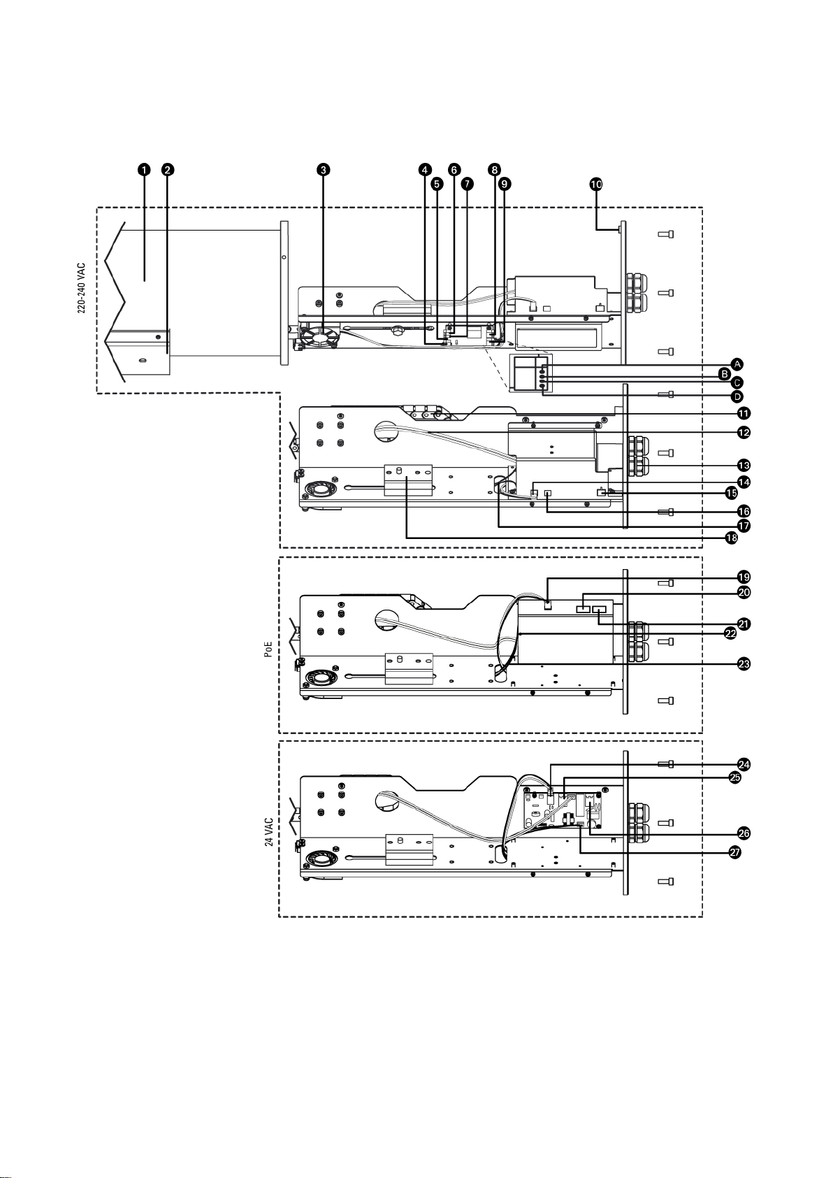
EHS8000 Series Product Overview
Page 10

10
1. Camera housing
2. Mounting bracket
3. Fan
4. 12 VDC to wiper/washer board
5. Wiper control Input (not used)
6. Washer control input (not used)
7. Washer control switch output (not used)
8. Pressure sensor connector (not used)
9. Tamper contact switch
A. Tamper contact Switch Out+ (pre-installed)
B. Tamper contact Switch Out– (pre-installed)
C. Tamper contact Switch IN+ (Customer will install/connect if used)
D. Tamper contact Switch IN – (Customer will install/connect if used)
10. Primary Earth ground
11. Cable guide
12. Window defroster guide
13. Waterproof cable gland
14. 12 VDC to wiper/washer board (pre-installed)
15. 220-240 VAC input
16. 12 VDC output to camera
17. Tamper contact switch wire
18. Camera mounting spacers
19. 12 VDC to wiper/washer board (pre-installed)
20. PoE output to camera
21. HPoE input
22. Power LED indicator
23. Tamper contact switch wire
24. 12 VDC to wiper/washer board (pre-installed)
25. 24 VAC output to camera
26. 24 VAC input
27. Heater connector (pre-installed)
Page 11

11
Installation: 24V Models (EHS8000-2-H)
1. Using the supplied T25 Torx wrench, remove the (6) M5 x 18 mm screws from the rear mounting
plate of the enclosure. Slide the rear plate away from the enclosure until it stops, exposing the
camera mounting sled and the wiring connections.
2. For installing an IP camera, pass an Ethernet cable (CAT5E or better and marked with CL3 Outdoor)
through the gland fitting on the rear of the enclosure. Please refer to the camera manual for other
types of cameras for installation.
IMPORTANT:
Optional bonding connection for 24V model
(EHS8000-2-H)
Page 12

12
You may need to remove the RJ-45 connector, and use a crimping tool to connect the Ethernet wires
to an RJ-45 connector inside the enclosure. Use an Ethernet cable of the width of 5-6.5mm. Follow
the T568B pinout show below and make sure both ends of the Ethernet cable match (Straight
Through Cable).
Page 13

13
3. Insert the stripped wires from the 24VAC in line into the power input on the electric board as shown
below and tighten in place.
Page 14

14
4. Connect the 24 VAC out on the board to the power connector provided with your camera.
5. If you are not using the second cable gland fitting, insert a plug or a piece of cable into the hole or
remove the fitting completely and replace with a hole plug. When complete, tighten up the gland
fitting nuts.
Page 15

15
6. Attach your camera and lens to the camera mounting sled using (1) ¼-inch flat washer, (1) ¼-inch
lock washer, and (1) ¼-20 screw of the appropriate length (supplied). By using various combinations
of the (1) thin plastic spacer and (2) thick plastic spacers, you can adjust the height of your camera
and lens from .15”-.87” to get them close to the center of the viewing window, if needed. Once the
camera height is finalized, adjust the position of the camera/lens assembly on the camera mounting
sled so that the lens sits as close as possible to the viewing window when it is inside the enclosure.
Page 16

16
7. Connect the Ethernet cable and power plug to the camera.
8. Push on the rear mounting plate and slide the camera mounting sled all the way back into the
enclosure. Reinstall the (6) M5 x 18 mm screws into the rear plate and tighten the screws using the
wrench. Screws should be tightened to 4 N-m (35.4 lbf-in).
Page 17

17
Installation: Mains Models (EHS8000-3-H)
1. Using the supplied T25 Torx wrench, remove the (6) M5 x 18 mm screws from the rear mounting
plate of the enclosure. Slide the rear plate away from the enclosure until it stops, exposing the
camera mounting sled and the pcb connections.
2. For installing an IP camera, pass an Ethernet cable (CAT5E or better and marked with CL3 outdoor)
through the gland fitting on the rear of the enclosure. Please refer to the camera manual for other
types of cameras for installation. Pass the Mains wiring through the other gland fitting. For safety
reasons, please do not run high voltage wires with low voltage wires through the same gland and
wires shall comply to the following:
a. Only use specific suitable high voltage wires according to ANSI/NFPA 70 National Electrical
Code (NEC) permanent wiring connection. For supply connections, use wire suitable for at
least 85º C and 12 to 14 AWG.
b. High voltage wires must be covered by 0.4 mm thick UL recognized tubing.
c. RJ-45 cable must be covered by 0.4 mm thick UL recognized tubing.
Page 18

18
You may need to remove the RJ-45 connector, and use a crimping tool to connect the Ethernet wires
to an RJ-45 connector inside the enclosure. Use an Ethernet cable of the width of 5-6.5mm. Follow
the T568B pinout shown below and make sure both ends of the Ethernet cable match (Straight
Through Cable).
Page 19

19
3. Insert the stripped power wires (220-240 VAC) from the mains into the power input on the enclosure
as shown below and tighten in place. Use a suitable wire ring terminal (not supplied) to attach the
Earth ground line onto the inside of the rear mounting plate of the enclosure. If there are any other
wires connected to the earth ground screw, please make sure that the incoming earth ground must
be the first wire to contact the enclosure.
4. Connect the 12V DC and Ground to the plug for your camera as shown. Insure the + and ground
match up with your camera input.
5. When done, tighten up the gland fitting nuts.
Page 20

20
6. Attach your camera and lens to the camera mounting sled using (1) ¼-inch flat washer, (1) ¼-inch
lock washer, and (1) ¼-20 screw of the appropriate length (supplied). By using various combinations
of the (1) thin plastic spacer and (2) thick plastic spacers, you can adjust the height of your camera
and lens from .15”-.87” to get them close to the center of the viewing window, if needed. Once the
camera height is finalized, adjust the position of the camera/lens assembly on the camera mounting
sled so that the lens sits as close as possible to the viewing window when it is inside the enclosure.
Page 21

21
7. Connect the Ethernet cable and power plug to the camera.
8. Push on the rear mounting plate and slide the camera mounting sled all the way back into the
enclosure. Reinstall the (6) M5 x 18 mm screws into the rear plate and tighten the screws using the
wrench. Screws should be tightened to 4 N-m (35.4 lbf-in).
Page 22

22
Installation: PoE Models (EHS8000-P-H)
1. Using the supplied T25 Torx wrench, remove the (6) M5 x 18 mm screws from the rear mounting
plate of the enclosure. Slide the rear plate away from the enclosure until it stops, exposing the
camera mounting sled and the pcb connections.
2. For installing an IP camera, pass an Ethernet cable (CAT5E or better and marked with CL3 outdoor)
through the gland fitting on the rear of the enclosure. Please refer to the camera manual for other
types of cameras for installation.
IMPORTANT:
Optional bonding connection for PoE model
(EHS8000-P-H), but the product was tested
with one port and without the bonding
connection per KN32.
Page 23

23
You may need to remove the RJ-45 connector, and use a crimping tool to connect the Ethernet wires
to an RJ-45 connector inside the enclosure. Use an Ethernet cable of the width of 5-6.5mm. Follow
the T568B pinout shown below and make sure both ends of the Ethernet cable match (Straight
Through Cable).
Page 24

24
3. Insert the newly crimped RJ45 connector to the POE input port as shown below.
4. If you are not using the second cable gland fitting, insert a plug or a piece of cable into the hole or
remove the fitting completely and replace with a hole plug. When done, tighten up the gland fitting
nuts.
Page 25

25
5. Attach your camera and lens to the camera mounting sled using (1) ¼-inch flat washer, (1) ¼-inch
lock washer, and (1) ¼-20 screw of the appropriate length (supplied). By using various combinations
of the (1) thin plastic spacer and (2) thick plastic spacers, you can adjust the height of your camera
and lens from .15”-.87” to get them close to the center of the viewing window, if needed. Once the
camera height is finalized, adjust the position of the camera/lens assembly on the camera mounting
sled so that the lens sits as close as possible to the viewing window when it is inside the enclosure.
Page 26

26
6. Connect the supplied Ethernet patch cable from POE output to the camera POE input. Please use
POE (IEEE802.3af) enabled cameras. There will be a risk of damage to the camera if a non-
compliant POE camera is used.
7. Push on the rear mounting plate and slide the camera mounting sled all the way back into the
enclosure. Reinstall the (6) M5 x 18 mm screws into the rear plate and tighten the screws using the
wrench. Screws should be tightened to 4 N-m (35.4 lbf-in).
Page 27

27
Installing the Sun Shield
1. Set the sun shield on top of the enclosure with the extended surface towards the front of the
enclosure. Align the slots in the sun shield with the 4 threaded mounting holes in the front and rear of
the enclosure.
2. Install (1) M5 x 12 mm screw into each of the 4 mounting slots on the sun shield and thread the
screws into the enclosure. Adjust the position of the sun shield forwards or backwards as needed and
then tighten the screws using a Philips screwdriver.
Page 28

28
Installing the EMS8000 Mount
1. Install the EMS8000 wall mount flush against a flat surface. Drill mounting holes and a cable routing
hole (if needed) on the mounting surface using the mounting flange of the wall mount as a template.
Install the mount using four screws (not supplied) of appropriate type and size for the surface being
mounted to. The mount and enclosure must be installed above ground level of more than 3 meters
(9.84 feet).
2. Lift the enclosure up to the installation position and mount the enclosure onto the installed wall
bracket. Line up the mounting slots in the center of the wall mount bracket with the threaded holes in
the bottom mounting bracket of the enclosure. Secure the connection by installing the supplied (3)
M8 x 20 mm socket screws through the tilt bracket and into the bottom mount bracket on the
enclosure. Use the supplied 6 mm hex key wrench or a socket to tighten the 3 screws. Due to the
weight of the enclosure, it is best to have two people mounting the enclosure.
Page 29

29
3. To adjust the position of the enclosure, use the supplied 5 mm hex key wrench or a socket to loosen
the pan and tilt adjustment screws. Pan adjustment is done by loosening the 3 screws on the
underside of the wall mount bracket. Tilt adjustment is done by loosening the 4 screws on each side
of the tilt bracket. Position the enclosure as needed and retighten all adjustment screws.
Page 30

30
Installing the EPS8000 Pole Mount Adapter
Supplied Parts List
Qty Description
4 Screws, stainless steel, M8 x 15 mm, hex socket head
2 Adjustable straps, stainless steel, 80 mm to 160 mm
To attach the EPS8000 pole mount adapter to a pole, perform the following steps:
1. Determine the placement of the EPS8000 on the pole by measuring the height of the CCTV
equipment to be mounted.
2. Position the EPS8000 on the pole and secure with the stainless steel mounting straps (provided).
WARNING: Only mount one camera system per set of stainless steel straps.
Installation torque: 35-45in.lbs.
3. Attach the EMS8000 wall mount to the pole mount using (4) M8 x 15 mm screws (supplied with the
EPS8000 pole mount).
4. Attach the EHS8000 enclosure to the wall mount according to the instructions provided on the
previous pages.
Page 31

31
Pelco Troubleshooting Contact Information
If the instructions provided fail to solve your problem, contact Pelco Product Support at 1-800-289-9100
(USA and Canada) or +1-559-292-1981 (international) for assistance. Be sure to have the serial
number and model number available when calling.
Do not try to repair the unit yourself. Leave maintenance and repairs to qualified technical personnel
only.
Page 32

32
 Loading...