

Page 1
INSTALLATION
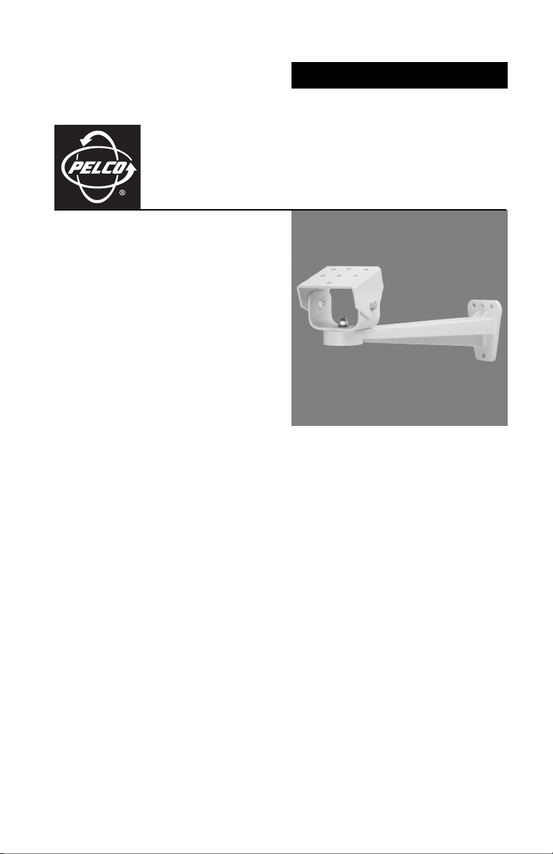
EM1450 Light Duty Wall Mount
C261M-B (1/08)
Page 2

Page 3

Important Safety Instructions
Prior to installation and use of this product, the following WARNINGS should be observed.
1. Read these instructions.
2. Keep these instructions.
3. Heed all warnings.
4. Follow all instructions
5. Only use attachments/accessories specified by the manufacturer.
6. Use only with the cart, stand, tripod, bracket, or table specified by the manufacturer, or sold with the
apparatus. When a cart is used, use caution when moving the cart/apparatus combination to avoid
injury from tip-over.
7. Refer all servicing to qualified service personnel. Servicing is required when the apparatus has been
damaged in any way, such as power-supply cord or plug is damaged, liquid has been spilled or
objects have fallen into the apparatus, the apparatus has been exposed to rain or moisture, does not
operate normally, or has been dropped.
8. Installation should be done only by qualified personnel and conform to all local codes.
9. Unless the unit is specifically marked as a NEMA Type 3, 3R, 3S, 4, 4X, 6, or 6P enclosure, it is
designed for indoor use only and it must not be installed where exposed to rain and moisture.
10. Use only installation methods and materials capable of supporting four times the maximum
specified load.
11. Use stainless steel hardware to fasten the mount to outdoor surfaces.
12. To prevent damage from water leakage when installing a mount outdoors on a roof or wall, apply
sealant around the bolt holes between the mount and mounting surface.
13. AN ALL-POLE MAINS SWITCH with a contact separation of at least 3 mm in each pole shall be
incorporated in the electrical installation of the building.
14. CAUTION: These servicing instructions are for use by qualified service personnel only. To reduce
the risk of electric shock do not perform any servicing other than contained in the operating
instructions unless you are qualified to do so.
15. Only use replacement parts recommended by Pelco.
The product and/or manual may bear the following marks:
This symbol indicates that dangerous voltage
constituting a risk of electric shock is present
within this unit.
This symbol indicates that there are important
operating and maintenance instructions in the
literature accompanying this unit.
Please thoroughly familiarize yourself with the information in this manual prior to installation and
operation.
CAUTION:
RISK OF ELECTRIC SHOCK.
DO NOT OPEN.
C261M-B (1/08) 3
Page 4

Description
The EM1450 light duty wall mount has been designed for use with the EH2508, EH2512, EH2515, EH3508,
EH3512, and EH3515 enclosures. It can be installed on any wall or vertical surface and is capable of
supporting up to 20 lbs (9 kg).
The EM1450 has an adjustable tilt table that allows mechanical positioning of the enclosure.
Installation
1. Drill holes in the mounting surface using the mount as a guide.
2. Attach the mount to a solid surface with three 1/4-inch diameter fasteners (not supplied), or where
there are wall studs, use on 5/16-inch fastener and one 1/4-inch fastener.
If you install the mount outdoors, rainwater could leak through the holes of the mounting bolts and
damage the wall.
To prevent water damage, seal the bolt holes with an appropriate sealant. Apply the sealant around
the bolt holes located between the mount and the mounting surface.
3. Attach the enclosure to the tilt table with the two 1/4-20 x 1/2-inch screws (provided).
4. Loosen the cap nut on the tilt table support bracket, adjust the tilt table to the desired direction, and
then retighten the cap nut. Loosen the two screws on the tilt table, adjust the tilt table to the
desired angle, and then retighten the screws.
4 C261M-B (1/08)
Page 5

Specifications
Pan Adjustment 360°
Tilt Adjustment ±75°
Construction
Mounting Arm Die-cast aluminum
Tilt Table and
Support Bracket Aluminum
Finish Gray polyester powder coat
Maximum Load 20 lb (9 kg)
Unit Weight 2 lb (0.91 kg)
Environment Indoor/outdoor
Ø 0.272 (0.69), 7X
3.47
(10.41)
1.73
(4.42)
10.53
(26.75)
11.22
(28.50)
1.50
(3.81)
Ø 0.343 (0.87),
1X
2.75
(6.99)
1.25
(3.18)
Ø 0.281 (0.713),
3X
2.86
(7.26)
3.48
(8.84)
NOTE: VALUES IN PARENTHESES ARE CENTIMETERS;
ALL OTHERS ARE INCHES.
(Design and product specifications subject to change without notice.)
1.50
(3.81)
2.00
(5.08)
3.00
(7.62)
2.84
(7.20)
5.32
(13.51)
C261M-B (1/08) 5
Page 6

REVISION HISTORY
Manual # Date Comments
C261M 3/99 Original version.
C261M 3/00 Revised Figure 1 and installation step 4 per ECO 00-5634.
C261M-A 2/06 Revised to new format. Corrected measurements in dimension drawing.
C261M-B 1/08 Revised mounting head hole pattern per ECO 07-17992.
Pelco, the Pelco logo, Camclosure, DigitalSENTRY, Endura, Esprit, ExSite, Genex, Intelli-M, Legacy, and Spectra are registered trademarks of Pelco, Inc.
Spectra III is a trademark of Pelco, Inc. © Copyright 2008, Pelco, Inc.
DLP is a registered trademark of Texas Instruments Incorporated. All rights reserved.
The materials used in the manufacture of this document and its components are compliant to the requirements
of Directive 2002/95/EC.
Page 7

PRODUCT WARRANTY AND RETURN INFORMATION
WARRANTY
Pelco will repair or replace, without charge, an y merchandise proved defective in material or workmanship for a period of one year after the date of
shipment.
Exceptions to this warranty are as noted below:
• Five years on fiber optic products and TW3000 Series unshielded twisted pair (UTP) transmission products.
• Three years on Spectra® IV products.
• Three years on Genex® Series products (multiplexers, server, and keyboard).
• Three years on DX Series digital video recorders, DVR5100 Series digital video recorders, DigitalSENTRY® Series hardware products, DVX Series
digital video recorders, NVR300 Series netwo rk video recorders, and Endura® Series distributed network-based video products.
• Three years on Camclosure® and Pelco-branded fixed camera models, except the CC3701 H-2, CC3701H-2X, CC3751H-2, CC3651H-2X, MC3651H-2,
and MC3651H-2X camera models, which ha ve a five-year warranty.
• Three years on PMCL200/300/400 Series LCD monit ors.
• Two years on standard motorized or fixed focal length lenses.
• Two years on Legacy®, CM6700/CM6800/CM9700 Series matrix, and DF5/DF8 Series fixed dome products.
• Two years on Spectra III™, Spectra Mini, Esprit®, ExSite®, and PS20 scanners, including when used in continuous motion applications.
• Two years on Esprit and WW5700 Series window wiper (excluding wiper blades).
• Two years (except lamp and color wheel) on Digital Light Processing (DLP®) displays. The lamp and color wheel will be covered for a period of
90 days. The air filter is not covered un der warranty.
• Two years on Intelli-M® eIDC controllers.
• One year (except video heads) on video cassette recorders (VCRs). Video heads will be covered for a period of six months.
• Six months on all pan and tilts, scanners, or pre set lenses used in continuous motion applications (preset scan, tour, and auto scan modes).
Pelco will warrant all replacement parts and repairs for 90 days from the date of Pelco shipment. All goods requiring warranty repair shall be sent
freight prepaid to a Pelco designated locatio n. Repairs made necessary by reason of misuse, alteration, normal wear, or accident are no t covered under
this warranty.
Pelco assumes no risk and shall be subject to no liability for damages or loss resulting from the specific use or application made of the Products. Pelco’s
liability for any claim, whether based on breach of contract, negligence, infringement of any rights of any party or product liability, relating to the
Products shall not exceed the price paid by the Dealer to Pelco for such Products. In no event will Pelco be liable for any special, incidental, or
consequential damages (including loss of use, loss of profit, and claims of third parties) however caused, whether by the negligence of Pelco or
otherwise.
The above warranty provides the Dealer with spe cific legal rights. The Dealer may also have additional right s, which are subject to variation from state
to state.
If a warranty repair is required, the Dealer must contact Pelco at (800) 289-9100 or (559) 292-1981 to obtain a Repair Authorization number (RA), and
provide the following information:
1. Model and serial number
2. Date of shipment, P.O. number, sales order number, or Pelco invoice number
3. Details of the defect or problem
If there is a dispute regarding the warranty of a product that does not fall un der the warranty conditions stated above, please include a written
explanation with the product wh en returned.
Method of return shipment shall be the same or equal to the method by which the item was received by Pelco.
RETURNS
To expedite parts returned for repair or credit, please call Pelco at (800) 289-9100 or (559) 292-1981 to obtain an authorization nu mber (CA number if
returned for credit, and RA number if returned for repair) and designated return location.
All merchandise returned for credit may be subject to a 20 percent restocking and refurbishing charge.
Goods returned for repair or credit should be clearly identified with the assigned CA or RA number and freight should be prepaid.
Page 8

Worldwide Headquarters
3500 Pelco Way
Clovis, California 93612 USA
USA & Canada
Tel: 800/289-9100
Fax: 800/289-9150
International
Tel: 1-559/292-1981
Fax: 1-559/348-1120
www.pelco.com
ISO9001
Australia|Canada|Finland|France|Germany|Italy|Macau|The Netherlands|Russia|Singapore
South Africa
Spain|Sweden|United Arab Emirates|United Kingdom|United States
|
 Loading...