

Page 1
INSTALLATION
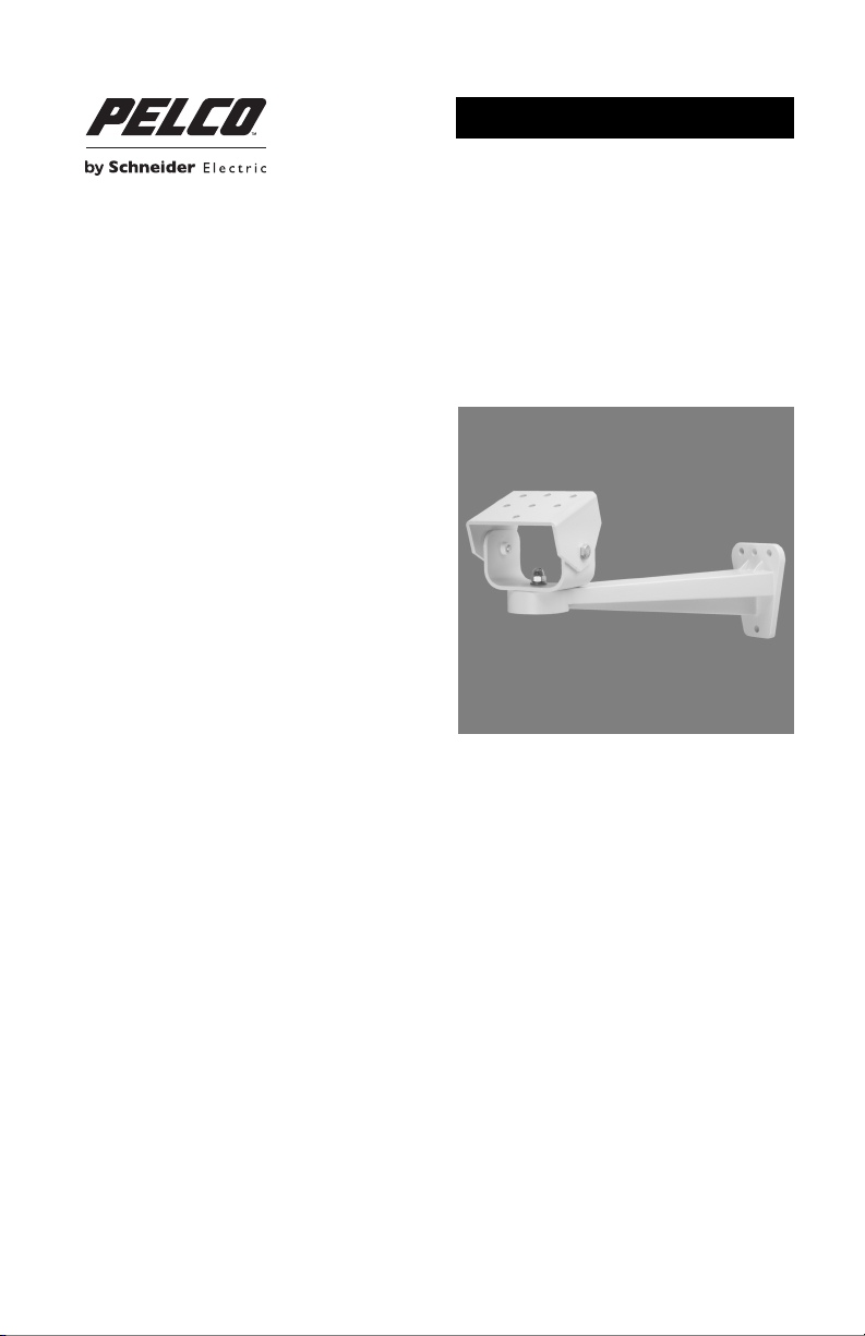
EM14 and EM1450 Light Duty Wall Mount
C261M-E (8/14)
Page 2

Page 3
Important Safety Instructions
Prior to installation and use of this product, the following WARNINGS should be observed.
1. Read these instructions.
2. Keep these instructions.
3. Heed all warnings.
4. Follow all instructions
5. Only use attachments/accessories specified by the manufacturer.
6. Installation should be done only by qualified personnel and conform to all local codes.
7. Unless the unit is specifically marked as a NEMA Type 3, 3R, 3S, 4, 4X, 6, or 6P enclosure, it is
designed for indoor use only and it must not be installed where exposed to rain and moisture.
8. Use only installation methods and materials capable of supporting four times the maximum
specified load.
9. Use stainless steel hardware to fasten the mount to outdoor surfaces.
10. To prevent damage from water leakage when installing a mount outdoors on a roof or wall, apply
sealant around the bolt holes between the mount and mounting surface.
11. Only use replacement parts recommended by Pelco.
The product and/or manual may bear the following marks:
This symbol indicates that dangerous voltage
constituting a risk of electric shock is present within
this unit.
This symbol indicates that there are important
operating and maintenance instructions in the
literature accompanying this unit.
Please thoroughly familiarize yourself with the information in this manual prior to installation and
operation.
CAUTION:
RISK OF ELECTRIC SHOCK.
DO NOT OPEN.
C261M-E (8/14) 3
Page 4
Description
The EM14 light duty wall mount has been specifically designed for use with the EH14 series enclosures.
The EM1450 light duty wall mount has been designed for use with the EH2508, EH2512, EH2515, EH3508,
EH3512, and EH3515 enclosures.
The EM14 and EM1450 can be installed on a wall or vertical surface, indoors or outdoors, and both are
capable of supporting up to 9 kilograms (20 pounds).
Both EM14 and EM1450 have an adjustable tilt table that allows manual positioning of the enclosure.
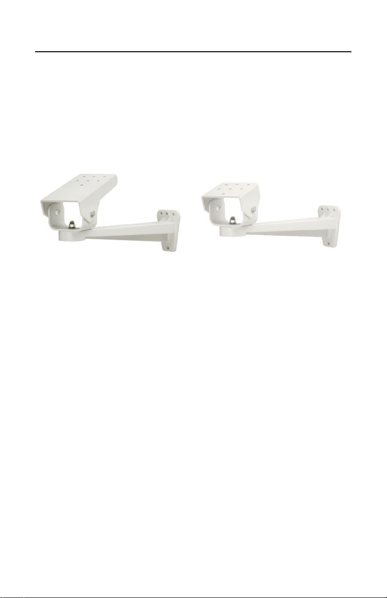
EM14
PARTS LIST
The following parts are supplied.
Qty Description
1 Mount, light duty wall
2 Screw, Hex head, 1/4-20 x 0.500-inch
2 Split washer, 1/4-inch
2 Flat washer, 3/16-inch
1 Installation manual
USER SUPPLIED PARTS LIST
The following installation parts and tools are needed but not supplied.
Qty Description
1 Enclosure, EH14, EH14-2, or EH14-3 (for EM14)
1 Enclosure, EH2508, EH2512, EH2515, EH3508, EH3512, or EH3515 (for EM1450)
1 Screwdriver for 1/4" hex head screws to attach the enclosure to the tilt table
2-4 Appropriate mounting fasteners depending on nature of mounting surface
1 Appropriate water-tight sealant, if installing the product outdoors
EM1450
4 C261M-E (8/14)
Page 5

Installing the Mount
1. Using the wall mount as a template, mark the holes for the mounting hardware on the mounting
surface.
WARNINGS:
• Make certain the mounting surface can support the full load of the mount,
enclosure, and camera.
• When installing the mount outdoors, seal the bolt holes with an appropriate
sealant to prevent water damage to the mounting surface. Apply the sealant
around the bolt holes between the mount and the mounting surface.
2. Prepare the surface.
3. Attach the mount to the mounting surface with the appropriate hardware (not supplied). If you
install the mount outdoors, apply a sealant between the mount and the mounting surface.
4. Attach the enclosure to the tilt table with the two 1/4-20 x 0.500-inch hex screws, split washers,
and flat washers (supplied).
5. Adjust the pan position of the mount:
a. Loosen the cap nut on the tilt table support bracket.
b. Adjust the pan position of the tilt table by moving it to the left or right.
c. Re-tighten the cap nut.
6. Adjust the tilt position of the mount:
a. Loosen the two bolts on the tilt table.
b. Move the tilt table up or down.
c. Re-tighten the bolts.
C261M-E (8/14) 5
Page 6

Specifications
MODEL
EM14 Light duty wall mount; for use with EH14, EH14-2, and EH14-3
EM1450 Light duty wall mount; for use with EH2508, EH2512, EH2515,
MECHANICAL
Suggested Mounting Method Secure to solid surface with 2-4 fasteners, minimum M6
Enclosure Mounting 2 each: 1/4-20 x 0.500-inch screws
Pan Adjustment 360°
Tilt Adjustment ±75° (up or down)
Locking Method
Pan 1/4-20 high crown cap nut
Tilt 2 each: 3/8-16 x 0.500-inch bolts
GENERAL
Construction
Mounting Arm Die-cast aluminum
Tilt Table and Support Bracket Aluminum
Finish Gray polyester powder coat
Maximum Load 9 kg (20 lb)
Unit Weight
EM14 0.97 kg (2.14 lb)
EM1450 0.91 kg (2.00 lb)
enclosures
EH3508, EH3512, and EH3515 enclosures
(1/4-inch) diameter recommended.
NOTE: VALUES IN PARENTHESES ARE INCHES; ALL OTHERS ARE CENTIMETERS.
3.81
(1.50)
0.87 (Ø 0.343),
1X
EM14
6.81
(2.68)
3.78
(1.49)
5.08
(2.00)
3.68
(1.45)
14.61
(5.75)
0.69 (Ø 0.272), 7X
8.81
(3.47)
7.19
(2.83)
13.49
(5.31)
2.54(1.00)
5.08
(2.00)
2.54 (1.00)
NOTE: VALUES IN PARENTHESES ARE INCHES; ALL OTHERS ARE CENTIMETERS.
28.50
27.20
(10.71)
(11.22)
0.713 (Ø 0.281),
3X
7.21
(2.84)
8.84
(3.48)
0.87 (Ø 0.343),
1X
EM1450
3.81
(1.50)
6.99
(2.75)
0.713 (Ø 0.281),
3X
8.84
7.26
(3.48)
(2.86)
3.18
(1.25)
0.69 (Ø 0.272), 7X
26.75
(10.53)
5.08
(2.00)
8.81
(3.47)
4.42
(1.73)
3.81
(1.50)
7.62
(3.00)
28.50
(11.22)
7.21
(2.84)
6 C261M-E (8/14)
13.51
(5.32)
Page 7

WARRANTY STATEMENT
For information about Pelco’s product warranty and thereto related information, refer to www.pelco.com/warranty.
This equipment contains electrical or electronic components that must be recycled properly to comply with Directive
2002/96/EC of the European Union regarding the disposal of waste electrical and electronic equipment (WEEE).
Contact your local dealer for procedures for recycling this equipment.
REVISION HISTORY
Manual # Date Comments
C261M 3/99 Original version.
C261M 3/00 Revised Figure 1 and installation step 4 per ECO 00-5634.
C261M-A 2/06 Revised to new format. Corrected measurements in dimension drawing.
C261M-B 1/08 Revised mounting head hole pattern per ECO 07-17992.
C261M-C 1/11 Updated the Important Safety Instructions and Warranty, revised the Installation and Specifi-
C261M-D 4/14 Updated template, metric/imperial dimensions, and supplied screw size.
C261M-E 8/14 Added EM14 Wall Mount.
Pelco, the Pelco logo, and other trademarks associated with Pelco products referred to in this publication are trademarks of Pelco, Inc. or its affiliates.
All other product names and services are the property of their respective companies. ONVIF and the ONVIF logo are trademarks of ONVIF Inc.
Product specifications and availability are subject to change without notice. © Copyright 2014, Pelco, Inc. All rights reserved.
cations sections, and applied current format.
Page 8

Pelco by Schneider Electric 3500 Pelco Way Clovis, California 93612-5699 United States
USA & Canada Tel (800) 289-9100 Fax (800) 289-9150
International Tel +1 (559) 292-1981 Fax +1 (559) 348-1120
www.pelco.com www.pelco.com/community
 Loading...