

Page 1
INSTALLATION
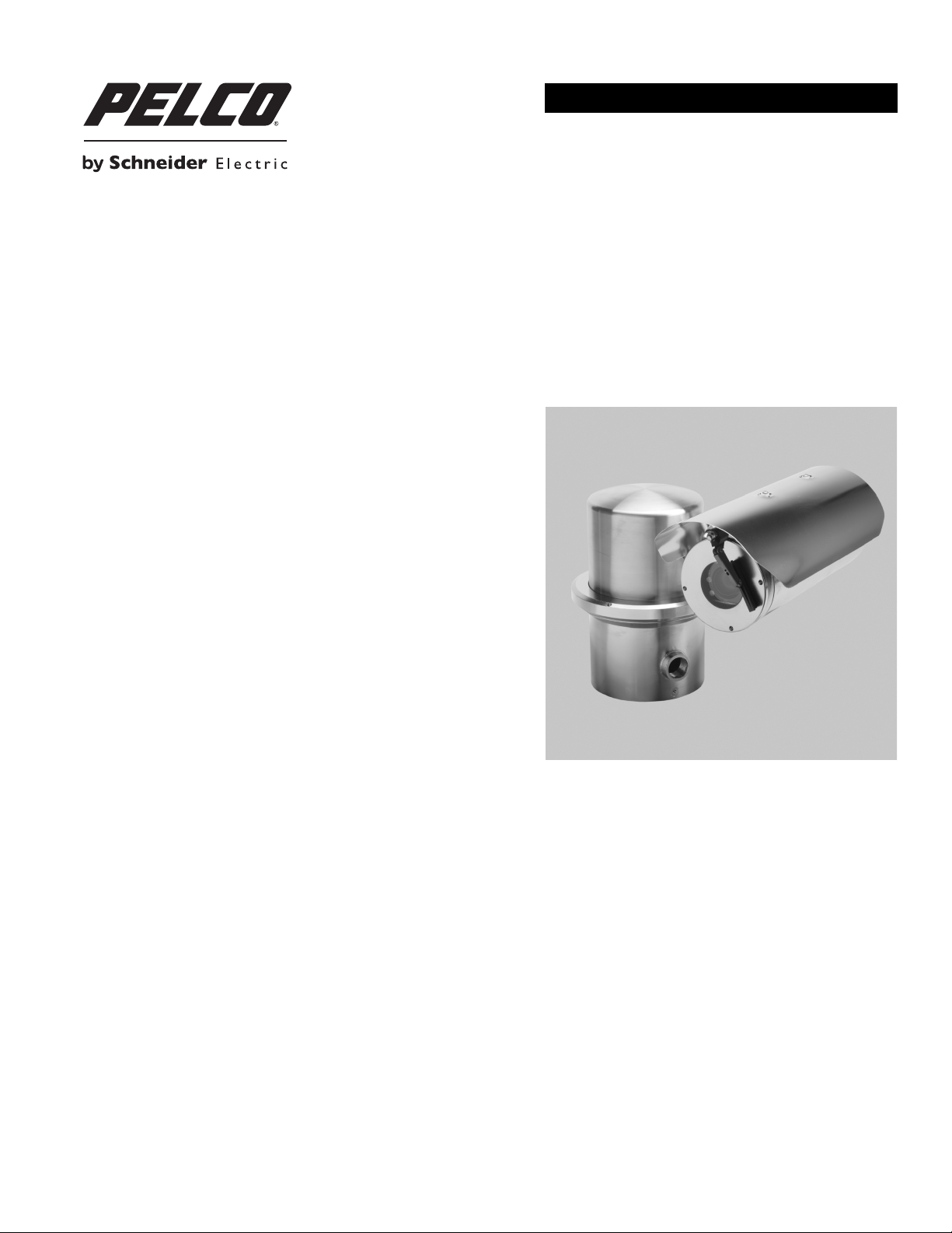
ExSite®/ExSite IP Series Explosionproof Fixed System
C1306M-F (11/12)
Page 2

Contents
SCHEDULE DOCUMENT
This document cannot be changed without prior regulatory review.
Important Safety Instructions . . . . . . . . . . . . . . . . . . . . . . . . . . . . . . . . . . . . . . . . . . . . . . . . . . . . . . . . . . . . . . . . . . . . . . . . . . . . . . . . . . . . . . . . . . . . 5
Description. . . . . . . . . . . . . . . . . . . . . . . . . . . . . . . . . . . . . . . . . . . . . . . . . . . . . . . . . . . . . . . . . . . . . . . . . . . . . . . . . . . . . . . . . . . . . . . . . . . . . . . . . . . 6
Parts List . . . . . . . . . . . . . . . . . . . . . . . . . . . . . . . . . . . . . . . . . . . . . . . . . . . . . . . . . . . . . . . . . . . . . . . . . . . . . . . . . . . . . . . . . . . . . . . . . . . . . . . . 6
User Supplied Parts List . . . . . . . . . . . . . . . . . . . . . . . . . . . . . . . . . . . . . . . . . . . . . . . . . . . . . . . . . . . . . . . . . . . . . . . . . . . . . . . . . . . . . . . . . . . . 6
Methods of Installation . . . . . . . . . . . . . . . . . . . . . . . . . . . . . . . . . . . . . . . . . . . . . . . . . . . . . . . . . . . . . . . . . . . . . . . . . . . . . . . . . . . . . . . . . . . . 7
Installing the Camera Module . . . . . . . . . . . . . . . . . . . . . . . . . . . . . . . . . . . . . . . . . . . . . . . . . . . . . . . . . . . . . . . . . . . . . . . . . . . . . . . . . . . . . . . . . . . . 8
Installing the Enclosure and Setting the Pan Position . . . . . . . . . . . . . . . . . . . . . . . . . . . . . . . . . . . . . . . . . . . . . . . . . . . . . . . . . . . . . . . . . . . . . . . . 11
Setting the Camera Module Tilt Angle . . . . . . . . . . . . . . . . . . . . . . . . . . . . . . . . . . . . . . . . . . . . . . . . . . . . . . . . . . . . . . . . . . . . . . . . . . . . . . . . . . . . 13
Installing the Sun Shroud . . . . . . . . . . . . . . . . . . . . . . . . . . . . . . . . . . . . . . . . . . . . . . . . . . . . . . . . . . . . . . . . . . . . . . . . . . . . . . . . . . . . . . . . . . . . . . 14
Maintenance . . . . . . . . . . . . . . . . . . . . . . . . . . . . . . . . . . . . . . . . . . . . . . . . . . . . . . . . . . . . . . . . . . . . . . . . . . . . . . . . . . . . . . . . . . . . . . . . . . . . . . . . 15
Camera Module Replacement . . . . . . . . . . . . . . . . . . . . . . . . . . . . . . . . . . . . . . . . . . . . . . . . . . . . . . . . . . . . . . . . . . . . . . . . . . . . . . . . . . . . . . 15
Specifications . . . . . . . . . . . . . . . . . . . . . . . . . . . . . . . . . . . . . . . . . . . . . . . . . . . . . . . . . . . . . . . . . . . . . . . . . . . . . . . . . . . . . . . . . . . . . . . . . . . . . . . 19
FIXED System. . . . . . . . . . . . . . . . . . . . . . . . . . . . . . . . . . . . . . . . . . . . . . . . . . . . . . . . . . . . . . . . . . . . . . . . . . . . . . . . . . . . . . . . . . . . . . . .6
Models with a Wiper. . . . . . . . . . . . . . . . . . . . . . . . . . . . . . . . . . . . . . . . . . . . . . . . . . . . . . . . . . . . . . . . . . . . . . . . . . . . . . . . . . . . . . . . . .6
C1306M-F (11/12) 3
Page 3

List of Illustrations
1 Standard and Inverted Installations . . . . . . . . . . . . . . . . . . . . . . . . . . . . . . . . . . . . . . . . . . . . . . . . . . . . . . . . . . . . . . . . . . . . . . . . . . . . . . . . . . . 7
2 Loosen the Setscrew . . . . . . . . . . . . . . . . . . . . . . . . . . . . . . . . . . . . . . . . . . . . . . . . . . . . . . . . . . . . . . . . . . . . . . . . . . . . . . . . . . . . . . . . . . . . . . 8
3 Remove the Back Cap of the Enclosure . . . . . . . . . . . . . . . . . . . . . . . . . . . . . . . . . . . . . . . . . . . . . . . . . . . . . . . . . . . . . . . . . . . . . . . . . . . . . . . . 8
4 Install the Camera Module . . . . . . . . . . . . . . . . . . . . . . . . . . . . . . . . . . . . . . . . . . . . . . . . . . . . . . . . . . . . . . . . . . . . . . . . . . . . . . . . . . . . . . . . . . 9
5 Center the Wiper Blade . . . . . . . . . . . . . . . . . . . . . . . . . . . . . . . . . . . . . . . . . . . . . . . . . . . . . . . . . . . . . . . . . . . . . . . . . . . . . . . . . . . . . . . . . . . . 9
6 Install the Wiper Arm . . . . . . . . . . . . . . . . . . . . . . . . . . . . . . . . . . . . . . . . . . . . . . . . . . . . . . . . . . . . . . . . . . . . . . . . . . . . . . . . . . . . . . . . . . . . . 10
7 Factory-Installed Power Module Seal . . . . . . . . . . . . . . . . . . . . . . . . . . . . . . . . . . . . . . . . . . . . . . . . . . . . . . . . . . . . . . . . . . . . . . . . . . . . . . . . 11
8 Attach the Enclosure Unit to the Power Module . . . . . . . . . . . . . . . . . . . . . . . . . . . . . . . . . . . . . . . . . . . . . . . . . . . . . . . . . . . . . . . . . . . . . . . . 11
9 Set the Tilt Position. . . . . . . . . . . . . . . . . . . . . . . . . . . . . . . . . . . . . . . . . . . . . . . . . . . . . . . . . . . . . . . . . . . . . . . . . . . . . . . . . . . . . . . . . . . . . . . 13
10 Install the Sun Shroud . . . . . . . . . . . . . . . . . . . . . . . . . . . . . . . . . . . . . . . . . . . . . . . . . . . . . . . . . . . . . . . . . . . . . . . . . . . . . . . . . . . . . . . . . . . . 14
11 Remove the Back Cap of the Camera Enclosure . . . . . . . . . . . . . . . . . . . . . . . . . . . . . . . . . . . . . . . . . . . . . . . . . . . . . . . . . . . . . . . . . . . . . . . . 15
12 Remove/Install the Camera Module. . . . . . . . . . . . . . . . . . . . . . . . . . . . . . . . . . . . . . . . . . . . . . . . . . . . . . . . . . . . . . . . . . . . . . . . . . . . . . . . . . 16
13 Install the Camera Module . . . . . . . . . . . . . . . . . . . . . . . . . . . . . . . . . . . . . . . . . . . . . . . . . . . . . . . . . . . . . . . . . . . . . . . . . . . . . . . . . . . . . . . . . 17
14 Center the Wiper Blade . . . . . . . . . . . . . . . . . . . . . . . . . . . . . . . . . . . . . . . . . . . . . . . . . . . . . . . . . . . . . . . . . . . . . . . . . . . . . . . . . . . . . . . . . . . 17
4 C1306M-F (11/12)
Page 4

Important Safety Instructions
CAUTION:
RISK OF ELECTRIC SHOCK.
DO NOT OPEN.
1. Read these instructions.
2. Keep these instructions.
3. Heed all warnings.
4. Follow all instructions.
5. Do not block any ventilation openings. Install in accordance with the manufacturer’s instructions.
6. To reduce the risk of ignition of hazardous atmospheres, disconnect the equipment from the supply circuit before opening. Keep assembly
tightly closed when in operation.
7. The maximum ambient temperature range is –76° to 140°F (–60° to 60°C).
8. Only use attachments/accessories specified by the manufacturer.
9. Refer all servicing to qualified service personnel. Servicing is required when the apparatus has been damaged in any way, such as powersupply cord or plug is damaged, liquid has been spilled or objects have fallen into the apparatus, the apparatus has been exposed to rain or
moisture, does not operate normally, or has been dropped.
10. Installation should be done only by qualified personnel and conform to all local codes.
11. Unless the unit is specifically marked as a NEMA Type 3, 3R, 3S, 4, 4X, 6, or 6P enclosure, it is designed for indoor use only and it must not
be installed where exposed to rain and moisture.
12. Use only installation methods and materials capable of supporting four times the maximum specified load.
13. Use stainless steel hardware to fasten the mount to outdoor surfaces.
14. AN ALL-POLE MAINS SWITCH with a contact separation of at least 3 mm in each pole shall be incorporated in the electrical ins tallation of
the building.
15. A readily accessible disconnect device shall be incorporated in the building installation wiring.
16. CAUTION: These servicing instructions are for use by qualified service personnel only. To reduce the risk of electric shock do not perform
any servicing other that contained in the operating instructions unless you are qualified to do so.
17. Only use replacement parts recommended by Pelco.
18. A certified flameproof, “d,” sealing device such as a stopping box with setting compound shall be provided, either in the flameproof
enclosure or immediately at the entrance thereto.
19. For ambient temperatures below 14°F (–10°C) use field wiring suitable for both minimum and maximum ambient temperature.
The product and/or manual may bear the following marks:
WARNING: This symbol indicates that dangerous voltage constituting a risk of electric shock
is present within this unit.
This symbol indicates that there are important operating and maintenance instructions in the
literature accompanying this unit.
WARNING: HAZARDOUS MOVING PARTS. KEEP FINGERS AND OTHER BODY PARTS AWAY.
WARNING: To reduce the risk of ignition of hazardous atmospheres, disconnect the
equipment from the supply circuit before opening. Keep assembly tightly closed when
operating.
C1306M-F (11/12) 5
WARNING: To reduce the risk of ignition of hazardous atmospheres, conduit runs must have a
sealing fitting connected within 2 inches of the enclosure.
TO REDUCE THE RISK OF IGNITION DO NOT OPEN WHEN AN EXPLOSIVE GAS ATMOSPHERE
MAY BE PRESENT.
Page 5

Description
ExSite®/ExSite IP Series systems are designed to meet the rigorous requirements of explosionproof and dust-ignitionproof electrical equipment
for installation and use in hazardous locations. The system can be installed in a standard or inverted position and features manually adjustable
200 degrees of pan and 180 degrees of tilt positioning.
The ExSite IP Series system has all of the features and functionality of the analog ExSite Series and includes a built-in 100Base-TX network
interface for live streaming using a standard Web browser.
Both analog and network systems are available with a choice of power module: input voltage of 24 VAC or 100 to 240 VAC.
This manual includes instructions for installing the camera and pan/tilt.
WARNING: Install the ExSite/ExSite IP Series power module before you install the camera and fixed pan/tilt. For instructions on how to
install the power module, refer to the manual included with the power module.
Once the system installation is complete, refer to the operation manual available on the resource disc for instructions on how to operate and your
system.
PARTS LIST
FIXED SYSTEM
Qty Description
1 Enclosure (with or without wiper)
1 Camera module
1 Sun shroud
1 Sun shroud hardware pack
2 Screws, 6-32 Phillips, pan head
2Nylon washers
1 Spanner wrench
2 Allen wrench, 1.5 mm
2 Allen wrench, 2 mm
MODELS WITH A WIPER
Qty Description
1 Wiper arm
1 Green bushing
1 Screw, 8-32 Phillips, flat head
USER SUPPLIED PARTS LIST
The following tools are needed but not supplied:
Qty Description
1 21 mm wrench
1 41 mm wrench
6 C1306M-F (11/12)
Page 6
METHODS OF INSTALLATION
The system can be installed in a standard or inverted position. When installed for inverted operation, the camera orientation and control
functions are reconfigured for normal operation through the system’s software. Hardware adjustment is not required for inverted operation.
WARNINGS:
• The total weight of the system is 15.71 kg (34.70 lb). Use caution when lifting and assembling the enclosure component on the power
module. It is recommended that non-slip gloves be worn during installation.
• Do not turn the body of the enclosure more than 200 degrees in either direction or damage to the power module cable may occur.
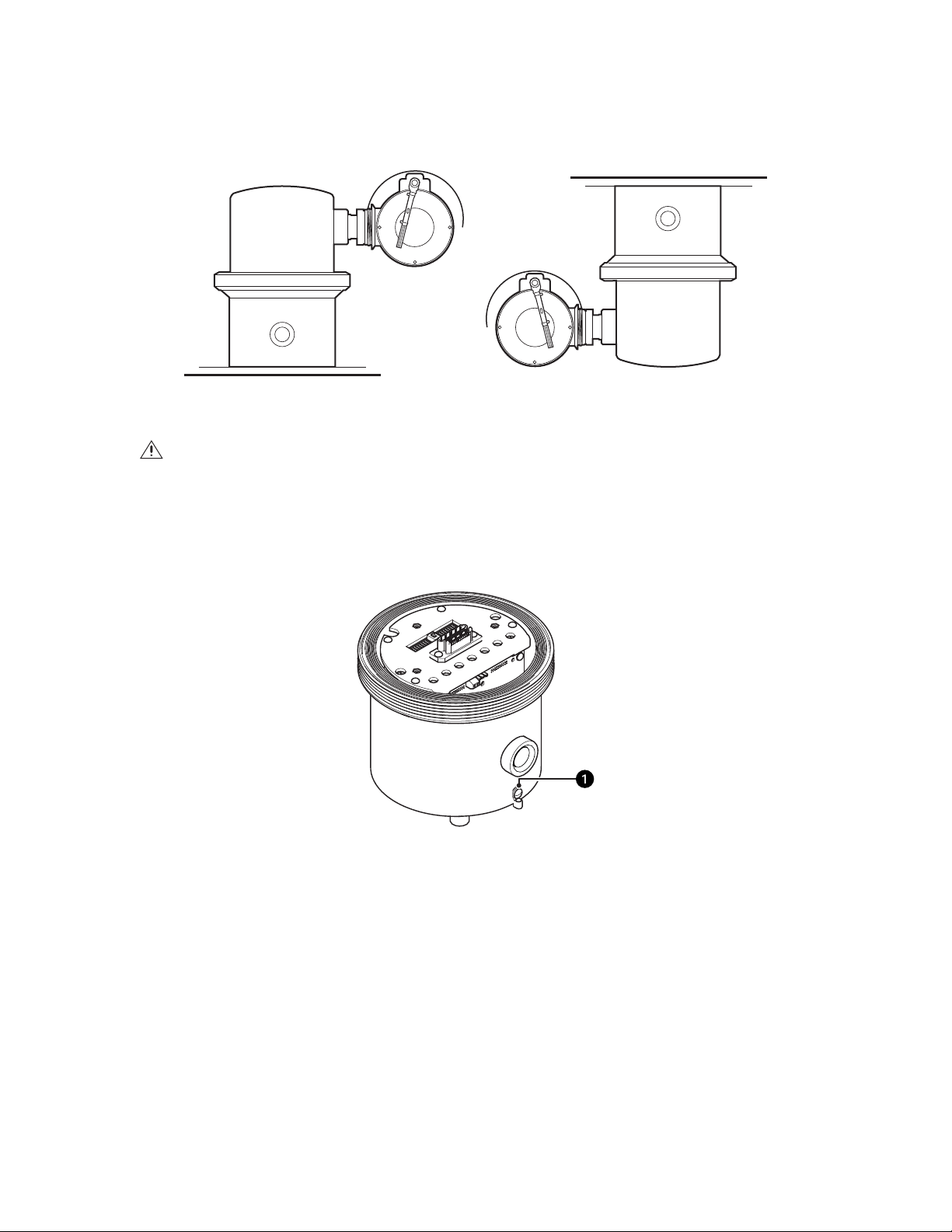
Figure 1. Standard and Inverted Installations
During installation, it is important to attach a 10 AWG copper stranded wire (minimum requirement) from the earth ground attachment point on
the unit to an appropriate grounding location for your installation.
Figure 2. Attach an Earth Ground
ì
Earth Ground Attachment Point
C1306M-F (11/12) 7
Page 7
Installing the Camera Module
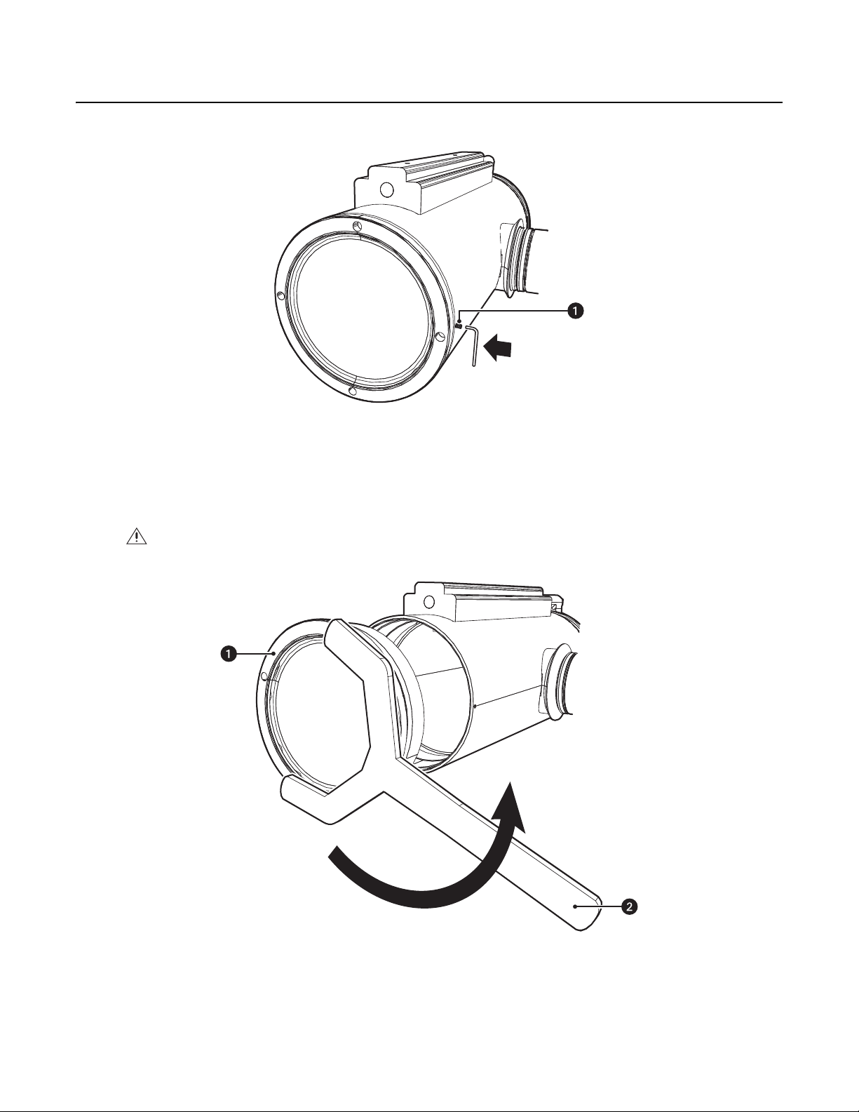
1. Loosen the setscrew at the back of the enclosure with the 1.5 mm Allen wrench (supplied).
Figure 3. Loosen the Setscrew
2. Use the spanner wrench (supplied) to loosen the back of the camera enclosure (refer to Figure 4). Once the back is loose, use your hands to
continue to loosen it until it can be removed.
ì
Setscrew
WARNING: To avoid thread damage, carefully remove the back of the camera enclosure. Never use force to remove the back of the
camera enclosure.
Figure 4. Re move the Back Cap of the Enclosure
ì
Back Cap of Enclosure
î
Spanner Wrench
8 C1306M-F (11/12)
Page 8

3. Slide the camera module into the enclosure. Refer to Figure 5 to position the camera module properly in the enclosure.
(Models with a wiper) The tab located inside the enclosure must be pointing down before installing the camera module (refer to Figure 5).
To position the tab, place the wiper blade (located at the front of the enclosure) in the center of the viewing window (refer to Figure 6).
WARNING: Do not force the camera module into the enclosure.
4. Carefully mate the camera’s power connector to the mating connector located inside the enclosure.
Figure 5. Install the Camera Module
ì
Camera Module
î
Center Notches
Figure 6. Center the Wiper Blade
ì
ï
ñ
Wiper Blade
Enclosure Tab
Camera Enclosure
C1306M-F (11/12) 9
Page 9

5. Install the wiper arm (refer to Figure 7).
a. Place the green bushing (supplied with wiper models). on the stud located behind the handle of the camera module. The bushing
should be in the same orientation as shown in Figure 7.
b. Place the ridge of the wiper arm in the notch of the enclosure tab, and then place the slot of the wiper arm over the green bushing.
6. Secure the wiper arm with the 8-32 Phillips flat head screw (supplied with wiper models).
Figure 7. Install the Wiper Arm
ì
Enclosure Tab
î
8-32 Phillips Flat Head Screw
ï
Wiper Arm
ñ
Camera Module Handle
ó
Green Bushing
r
Stud
WARNINGS:
• To avoid thread damage, carefully install the back cap on the enclosure.
• Never force the back cap onto the end of the enclosure.
• When installation is completed, there should be no gap between the back cap and the enclosure.
7. Reinstall the back cap on the enclosure:
a. Using your hands, turn the back cap clockwise until you can no longer turn it. The back cap should turn easily until it comes in contact
with the O-ring. If it does not turn easily, the threads are not aligned and thread damage will occur.
b. Continue tightening the back cap with the spanner wrench (supplied). There should be no gap between the back cap and the enclosure
when the back cap is tightened and properly installed.
c. Once the back cap is installed, secure the back cap with the setscrew using the 1.5 mm Allen wrench (supplied).
10 C1306M-F (11/12)
Page 10

Installing the Enclosure and Setting the Pan Position
1. Verify that the power module seal is properly seated in the groove on the top of the power module.
Figure 8. Factory-Installed Power Module Seal
ì
Power Module Seal
î
Power Module
WARNING: Use caution when attaching the enclosure unit to the power module. If the grooves on the top of the power module are
damaged, the integrity of the unit could be compromised.
2. Attach the enclosure unit to the power module.
a. Align the pins on the enclosure unit with the holes on the power module.
b. Carefully mate the enclosure connector to the power module connector.
Figure 9. Attach the Enclosure Unit to the Power Module
ì
Locking Ring
î
Pins
ï
Holes
C1306M-F (11/12) 11
Page 11

WARNINGS:
• Total weight of the pan/tilt component is 15.71 kg (34.70 lb). Use caution when lifting and assembling the pan/tilt component on the
power module.
• It is recommended that non-slip gloves be worn during installation.
• Avoid thread damage. Never use force when assembling and tightening the threaded components of the system.
3. Turn the body of the enclosure to the left or right to set the pan position of the unit.
WARNING: Do not turn the body of the enclosure more than 200 degrees in either direction or damage to the internal power module cable
may occur.
4. Using your hands, carefully thread the enclosure locking ring onto the threads of the power module until the threads are completely
engaged.
5. Use the spanner wrench (supplied) to tighten the locking ring and fix the position of the enclosure.
6. Tap the spanner wrench handle with a hammer or the palm of your hand to ensure a secure fit.
7. Tighten the locking ring setscrew with the 2 mm Allen wrench (supplied) to secure it. Make sure that the pan position is maintained when
tightening the locking ring.
12 C1306M-F (11/12)
Page 12

Setting the Camera Module Tilt Angle
1. Loosen the setscrew locking nut with the 2 mm Allen wrench (supplied).
2. Place a 41 mm open end or crescent wrench (not supplied) on the tilt locking nut and a 21 mm open end wrench (not supplied) on the tilt
shaft.
Figure 10. Set the Tilt Position
ì
Setscrew
î
Tilt Lock Nut
ï
Tilt Shaft
3. Hold the tilt shaft in position with the 21 mm wrench (not supplied), and then turn the 41 mm wrench (not supplied) to loosen the tilt
locking nut.
4. Adjust the tilt position of the camera module by moving the camera module up or down.
5. Continue to hold the tilt shaft with the 21 mm wrench (not supplied) and then tighten the tilt locking nut to set the tilt position of the camera
module.
NOTE: Make sure the tilt position is maintained when tightening the locking ring.
6. Tighten the setscrew locking nut with the 2 mm Allen wrench (supplied) to secure it.
C1306M-F (11/12) 13
Page 13

Installing the Sun Shroud
1. Align the mounting holes on the sun shroud with the holes on top of the enclosure.
2. Insert the nylon washers (supplied with sun shroud hardware pack) and the 6-32 Phillips pan head screws (supplied with sun shroud
hardware pack) into the mounting holes (refer to Figure 11).
3. Tighten the screws to secure the sun shroud to the enclosure.
Figure 11. Install the Sun Shroud
ì
Sun Shroud
î
Nylon Washers
ï
6-32 Phillips Pan Head Screws
14 C1306M-F (11/12)
Page 14

Maintenance
CAMERA MODULE REPLACEMENT
WARNING: To reduce the risk of ignition of hazardous atmospheres, disconnect the equipment from the power supply before opening.
Keep the assembly tightly closed when operating.
To replace the camera module:
1. Remove the back cap of the camera enclosure (refer to Figure 12).
a. Loosen the setscrew with a 1.5 mm Allen wrench (supplied).
b. Use the spanner wrench (supplied) to loosen the back cap of the camera enclosure. Once the back cap is loose, use your hands to
continue to loosen it until it can be removed.
Figure 12. Remove the Back Cap of the Camera Enclosure
ì
Back Cap of Enclosure
î
Spanner Wrench
ï
Setscrew
C1306M-F (11/12) 15
Page 15

2. (Models with a wiper) Remove the 8-32 Phillips flat head screw (supplied with wiper models) that secures the wiper inside the enclosure.
3. (Models with a wiper) Remove the wiper arm and the green bushing (supplied with wiper models) from the unit.
4. Slide the camera module out of the enclosure.
Figure 13. Remove/Install the Camera Module
ì
Enclosure Tab
î
8-32 Phillips Flat Head Screw
ï
Wiper Arm
ñ
Camera Module Handle
ó
Green Bushing
r
Stud
16 C1306M-F (11/12)
Page 16

5. Slide the replacement camera module into the enclosure (refer to Figure 14).
WARNING: Never force the camera module into the enclosure.
(Models with a wiper) The tab located inside the enclosure must be pointing down before installing the camera module (refer to Figure 14).
To position the tab, place the wiper blade (located at the front of the enclosure) in the center of the viewing window (refer to Figure 15).
6. Carefully mate the camera’s power connector to the mating connector located inside the enclosure.
Figure 14. Install the Camera Module
ì
Camera ModuleïEnclosure Tab
î
Center NotchesñCamera Enclosure
Figure 15. Center the Wiper Blade
ì
Wiper Blade
C1306M-F (11/12) 17
Page 17

7. (Models with a Wiper) Reinstall the wiper arm (refer to Figure 12 on page 15).
a. Reinstall the green bushing on the stud located behind the handle of the camera module.
b. Place the ridge of the wiper arm in the notch of the enclosure tab, and then place the slot of the wiper arm over the green bushing.
8. Secure the wiper arm with the 8-32 Phillips flat head screw (refer to Figure 13 on page 16).
WARNINGS:
• To avoid thread damage, carefully install the back cap on the enclosure.
• Never force the back cap onto the end of the enclosure.
• When installation is completed, there should be no gap between the back cap and the enclosure.
9. Reinstall the back cap on the enclosure:
a. Using your hands, turn the back cap clockwise until you can no longer turn it. The back cap should turn easily until it comes in contact
with the O-ring. If it does not turn easily, the threads are not aligned and thread damage will occur.
b. Continue tightening the back cap with the spanner wrench (supplied). There should be no gap between the back cap and the enclosure
when the back cap is tightened and properly installed.
c. After the back cap is installed, secure the back cap with the setscrew using a 1.5 mm Allen wrench (supplied).
18 C1306M-F (11/12)
Page 18

Specifications
ELECTRICAL
Input Voltage 24 VAC or 100 to 240 VAC, 50/60 Hz
Input Voltage Range ±10%
Power Consumption Maximum 60 W (120 VA) per system
Heater and Defroster Microprocessor controlled
Electrical Connections 6-foot wire harness with connections for power, video, data control, alarm inputs, and auxiliary outputs
MECHANICAL
Cable Entry One 1.91 cm (0.75-inch) NPT threaded opening
GENERAL
Construction 316L stainless steel
Finish Electropolish
Viewing Window 12.7 mm (0.50-inch) thick, soda-lime tempered glass
Operating Temperature –60° to 60°C (–76° to 140°F)
Unit Weight 11.33 kg (34.70 lb)
Effective Projected Area (EPA) 31.1 square inches
NOTE: Please contact Pelco for information on the dimensions of the flameproof joints.
NOTE: VALUES IN PARENTHESES ARE INCHES; ALL OTHERS ARE CENTIMETERS.
33.27 (13.1)
4 PLCS. TYP.
10MM - 1.5MM X 14MM
ON A 4.75-INCH DIA. B.C.
EQUALLY SPACED
13.03
(5.13)
12.47
(4.91)
1.91 NPT
(0.75)
29.21 (11.5)
8.52
(3.354)
26.8
(10.5)
C1306M-F (11/12) 19
Page 19

CAMERA/OPTICS
Signal Format NTSC, PAL
Scanning System 2:1 Interlace
Image Sensor 1/4-inch progressive scan CCD
Effective Pixels
NTSC 768 (H) x 494 (V)
PAL 752 (H) x 582 (V)
Horizontal Resolution
NTSC 540 TV lines
PAL 540 TV lines
Lens f/1.4 (focal length, 3.3 ~ 119 mm optical)
Zoom 36X optical, 12X digital
Zoom Speed 2.9/4.2/5.8 seconds
Horizontal Angle of View 57.2° at 3.3 mm wide zoom
1.7° at 119 mm telephoto zoom
Focus Automatic with manual override
Maximum Sensitivity at 35 IRE
NTSC 0.018 lux at 1/2 sec shutter (color)
0.55 lux at 1/60 sec shutter (B-W)
0.00018 lux at 1/2 sec shutter (B-W)
PAL 0.015 lux at 1/1.5 sec shutter (color)
0.45 lux at 1/50 sec shutter (B-W)
0.00015 lux at 1/1.5 sec shutter (B-W)
Sync System Internal/AC line lock, phase adjustable using remote control, V-Sync*
White Balance Automatic with manual override*
Shutter Speed Automatic (electronic iris)/Manual
NTSC 1/2 ~ 1/30,000*
PAL 1/1.5 ~ 1/30,000*
Iris Control Automatic Iris Control with manual override*
Gain Control Automatic/OFF*
Video Output 1 Vp-p, 75 ohms
Video Signal to Noise >50 dB
*(Analog Models only) Manual control of camera setup functions can be done with CM6700, CM6800, CM8500, CM9500, CM9740, CM9760,
CM9770, CM9780, KBD200A, KBD300A, and MPT9500 controllers. It cannot be done with CM7500, MPT9000, or KBD9000 controllers.
20 C1306M-F (11/12)
Page 20

VIDEO (ExSite IP Models Only)
Video Encoding H.264 base profile, MPEG-4, and MJPEG
Video Streams Up to 2 simultaneous streams; the second stream is variable based on the setup of the primary stream
Frame Rate Up to 30, 25, 24, 15, 12.5, 12, 10, 8, 7. 5, 6, 5, 4, 3, 2.5, 2, 1
(dependent upon coding, resolution, and stream configuration)
Available Resolutions
Resolution
Width Height Format
704 480 NTSC 30 ips 5.4 Mbps 30 ips 1.9 Mbps 30 ips 2.0 Mbps
352 240 NTSC 30 ips 1.3 Mbps 30 ips 0.5 Mbps 30 ips 0.6 Mbps
704 576 PAL 25 ips 5.4 Mbps 25 ips 1.9 Mbps 25 ips 2.0 Mbps
Supported Protocols TCP/IP, UDP/IP (Unicast, Multicast IGMP), UPnP, DNS, DHCP, RTP, RTSP, NTP, IPv4, SNMP, QOS, HTTP,
HTTPS, LDAP (client), SSH, SSL, SMTP, FTP, mDNS (Bonjour
MJPEG H.264 Base Profile MPEG-4
Maximum
IPS
Recommended
Bit Rate
Maximum
IPS
®
), and 802.1x (EAP)
Recommended
Bit Rate
Maximum
IPS
Recommended
Bit Rate
Users
Unicast Up to 20 simultaneous users depending on resolution settings (2 guaranteed streams)
Multicast Unlimited users H.264 or MPEG-4
Security Access Password protected
Software Interface Web browser view and setup, up to 16 cameras
Pelco System Integration Endura
®
1.5 or later (MPEG-4) or Endura 2.0 or later (H.264); Digital Sentry® 4.2 IP bundle 3 or later;
DX8100 Series 2.0 or later; and DVR5100 version 1.5.4 or later
Open IP Integration Pelco IP camera API
Minimum System Requirements
Processor Intel
®
Pentium® 4 microprocessor, 1.6 GHz
Operating System Microsoft® Windows® XP, Windows Vista®, Windows 7® or Mac® OS X 10.4 (or later)
Memory 512 MB RAM
Network Interface Card 100 megabits (or greater)
Monitor Minimum of 1024 x 768 resolution, 16- or 32-bit pixel color resolution
Web Browser* Internet Explorer® 7.0 (or later) or Mozilla® Firefox® 3.0 (or later)
Media Player
†
Pelco Media Player or QuickTime® 7.6.5 for Windows XP, Windows Vista, or
QuickTime 7.6.4 for Mac OS X 10.4
*Internet Explorer is not supported by Mac OS X 10.4.
†
This product is not compatible with QuickTime version 7.6.4 for Windows XP or Windows Vista. If you have this version installed on your PC, you
will need to upgrade to QuickTime version 7.6.5.
C1306M-F (11/12) 21
Page 21

CERTIFICATIONS/RATINGS
•FCC
• UL/cUL Listed
• UL/cUL Hazardous Locations Listed per NEC Division and Zone requirement
Class I, Groups A, B, C, and D
Class II, Groups E, F, G, T5
Class I, Zone 1, AEx d IIC
• AEx tD 21 T105°C
• BR-Ex d IIC, T5, IP66
04/UL-BRAE-0027
• IECEx UL 11.0007X
• Ex d IIC T5 Gd
• Ex tb IIIC T105°C Db IP66
• DEMKO 04 ATEX 0413858X
0539 II 2 G Ex d IIC, T5 Gb
II 2 D Ex tb IIIC T105°C Db IP66
• Tamb –60°C to 60°C
• NEPSI-China, Ex d IIC, T5, Cert No. GYJ05584
•C-Tick
• S Mark for Argentina
• Meets NEMA Type 4X standards
• ONVIF 1.02*
• Lloyd’s Register Type Approval: Marine, offshore, and industrial installations for use in environmental categories ENV1, ENV2, and ENV5;
Certificate No. 06/60001
†
*Applies to IP models only.
†
Applies to analog models only.
22 C1306M-F (11/12)
Page 22

PRODUCT WARRANTY AND RETURN INFORMATION
WARRANTY
Pelco will repair or replace, without charge, any merchandise proved defective in
material or workmanship for a period of one year after the date of shipment.
Exceptions to this warranty are as noted below:
• Five years:
– Fiber optic products
– Unshielded Twisted Pair (UTP) transmission products
– CC3701H-2, CC3701H-2X, CC3751H-2, CC3651H-2X, MC3651H-2, and
MC3651H-2X camera models
• Three years:
– FD Series and BU Series analog camera models
– Fixed network cameras and network dome cameras with Sarix
– Sarix thermal imaging products (TI and ESTI Series)
– Fixed analog camera models (C20 Series, CCC1390H Series, C10DN Series,
and C10CH Series)
– EH1500 Series enclosures
– Spectra
– Spectra HD dome products
– Camclosure
®
IV products (including Spectra IV IP)
®
IS Series integrated camera systems
– DX Series video recorders (except DX9000 Series which is covered for a
period of one year), DVR5100 Series digital video recorders, Digital Sentry
Series hardware products, DVX Series digital video recorders, and NVR300
Series network video recorders
®
– Endura
– Genex
Series distributed network-based video products
®
Series products (multiplexers, server, and keyboard)
– PMCL200/300/400 Series LCD monitors
– PMCL5xxF Series and PMCL5xxNB Series LCD monitors
– PMCL5xxxBL Series LED monitors
• Two years:
– Standard varifocal, fixed focal, and motorized zoom lenses
– DF5/DF8 Series fixed dome products
®
– Legacy
– Spectra III
Series integrated positioning systems
™
, Spectra Mini, Spectra Mini IP, Esprit®, ExSite®, ExSite IP, and
PS20 scanners, including when used in continuous motion applications
– Esprit Ti and TI2500 Series thermal imaging products
– Esprit and WW5700 Series window wiper (excluding wiper blades)
– CM6700/CM6800/CM9700 Series matrix
– Digital Light Processing (DLP
®
) displays (except lamp and color wheel). The
lamp and color wheel will be covered for a period of 90 days. The air filter is
not covered under warranty.
®
technology
•Six months:
– All pan and tilts, scanners, or preset lenses used in continuous motion
applications (preset scan, tour, and auto scan modes)
Pelco will warrant all replacement parts and repairs for 90 days from the date of
Pelco shipment. All goods requiring warranty repair shall be sent freight prepaid
to a Pelco designated location. Repairs made necessary by reason of misuse,
alteration, normal wear, or accident are not covered under this warranty.
Pelco assumes no risk and shall be subject to no liability for damages or loss
resulting from the specific use or application made of the Products. Pelco’s liability
for any claim, whether based on breach of contract, negligence, infringement of
any rights of any party or product liability, relating to the Products shall not exceed
the price paid by the Dealer to Pelco for such Products. In no event will Pelco be
liable for any special, incidental, or consequential damages (including loss of use,
loss of profit, and claims of third parties) however caused, whether by the
negligence of Pelco or otherwise.
The above warranty provides the Dealer with specific legal rights. The Dealer may
also have additional rights, which are subject to variation from state to state.
If a warranty repair is required, the Dealer must contact Pelco at (800) 289-9100 or
(559) 292-1981 to obtain a Repair Authorization number (RA), and provide the
®
following information:
1. Model and serial number
2. Date of shipment, P.O. number, sales order number, or Pelco invoice number
3. Details of the defect or problem
If there is a dispute regarding the warranty of a product that does not fall under
the warranty conditions stated above, please include a written explanation with
the product when returned.
Method of return shipment shall be the same or equal to the method by which the
item was received by Pelco.
RETURNS
To expedite parts returned for repair or credit, please call Pelco at (800) 289-9100
or (559) 292-1981 to obtain an authorization number (CA number if returned for
credit, and RA number if returned for repair) and designated return location.
All merchandise returned for credit may be subject to a 20 percent restocking and
refurbishing charge.
Goods returned for repair or credit should be clearly identified with the assigned
CA or RA number and freight should be prepaid.
Revised 10-9-12
The materials used in the manufacture of this document and its components are compliant to the requirements of Directive 2002/95/EC.
This equipment contains electrical or electronic components that must be recycled properly to comply with Directive 2002/96/EC of the European Union
regarding the disposal of waste electrical and electronic equipment (WEEE). Contact your local dealer for procedures for recycling this equipment.
REVISION HISTORY
Manual # Date Comments
C1306M 8/05 Original version.
C1306M-A 7/06 Updated for the new factory-installed power module seal (ECO 06-1400). Revised power module installation instructions. Removed Figure 9.
C1306M-B 10/06 Removed color reference to power module seal (ECO 06-14300). Added power module warning. Added Figure 9.
C1306M-C 11/08 Changed camera specs per CN22046.
C1306M-D 7/09 Updated Important Safety Instructions section and added product certifications; UL certification requirement. Reference CN22827.
C1306M-E 2/11 Updated manual for ExSite IP release. Removed power module installation information. Created separate power module installation manuals: one for ExSite analog
C1306M-F 11/12 Updated manual to include UL regulatory review note for ATEX compliant products.
Pelco, the Pelco logo, and other trademarks associa ted with Pelco products referred to in this publication are trademarks of Pelco, Inc. or its affilia tes. © Copyright 2012, Pelco, Inc.
ONVIF and the ONVIF logo are trademarks of ONVIF Inc. All other product names and services are the property of their respective companies. All rights reserved.
Product specifications and availability are subject to change without notice.
models and one for ExSite IP models.
Page 23

Pelco by Schneider Electric 3500 Pelco Way Clovis, California 93612-5699 United States
USA & Canada Tel (800) 289-9100 Fax (800) 289-9150
International Tel +1 (559) 292-1981 Fax +1 (559) 348-1120
www.pelco.com www.pelco.com/community
 Loading...