

Page 1
®
EH8000 Series
Pressurized
Camera
Enclosures
Installation/
Operation Manual
C418M (8/97)
Pelco • 300 W. Pontiac Way, Clovis, CA 93612-5699 • USA • (800) 289-9100 or (1-559) 292-1981
FAX (800) 289-9150 or (1-559) 292-3827 • DataFAX (800) 289-9108 or (1-559) 292-0435
International Customers call (1-559) 292-1981 or FAX (1-559) 348-1120
Page 2

TABLE OF CONTENTS
Section Page
1.0 SCOPE.............................................................................................................................................. 1
1.1 WARNINGS............................................................................................................................. 1
2.0 DESCRIPTION.................................................................................................................................. 1
2.1 MODEL NUMBERS ................................................................................................................. 2
2.2 OPTIONAL ACCESSORIES.................................................................................................... 2
2.3 RECOMMENDED MOUNTS ................................................................................................... 2
2.4 RECOMMENDED CONTROLS............................................................................................... 2
3.0 SPECIFICATIONS............................................................................................................................. 3
4.0 INSTALLATION ................................................................................................................................. 4
4.1 ENCLOSURE MOUNTING — FIXED...................................................................................... 4
4.2 ENCLOSURE MOUNTING — PAN/TILT................................................................................. 5
4.3 CAMERA/LENS INSTALLATION AND ADJUSTMENTS ......................................................... 6
4.4 MATING CONNECTOR ASSEMBLY....................................................................................... 6
4.5 SUN SHROUD INSTALLATION ............................................................................................ 10
5.0 OPERATION ................................................................................................................................... 10
5.1 SYSTEM TEST...................................................................................................................... 10
6.0 TROUBLESHOOTING GUIDELINES ............................................................................................. 10
7.0 MAINTENANCE .............................................................................................................................. 10
7.1 ENCLOSURE DISASSEMBLY ..............................................................................................10
7.2 ENCLOSURE SERVICING .................................................................................................... 11
7.3 RECHARGING THE ENCLOSURE ....................................................................................... 1 1
8.0 EXPLODED ASSEMBLY DIAGRAM ............................................................................................... 12
9.0 EH8000 SERIES ENCLOSURES MECHANICAL PARTS LIST...................................................... 12
10.0 EH8000 SERIES ENCLOSURES ELECTRICAL PARTS LIST ....................................................... 13
11.0 WARRANTY AND RETURN INFORMATION.................................................................................. 14
LIST OF ILLUSTRATIONS
Figure Page
1 EH8000 Series Enclosures Dimension Drawing .............................................................................4
2 Typical Fixed Wall Mounting ........................................................................................................... 5
3 Typical Fixed Ceiling Mounting .......................................................................................................5
4 Typical Pan/Tilt Wall Mounting ........................................................................................................5
5 Typical Pan/Tilt Ceiling Mounting ....................................................................................................5
6 EH8000 Series Mating Connector Assembly Diagram....................................................................7
7 EH8000 Series Wiring Diagram, 120 VAC (16 or 11 Pin Connector) ..............................................8
8 EH8000 Series Wiring Diagram, 230 VAC (16 or 11 Pin Connector) ..............................................9
9 EH8000 Series Sun Shroud Installation........................................................................................10
10 EH8000 Series Enclosures Exploded Assembly Diagram ............................................................12
®Pelco and the Pelco logo are registered trademarks of Pelco.
©Copyright 1997, Pelco. All rights reserved
16 Pelco Manual C418M (8/97)
ii
Page 3
INSTALLATION/OPERATION MANUAL
MODEL EH8000 SERIES
PRESSURIZED CAMERA ENCLOSURES
1.0 SCOPE
The information contained within this manual covers the installation and operation of the EH8004,
EH8006, EH8006-26, and the EH8008 environmental enclosures.
CAUTION:
RISK OF ELECTRIC SHOCK.
DO NOT OPEN.
This symbol indicates that there
are important operating and
maintenance instructions in the
literature accompanying this
unit.
4. Only use replacement parts recommended by
Pelco.
5. After replacement/repair of this unit’s electrical components, conduct resistance measurements between line and exposed parts to verify
the exposed parts have not been connected
to line circuitry.
1.1 WARNINGS
Prior to installation and use of this product, the
following WARNINGS should be observed.
1. Installation and servicing should only be done
by Qualified Service Personnel and conform
to all Local Codes.
2. Unless the enclosure is specifically marked as
a NEMA Type 3-6P enclosure, it is designed
for Indoor use only and it must not be installed
where exposed to rain and moisture.
3. The product and/or manual may bears the following marks:
This symbol indicates the
dangerous voltage constituting a risk of electric shock is
present within this unit.
CAUTION: TO REDUCE THE RISK OF ELEC-
TRICAL SHOCK, DO NOT REMOVE
COVER. NO USER-SERVICEABLE
PARTS INSIDE. REFER SERVICING
TO QUALIFIED SERVICE PERSONNEL.
6. The installation method and materials should
be capable of supporting four (4) times the
weight of the enclosure, pan/tilt, camera and
lens combination.
Please thoroughly familiarize yourself with the
information in this manual prior to installation and
operation.
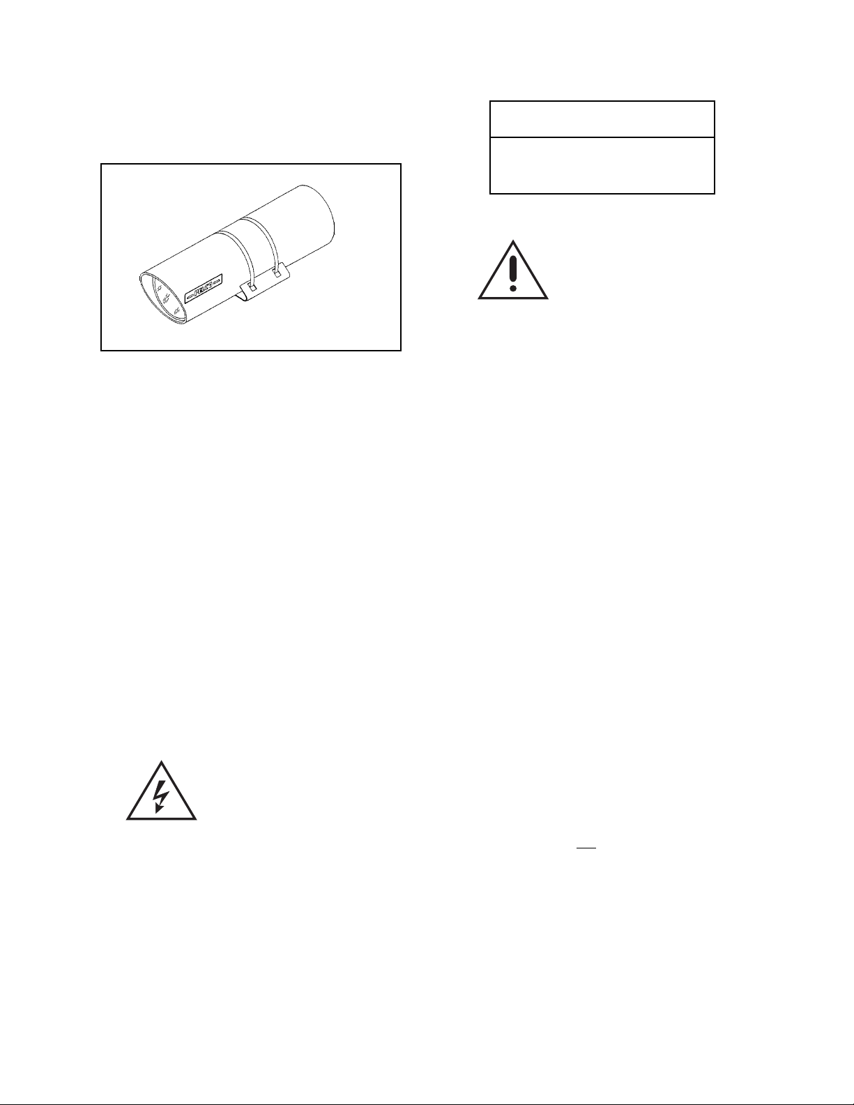
2.0 DESCRIPTION
The EH8000 series enclosures are sealed and
pressurized camera enclosures designed to protect CCTV camera/lens from adverse environmental conditions.
The EH8000 series enclosures are constructed of
aluminum which resists corrosion and may be
used in a wide range of chemical environments
such as acetate solvents, acetone, alcohol, ether,
freon, gasoline, hydrocarbons, hydrogen peroxide, oxygen, sulfur, and turpentine.
The enclosures are not recommended for use in
sodium hydroxide, potassium hydroxide, phosphorous pentoxide, hydroxides, ferric nitrate,
bleaching solutions or acid salts environments.
Pelco Manual C418M (8/97) 1
Page 4

2.1 MODEL NUMBERS
EH8004 4" (10.16 cm) diameter, 17"
(43.18 cm) long pressurized
camera enclosure with lens preset capabilities. Provided with
one (1), 40 watt heater.
EH8006 6" (15.24 cm) diameter, 20"
(50.80 cm) long pressurized
camera enclosure with lens preset capabilities. Provided with
two (2), 80 watt heaters.
EH8006-26 6" (15.24 cm) diameter, 26"
(66.04 cm) long pressurized
camera enclosure with lens preset capabilities. Provided with
two (2), 80 watt heaters.
EH8000RKIT Dry nitrogen recharging kit for
EH8004, EH8006, and EH8008.
Kit includes pressure regulator
and nitrogen.
2.3 RECOMMENDED MOUNTS
AH2000 Manually adjustable head. Use
with PM2000, PM2010 or
WM2000 mounts.
EM22 Medium duty wall mount; sup-
ports up to 40 lbs (18.14 kg).
(Use with EH8004/EH8006 only.)
MM22 Medium duty ceiling/pedestal
mount; supports up to 40 lbs
(18.14 kg). (Use with EH8004/
EH8006 only.)
EH8008 8" (20.32 cm) diameter, 26"
(66.04 cm) long pressurized
camera enclosure with lens preset capabilities. Provided with
two (2), 80 watt heaters.
2.2 OPTIONAL ACCESSORIES
SS8004 Sun shroud for EH8004, designed
to reduce internal enclosure temperature when the enclosure is
subjected to direct sunlight.
SS8006 Same as SS8004 except for
use with EH8006 enclosure.
SS8006-26 Same as SS8004 except for
use with EH8006-26 enclosure.
SS8008 Same as SS8004 except for
use with EH8008 enclosure.
EH8004ORKIT O-ring kit, including desiccant
bags, for EH8004. Required
only if O-rings have been damaged during servicing.
EH8006ORKIT O-ring kit, including desiccant
bags, for EH8006.
EH8008ORKIT O-ring kit, including desiccant
bags, for EH8008.
EH8000LUBE O-ring lubrication kit for EH8000
series enclosures. Recommended for lubing O-rings when
servicing.
PA2000 Adapter plate for medium duty
pan/tilts. Use with WM2000
mount.
PM2000 24" (60.96 cm) high ceiling/
pedestal mount; supports up to
125 lbs (56.70 kg).
PM2010 Same as PM2000 except 10"
(25.4 cm) high.
WM2000 Wall mount; supports up to 75 lbs
(34.02 kg).
2.4 RECOMMENDED CONTROLS
CM7500/CM8500/
CM9500 Series Coaxitron Matrix, System 7500,
8500 or 9500 controls and preset receiver are required for use
with preset lenses. Consult factory for details.
MEHDT Desk top enclosure control de-
signed to provide 120 VAC
power to enclosure for powering heater, cameras, etc.
MEHDT/220 Same as MEHDT except 230
VAC input/230 VAC output.
MEH24DT Desk top enclosure control de-
signed to provide 24 VAC power
to enclosure for powering
heater, cameras, etc.
2 Pelco Manual C418M (8/97)
Page 5

3.0 SPECIFICATIONS
ELECTRICAL
Input Voltage: 120 VAC (230 VAC optional)
for heaters
Power
Requirements:
40 watts (EH8004)
160 watts (all other models)
Connector: Souriau 85107E2016P, 16-pin jam
nut receptacle
Mating
Connector: Souriau 85106EC2016S, MS type
connector (supplied)
Maximum
Camera/Lens
Size:
EH8004 3.75" (9.53 cm) diameter x 14"
(35.56 cm) long or
14"L x 2.8"W x 2.8"H
(35.56 cm x 7.11 cm x 7.11 cm)
EH8006 5.75" (14.61 cm) diameter x 18"
(45.72 cm) long or
18"L x 4.25"W x 4.25"H
(45.72 cm x 10.80 cm x 10.80 cm)
EH8006-26 5.75" (14.61 cm) diameter x 24"
(60.96 cm) long or
24"L x 4.25"W x 4.25"H
(60.96 cm x 10.80 cm x 10.80 cm)
Maximum
Cable Distances:
Wire
Gauge EH8004 All Others
12 10,390 ft (3167 m) 2,640 ft (805 m)
14 6,560 ft (1999 m) 1,660 ft (506 m)
16 4,110 ft (1253 m) 1,040 ft (317 m)
18 2,590 ft (789 m) 650 ft (198 m)
20 1,620 ft (494 m) 410 ft (125 m)
Heater: EH8004, one (1) 40 watt, 120/230
VAC; all others two (2) 80 watt,
120/230 VAC
GENERAL
Construction:Aluminum 6061 T6
Finish:
Outside Gray polyester powder coat
Inside Black anodized
Dimensions: See Figure 1
Front Window:
EH8004 3.75" (9.52 cm) diameter tempered
glass, 0.225" (0.57 cm) thick
EH8006 6" (15.24 cm) diameter tempered
glass, 0.225" (0.57 cm) thick
EH8008 8" (20.32 cm) diameter tempered
glass, 0.225" (0.57 cm) thick
Camera
Mounting: Custom designed depending on
camera/lens
EH8008 7.75" (19.69 cm) diameter x 24"
(60.96 cm) long or
24"L x 5.65"W x 5.65"H
(60.96 cm x 14.35 cm x 14.35 cm)
Enclosure
Mounting: Adjustable cradle secured with
stainless steel bands
Weight:
Model Unit Shipping
EH8004 10 lbs (4.54 kg) 12 lbs (5.44 kg)
EH8006 24 lbs (10.89 kg) 26 lbs (11.79 kg)
EH8006-26 32 lbs (14.51 kg) 34 lbs (15.42 kg)
EH8008 45 lbs (20.41 kg) 47 lbs (21.32 kg)
ENVIRONMENTAL
Ambient
Operating
Temperature: -40° to 122°F (-40° to 50°C)
(with heater)
Vibration: 5 to 60 Hz with 0.082-inch (0.21 cm)
total travel (15 g’s at 60 Hz). From
60 to 1,000 Hz, 5 g’s rms with
random vibration
Altitude: Sea level to equivalent of 10,000
feet (3,048 m)
Acoustic
Noise: Operates in 150 dB acoustic noise
environments
Humidity: MIL-E-540T, para. 3.2.24.7. Up to
100% relative humidity. Equipped
with standard Schraeder and pressure relief valves to provide positive
internal pressure with dry nitrogen.
Pelco Manual C418M (8/97) 3
Page 6

Sand and Dust: MIL-E-5400T, para. 3.2.24.7.
4.1 ENCLOSURE MOUNTING — FIXED
Fungus: MIL-E-5400T, para. 3.2.24.8.
Salt Atmosphere: MIL-E-5400T, para. 3.2.24.9.
Explosion: MIL-E-5400T, para. 3.2.24.10.
(Design and product specifications subject to
change without notice.)
4.0 INSTALLATION
Please check the contents of your package before
proceeding with the installation of the equipment to
ensure that all the mating connectors and associated parts are present. If they are not, contact the
factory to obtain a replacement.
Note: Fasteners to attach the enclosure to the
fixed mount or pan/tilt are not provided in this
package and are not available from Pelco.
The enclosure can be mounted to either a wall
mount or a ceiling/pedestal mount.
For proper mounting, refer to the mounting instructions accompanying the specific mount you are
using.
To insure suitable load bearing, a minimum of 1/4inch (0.63 cm) diameter fasteners should be used
to secure the mount to the mounting surface.
The enclosure should be attached to the mount/
pan/tilt by a minimum of two 1/4-20 fasteners.
Always use a service loop, as shown in Figure 2
and Figure 3, in order to prevent unnecessary
entrance of water.
ENCLOSURE A B C D E F G H I
EH8004 4.0 (10.16) 18.0 (45.72) 4.5 (11.43) 5.5 (13.97) 12.5 (31.75) 17.0 (43.18) 2.0 (5.08) 3.0 (7.62) 6.0 (15.24)
EH8006 6.0 (15.24) 22.0 (55.88) 6.5 (16.51) 7.0(17.78) 13.0 (33.02) 20.0 (50.80) 2.0 (5.08) 7.0(17.78) 6.0 (15.24)
EH8006-26 6.0 (15.24) 28.0 (71.12) 6.5 (16.51) 7.0(17.78) 16.0 (40.64) 26.0 (66.04) 2.0 (5.08) 7.0(17.78) 6.0 (15.24)
EH8008 8.0 (20.32) 28.0 (71.12) 8.5 (21.59) 9.0 (22.86) 16.0 (40.64) 26.0 (66.04) 2.0 (5.08) 7.0(17.78) 6.0 (15.24)
NOTE: VALUES IN PARENTHESES ARE CENTIMETERS; ALL OTHERS ARE INCHES
Figure 1. EH8000 Series Enclosures Dimension Drawing
4 Pelco Manual C418M (8/97)
Page 7

4.2 ENCLOSURE MOUNTING —
PAN/TILT
The enclosure can be mounted to a pan/tilt which
is mounted to a wall or ceiling.
For proper mounting, refer to the mounting instructions accompanying the specific mount and pan/tilt
you are using.
To insure suitable load bearing, a minimum of 1/4-inch
(0.63 cm) diameter fasteners should be used to secure
the mount and/or pan/tilt to the mounting surface.
The enclosure should be attached to the mount/
pan/tilt by a minimum of two 1/4-20 fasteners.
Always use a service loop, as shown in Figure 4
and Figure 5, in order to prevent unnecessary
entrance of water.
Figure 2. Typical Fixed Wall Mounting
Figure 3. Typical Fixed Ceiling Mounting
Figure 4. Typical Pan/Tilt Wall Mounting
Figure 5. Typical Pan/Tilt Ceiling Mounting
Pelco Manual C418M (8/97) 5
Page 8

4.3 CAMERA/LENS INSTALLATION
AND ADJUSTMENTS
To install the camera/lens combination, perform
the following steps:
1. Disassemble the enclosure as specified in the
Maintenance Section, Section 7.0.
CAUTION
Pressure must be released prior
to opening the enclosure or personal injury may result.
2. Install the camera/lens on the camera sled
(Figure 10, item 11) by screwing the camera
to the sled.
3. The enclosure power , lens functions and cam-
era power should be connected as follows
(also see Figures 7 and 8):
Pin # Function
A Video core
B Video shield
E Camera AC (high)
F Camera AC (low)
G Ground
H Enclosure AC (high)
K Iris
L Focus
M Zoom
N Lens Common
P Enclosure AC (low)
The EH8004, EH8006, EH8006-26 and
EH8008 also include lens preset capabilities.
Connections are as follows (refer to Figures 7
and 8):
Pin# Function
C Preset Positioning +5 V
D Preset Positioning Common
R Preset Positioning Focus
S Preset Positioning Zoom
4.4 MATING CONNECTOR ASSEMBLY
To assemble the 16 or 11 pin mating connector for
the EH8000 Series Enclosures, perform the following steps and refer to Figure 6. Note that
enclosures supplied with an 11 pin connector will
be wired according to the diagram in the bottom
half of Figure 7 or 8.
1. Pass the coax and the enclosure control cable
through the cable clamp body (item 5), the cable
grommet (item 4), and the seal ring (item 3), in
that order. Push those components down the
cable approximately 10 inches (25 cm) to allow yourself room to work.
2. Strip the outer jacket from the coax and the
control cable back 2 inches. Strip the individual
conductors of the control cable back 1/4 inch
(0.63 cm).
3. Separate the coax shield from the core insulation and twist into a single strand. Strip the
core insulation back 1 inch (3 cm).
4. Insert the individual conductors into the appropriate holes into the sealing grommet (item 2)
and force them through.
5. Solder the individual conductors to the appropriate pins in the connector body (item 1).
6. Push the sealing grommet ( item 2) into the
back of the connector body (item 1).
7. Slide the seal ring (item 3), the cable grommet
(item 4), and the cable clamp body (item 5) forward to the connector body.
8. Thread the cable clamp body (item 5) onto the
connector body (item 1) and tighten.
9. Position the cable clamp halves (item 6), and attach with the hardware supplied (items 7 and 8).
The cable clamp halves should apply pressure
to the cable grommet (item 4). Tighten all hardware.
Reinstall the camera sled into the body by following the steps shown in the Maintenance, Section
7.3.
6 Pelco Manual C418M (8/97)
Page 9

Figure 6. EH8000 Series Mating Connector Assembly Diagram
Pelco Manual C418M (8/97) 7
Page 10

Figure 7. EH8000 Series Wiring Diagram, 120 VAC (16 or 11 Pin Connector)
8 Pelco Manual C418M (8/97)
Page 11

Figure 8. EH8000 Series Wiring Diagram, 230 VAC (16 or 11 Pin Connector)
Pelco Manual C418M (8/97) 9
Page 12

4.5 SUN SHROUD INSTALLATION
5.1 SYSTEM TEST
The sun shroud provides an air space between
itself and the enclosure to protect the enclosure
from the direct rays of the sun and reduces the
internal temperature of the enclosure approximately 10-15° F (-12.22°-9.44° C).
To install the sun shroud, perform the following
steps (see Figure 9):
1. Insert the mounting straps through the holes
in the standoffs inside the shroud.
2. Align the sun shroud.
3. Fasten the mounting straps securely around
the enclosure.
5.0 OPERATION
To ensure proper operation, the unit should be
installed as previously stated and wired in accordance with Figures 7 and 8.
1. Power up the camera.
2. Check the operation of the lens functions such
as focus, zoom, and iris.
6.0 TROUBLESHOOTING GUIDELINES
1. Once the camera has been powered up and
no picture is present on the monitor, take the
following steps:
a. Verify that the video monitor has been
properly terminated.
b. If the monitor is properly terminated, open
and close the iris to see if a picture appears.
c. If adjusting the iris does not yield a pic-
ture, check the camera for proper voltage.
d. If the above do not restore a picture, con-
tact Pelco’ s T echnical Assistance Program
(TAP) at 1-800-289-9100.
7.0 MAINTENANCE
At a minimum frequency of once each year, the
enclosure should be routinely recharged. Additionally, if the enclosure must be opened for servicing,
the enclosure would also need to be recharged.
The following instructions explain how to disassemble the enclosure, reassemble and charge it.
7.1 ENCLOSURE DISASSEMBLY
1. Disconnect the power from the enclosure.
2. Remove the mating connector from the rear
of the enclosure by turning the outer ring counterclockwise until a click is felt; then pull the
mating portion of the connector off. You may
elect to remove the enclosure from its mount
which will make the disassembly process
much easier.
3. Remove the center cap from the Schraeder
valve. (See Figure 10, item 6).
4. Relieve internal enclosure pressure by de
pressing and holding down the center stem of
the Schraeder valve. (See Figure 10, item 6).
Figure 9. EH8000 Series Sun Shroud
Installation
10 Pelco Manual C418M (8/97)
Page 13

CAUTION: Pressure must be released prior
to opening the enclosure or personal injury
may result.
5. Once the internal pressure has been relieved,
use a screwdriver to pry the end of the spiral
retaining ring (Figure 10, item 5) from the retaining ring groove in the enclosure body.
6. Next, pull on the “T” handle to remove rear
plate from housing. If necessary, use a screwdriver and brace against the hex portion of the
filler valve on the rear plate; grab the “T” handle
and work back and forth to remove rear plate.
7.2 ENCLOSURE SERVICING
Whenever the enclosure is disassembled for servicing, it should be recharged after reassembly
and prior to installation.
Recharging requires the use of a Pelco
EH8000RKIT recharge kit (or equivalent) and applicable O-ring kit, part # EH8004ORKIT,
EH8006ORKIT or EH8008ORKIT.
To prepare the enclosure for recharging, follow the
steps below.
1. Once the enclosure has been disassembled
as mentioned above, remove the O-ring from
the rear plate (Figure 10, item 12) and install
a new O-ring in the O-ring grove in the rear
plate.
2. When the new O-ring has been installed in
the rear plate, smear a liberal amount of the
O-ring lubricant provided with the EH8000 Oring kit on the exterior surface of the O-ring
and rear plate. Replace the desiccant bag in
the enclosure with a new one provided with
the kit.
3. Slide the camera sled (Figure 10, item 11) back
into the body (Figure 10, item 10) making sure
the front lip of the sled is under the retaining
bracket of the enclosure. When fully installed,
the rear plate (Figure 10, item 12) will fit firmly
into the rear opening of the housing and the
retaining grove will be fully visible.
7.3 RECHARGING THE ENCLOSURE
WARNING! Prior to recharging, make sure
the regulator is preset to a pressure not
exceeding 5 lbs.
Exceeding 5 lbs will damage the enclosure.
1. Pressurize the inside of the enclosure using the
EH8000RKIT recharge kit only. Connect the
regulator to the tank by threading the nut into
the socket of the tank valve and tighten with a
wrench. This regulator is factory preset for 5
PSI. Do not attempt to readjust the regulator.
Note: Before turning tank valve on, be sure that
regulator valve is totally open.
2. Once the regulator has been secured to the
tank, open the tank valve.
3. Using the self-holding tire chuck, apply pressure to the enclosure by affixing the tire chuck
to the Schraeder valve on the rear of the enclosure. You must remove the Schraeder valv e
cap first.
4. Remove the plastic cap on the pressure relief valve on the rear of the enclosure. Using
a small screwdriver to hold it open. At this
point, allow the nitrogen to flow through the
enclosure until the humidity indicator registers the lowest humidity level (changing color
from green/blue to pink). The humidity indicator can be viewed through the front window of the enclosure looking at the inside top
of the enclosure. Once the humidity indicator registers the lowest level, remove the
screwdriver and allow nitrogen to continue to
flow into the enclosure until you no longer
hear the flow of nitrogen from the tank to the
enclosure.
Hint: Having the window of the enclosure point
up toward the sky will greatly reduce the
purge time necessary to remove oxygen
from the enclosure.
5. Remove the tire chuck from the Schraeder
valve and apply the Schraeder v alve cap . Also ,
replace the plastic cap on the pressure relief
valve. The enclosure is ready for service.
4. Reinstall the spiral retaining ring (Figure 10,
item 5) in the retaining grove in the rear of the
enclosure.
5. Proceed to Section 7.3 for recharging instructions.
Pelco Manual C418M (8/97) 11
Page 14

8.0 EXPLODED ASSEMBLY DIAGRAM
Figure 10. EH8000 Series Enclosures Exploded Assembly Diagram
9.0 EH8000 SERIES ENCLOSURES MECHANICAL PARTS LIST
The following parts lists correspond to Figure 10.
EH8004 MECHANICAL PARTS LIST
Item No. Qty Description Part Number
1 1 Connector, solder receptacle jam nut CON85107E2016P
2 2 Strap, cradle E7064004COMP
3 1 Cradle enclosure E7084003COMP
4 1 Glass, 4.105" diameter x .225" EH800410000
5 2 Ring, retaining, spiral SS EH800410001
6 1 Valve, tank, Schraeder 9166-L8 EH800610004
7 1 Bag, desiccant EH800610005
8 3 “O” RING EH800410006
9 1 Valve, pressure relief EH800610007
10 1 Body assembly EH8001000WA
11 1 Camera sled EH80044001COMP
12 1 Rear plate EH80044002COMP
13 1 Sealing ring, window EH80044003COMP
14 1 Not used —
15 1 Not used —
16 1 Terminal block jumper TRB140-J-1
17 2 Terminal block, 4-position TRB4-140
18 1 Screw, 1/4-20 x .375 flat, Phillips Hd, SS ZH1/4-20X.375SP
19 1 Screw, 1/4-20 x .125 flat, Phillips Hd, SS ZH1/4-20X1.25SP
20 2 Screw, 6-32 x 1/4" pan, Phillips Hd, SS ZH6-32X.250SPP
21 4 Screw, 6-32 x 1/2" pan, Phillips Hd, SS ZH6-32X.500SPP
22 6 Washer, internal star #6, SS ZH6LWSIS
12 Pelco Manual C418M (8/97)
Page 15

EH8006, EH8006-26 MECHANICAL PARTS LIST
Item No. Qty. Description Part Number
1 1 Connector, solder receptacle jam nut CON85107E2016P
2 2 Strap, cradle E7064004COMP
3 1 Cradle enclosure E7084003COMP
4 1 Glass, 6.100" diameter x .225" EH800610000
5 2 Ring, retaining, spiral SS EH800610001
6 1 Valve, tank, Schraeder 9466-L8 EH800610004
7 1 Bag, Desiccant EH800610005
8 3 “O” RING EH800610006
9 1 Valve, pressure relief EH8000610007
10 1 Body assembly EH80064000COMP
11 1 Camera sled EH80064001COMP
12 1 Rear plate EH80064002COMP
13 1 Sealing ring, window EH80064003COMP
14 1 Elevation block EH80064004COMP
15 1 Camera sled spacer EH80064006COMP
16 1 Terminal block jumper TRB140-J-1
17 3 Terminal block, 4-position TRB4-140
18 1 Screw, 1/4-20 x .375 flat, Phillips Hd, SS ZH1/4-20X.375SP
19 1 Screw, 1/4-20 x .125 flat, Phillips Hd, SS ZH1/4-20X1.25SP
20 2 Screw, 6-32 x 1/4" pan, Phillips Hd, SS ZH6-32X.250SPP
21 4 Screw, 6-32 x 1/2" pan, Phillips Hd, SS ZH6-32X.500SPP
22 6 Washer, internal star #6, SS ZH6LWSIS
23 1 Handle (not shown) EHP10000
24 1 Screw, 10.24 x .750, self sealing (not shown) EHP10001
25 1 Screw, 10-32 x .375, self sealing (not shown) EHP10011
EH8008 MECHANICAL PARTS LIST
1 1 Connector, solder receptacle jam nut CON85107E2016P
2 2 Strap, cradle EHX8244166COMP
3 1 Cradle enclosure EHD94270COMP
4 1 Glass, 8.100" diameter x .355" EH800810000
5 2 Ring, retaining, spiral SS EH800810001
6 1 Valve, tank, Schraeder 9466-L8 EH800610004
7 1 Bag, Dessiccant EH800610005
8 3 “O” RING EH800810006
9 1 Valve, pressure relief EH800610007
10 1 Body assembly EH80081000WA
11 1 Camera sled EH80084001COMP
12 1 Rear plate EH80084002COMP
13 1 Sealing ring, window EH80084003COMP
14 1 Not used —
15 1 Not used —
16 1 Terminal block jumper TRB140-J-1
17 3 Terminal block, 4-position TRB4-140
18 1 Screw, 1/4-20 x .375 flat, Phillips Hd, SS ZH1/4-20X.375SP
19 1 Screw, 1/4-20 x .125 flat, Phillips Hd, SS ZH1/4-20X1.25SP
20 2 Screw, 6-32 x 1/4" pan, Phillips Hd, SS ZH6-32X.250SPP
21 4 Screw, 6-32 x 1/2" pan, Phillips Hd, SS ZH6-32X.500SPP
22 6 Washer, internal star #6, SS ZH6LWSIS
Note: The mating connector for item #1 in all parts lists is part # CON85106EC2016S, which is not shown.
10.0 EH8000 SERIES ENCLOSURES ELECTRICAL PARTS LIST
Item No. Qty. Description Part Number
1 1 Thermostat (not shown) EH5510049A
2 1 Heater blanket (not shown), EH8004 only EHWD10087
2 Heater blanket (not shown), All other models ED210048
Pelco Manual C418M (8/97) 13
Page 16

11.0 WARRANTY AND RETURN
INFORMATION
WARRANTY
If a warranty repair is required, the Dealer must
contact Pelco at (800) 289-9100 or (559) 292-1981
to obtain a Repair Authorization number (RA), and
provide the following information:
Pelco will repair or replace, without charge, any
merchandise proved defective in material or workmanship for a period of one (1) year after the date
of shipment. Exceptions to this warranty are as
noted below:
• Two (2) years on all standard motorized and
fixed focal length lenses.
• T wo (2) years on Legacy®, Intercept®, CM8500/
CM9500/CM9750/CM9760 Matrix, Spectra™,
DF5 Series and DF8 Fixed Dome products.
• Two (2) years on WW5700 series window
wiper (excluding wiper blades).
• Two (2) years on cameras.
• Six (6) months on all pan and tilts, scanners
or preset lenses used in continuous motion
applications (e.g., preset scan, tour and auto
scan modes).
Pelco will warranty all replacement parts and repairs for 90 days from the date of Pelco shipment.
All goods requiring warranty repair shall be sent
freight prepaid to Pelco, Clovis, California. Repairs
made necessary by reason of misuse, alteration,
normal wear, or accident are not covered under
this warranty.
Pelco assumes no risk and shall be subject to no
liability for damages or loss resulting from the specific use or application made of the Products. Pelco’ s
liability for any claim, whether based on breach of
contract, negligence, infringement of any rights of
any party or product liability, relating to the Products shall not exceed the price paid by the Dealer
to Pelco for such Products. In no event will Pelco
be liable for any special, incidental or consequential damages (including loss of use, loss of profit
and claims of third parties) however caused,
whether by the negligence of Pelco or otherwise.
1. Model and serial number
2. Date of shipment, P.O. number, Sales Order
number, or Pelco invoice number
3. Details of the defect or problem
If there is a dispute regarding the warranty of a
product which does not fall under the warranty conditions stated above, please include a written explanation with the product when returned.
Ship freight prepaid to: Pelco
300 West Pontiac Way
Clovis, CA 93612-5699
Method of return shipment shall be the same or
equal to the method by which the item was received by Pelco.
RETURNS
In order to expedite parts returned to the factory
for repair or credit, please call the factory at (800)
289-9100 or (559) 292-1981 to obtain an authorization number (CA number if returned for credit,
and RA number if returned for repair). Goods returned for repair or credit should be clearly identified with the assigned CA/RA number and freight
should be prepaid. All merchandise returned for
credit may be subject to a 20% restocking and refurbishing charge.
Ship freight prepaid to: Pelco
300 West Pontiac Wa y
Clovis, CA 93612-5699
The above warranty provides the Dealer with specific legal rights. The Dealer may also have additional rights, which are subject to variation from
state to state.
14 Pelco Manual C418M (8/97)
 Loading...