

Page 1
®
EH66/EH66X
Environmental Enclosures
Installation/Operation Manual
C411M-D (1/96)
Pelco • 3500 Pelco Way, Clovis, CA 93612-5699 • USA • www.pelco.com
(559) 292-1981 or (800) 289-9100 • FAX (559) 292-3827 or (800) 289-9150
Pelco Manual C411M-D (1/96) 17
Page 2

TABLE OF CONTENTS
Section Page
1.0 WARNINGS ........................................................................................................................................1
2.0 SCOPE ............................................................................................................................................... 2
3.0 DESCRIPTION ................................................................................................................................... 2
3.1 CERTIFICATIONS ....................................................................................................................2
4.0 INSTALLATION ..................................................................................................................................3
4.1 ELECTRICAL CONNECTIONS/BLOWER AND HEATER ........................................................ 3
4.2 INSTALLATION OF CAMERA/LENS ........................................................................................3
4.3 FIXED ENCLOSURE MOUNTING ...........................................................................................5
4.4 PAN/TILT ENCLOSURE MOUNTING ....................................................................................... 6
4.5 WINDOW WIPER INSTALLATION ............................................................................................8
4.6 B66KIT/E624HB/H66KIT INSTALLATION ................................................................................ 9
5.0 CARE AND MAINTENANCE ..............................................................................................................9
6.0 EXPLODED ASSEMBLY DIAGRAMS .............................................................................................. 10
7.0 MECHANICAL PARTS LISTS .......................................................................................................... 12
7.1 MECHANICAL PARTS LIST WW66 AND WW66-5/220 ASSEMBLY .....................................13
8.0 OPTIONAL ACCESSORIES ............................................................................................................ 14
9.0 SPECIFICATIONS ............................................................................................................................14
9.1 RECOMMENDED CABLE SIZE .............................................................................................15
9.2 POWER REQUIREMENTS FOR BLOWER, HEATER, ACCESSORIES ............................... 15
10.0 WARRANTY AND RETURN INFORMATION ...................................................................................16
ii PELCO Manual C411M-C (1/96)
Page 3

LIST OF ILLUSTRATIONS
Figure Page
1 EH66/EH66X Dimension Drawing ................................................................................................. 2
2 Wiring Diagram for Window Defroster, Wiper/Washer and Blower/Heater Assemblies................. 4
3 EH66 Enclosure with Wall Mount .................................................................................................. 5
4 EH66 Enclosure with Pedestal/Ceiling Mount ............................................................................... 5
5 EH66 Enclosure with Pan/Tilt and Wall Mount .............................................................................. 6
6 EH66 Enclosure with Pan/Tilt and Pedestal/Ceiling Mount ........................................................... 6
7 Window Wiper Motor Installation ................................................................................................... 7
8 Mounting Hole Dimensions ........................................................................................................... 7
9 EH66 Enclosure Exploded Assembly Diagram ............................................................................. 9
10 WW66, WW66-5/220 Wiper Exploded Assembly Diagram ......................................................... 10
REVISION HISTORY
Manual # Date Comments
C411M 8/88 Original Manual
C411M 5/91 Revision A. Revised to include new series models; cable distance
information, and the addition of the WW66 installation information as well
as new manual format
C411M 11/92 Revision B. Revised to include new wiring diagram information for
accessory kits as well as WW66 motor installation/mounting information.
C411M-C 2/95 Revision C. Manual revised to include new dimension drawing; the addition
of rubber grommet to WW66 BOM as per ECO #94-091; changes to the
WW66 exploded view diagram as per ECO #94-233; installation instructions
incorporated as per ECO #92-129; completely new EH66 exploded assembly
drawing with new materials list; new mounting hole dimension drawing and
window wiper assembly drawing as per ECO # 93-200; and minor corrections
to wiring diagram.
C411M-D 1/96 Revision D. Manual revised to include new wiper/washer pump as per ECO
95-431.
Pelco, the Pelco logo, Camclosure, Esprit, Genex, Legacy, and Spectra are registered trademarks ofPelco. ©Copyright 1998, Pelco. All rights reserved.
Endura and ExSite are trademarks of Pelco.
Pelco Manual C411M-D (1/96) iii
Page 4

This page intentionally left blank.
iv Pelco Manual C411M-D (1/96)
Page 5
INSTALLATION/OPERATION MANUAL
MODEL EH66/EH66X SERIES
ENVIRONMENTAL ENCLOSURES
1.0 WARNINGS
Prior to installation and use of this product, the following
WARNINGS should be observed.
1. Installation and servicing should only be done by
Qualified Service Personnel and conform to all
local codes.
2. Unless the unit is specifically marked as a NEMA
Type 3, 3R, 3S, 4, 4X, 6, or 6P enclosure, it is
designed for indoor use only and it must not be
installed where exposed to rain and moisture.
3. Only use replacement parts recommended by Pelco.
The product and/or manual may bear the
following marks:
This symbol indicates that dangerous voltage
constituting a risk of electric shock is present
within this unit.
4. After replacement/repair of this unit’s electrical
components, conduct a resistance measurement
between line and exposed parts to verify the exposed
parts have not been connected to line circuitry.
5. The installation method and materials should be
capable of supporting four times the weight of the
enclosure, pan/tilt, camera and lens combination.
This symbol indicates that there are important
operating and maintenance instructions in the
literature accompanying this unit.
CAUTION:
TO REDUCE THE RISK OF ELECTRICAL
SHOCK, DO NOT REMOVE COVER. NO
USER-SERVICEABLE PARTS INSIDE.
REFER SERVICING TO QUALIFIED
SERVICE PERSONNEL.
RISK OF ELECTRIC SHOCK.
CAUTION:
DO NOT OPEN.
Please thoroughly familiarize yourself with the information in this manual
prior to installation and operation.
Pelco Manual C411M-D (1/96) 1
Page 6
2.0 SCOPE
The information contained within this manual covers
the EH66/EH66X Series environmental enclosure.
3.0 DESCRIPTION
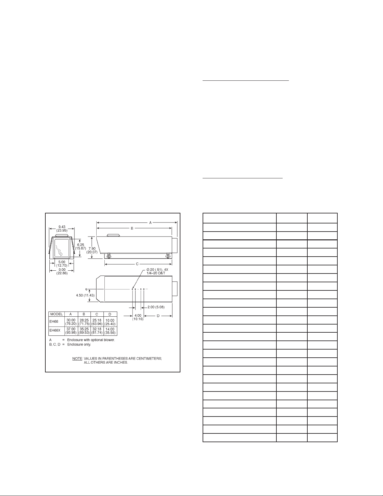
The EH66 Series is an all-weather environmental enclosure for 2/3" and 1" cameras with a maximum camera/
lens size of 7" W x 7" H x 22" L (17.7 cm x 17.7 cm x
55.8 cm). Rugged all aluminum construction protects
the camera from adverse weather conditions. Built-in
sun visor shields the lens from direct sunlight, and a vent
cap allows heated air to escape from the interior. Removable lid with four secure latches provides convenient access. Camera is mounted on an adjustable rail/
sled. Two adjustable glands in the bottom of the enclosure permit easy cable entry.
The EH66X Series is the same as the EH66 Series
except the enclosures have extra length to accommo-
Figure 1. EH66/EH66X Dimension Drawing
date intensified cameras. The EH66X Series will accept
a maximum camera/lens size of 7" W x 7" H x 30" L
(17.7 cm x 17.7 cm x 76.2 cm).
Models With The Letters “HB” in the suffix come
equipped with a factory installed filtered blower and
wired blanket heater with thermostat controls. The
heater activates when the internal temperature falls
below 40° F (4.44° C). It is electrically insulated from
the enclosure and provides 160 watts of heat. The
blower provides 105 CFM and activates when the
internal temperature reaches approximately 100° F
(37.78° C). Internal temperature is reduced when the
blower draws ambient air from a filtered intake port,
circulates it through the enclosure, and exhausts it out
the vent cap.
Models With The Letter “L” in the suffix include
tamper resistant locks which are keyed alike.
3.1 CERTIFICATIONS
Model Number UL CE
EH66 X X
EH66/WW X
EH66B X
EH66B/WW X
EH66BL X
EH66H X
EH66HB X
EH66HB/WW X
EH66HB-3 X
EH66HBL X
EH66HBL/WW X
EH66HL X
EH66L X X
EH66L/WW X
EH66X X X
EH66X/WW X
EH66XB X
EH66XBL X
EH66XH X
EH66XHB X
EH66XHB/WW X
EH66XHBL X
EH66XHBL/WW X
EH66XHL X
EH66XL X X
EH66XL/WW X
2 Pelco Manual C411M-D (1/96)
Page 7

4.0 INSTALLATION
Please check the contents of your package(s) for the
following items before proceeding with the installation
of the equipment.
Quantity Item
2 1/4-20 x .500 hex head screws to mount
camera
1 5/32-inch Allen wrench for adjusting sled
1 Blower assembly (installed on models
with “HB” in suffix only)
1 Heater assembly (installed on models with
“HB” in suffix only)
NOTE: Cameras with a low optical centerline
or using a large diameter lens require an elevation block (1 inch or 2 inch) for proper positioning. See Section 8.0, Optional Accessories,
for the correct model number.
3. Replace the camera/sled assembly onto the rail and
slide along the rail to adjust the camera to maximum forward camera position; lock into place by
tightening the Allen head screws.
IMPORTANT: Set the focus for the shortest
distance to extend the lens to the maximum
length before positioning the camera/lens combinations. This will ensure that the lens has
enough clearance and will not hit the window
during focusing.
2 Keys (for models with “L” in suffix only)
4.1 ELECTRICAL CONNECTIONS –
ENCLOSURES WITH BLOWER AND
HEATER
Factory installed heater and blower assemblies are
factory pre-wired and only require connection of power
to the terminal block (see Figure 2). Refer to Section 4.6
for field installed heater/blower kits.
NOTE: In dusty locations, double filters can
be installed. Loosen the two Allen head screws
at the rear of the enclosure and pull the drawer
open. Remove the acorn nuts at the rear of the
housing and pull the end plate off for access to
the filters.
4.2 INSTALLATION OF CAMERA/LENS
To install the camera/lens, perform the following:
1. Remove the lid by unlatching the two latches on
each side.
4. Loosen the cable gland nuts on the back of the
enclosure (1/2-inch gland for video cable, 3/8-inch
gland for power cable). Route the camera cables
through the appropriate glands and connect to the
camera. Wire the enclosure per wiring diagram
provided (see Figure 2). Tighten the gland nuts for
a snug fit around the cables.
NOTE: The plate holding the two cable glands
on the bottom of the enclosure is removable,
which allows enough clearance for the connector assemblies to be inserted in or removed from
the enclosure. This permits the connectors (i.e.,
lens connector, video connector, etc.) to be assembled somewhere other than the field and
also allows the enclosure to be moved in the
field without disassembling all the connectors.
5. Replace the lid and secure the latches.
6. Attach the enclosure to the appropriate mount or
pan and tilt using the instructions provided with the
mounting equipment.
2. Remove the camera sled from the rail by loosening
the two Allen head screws and attach the camera/
lens with the 1/4-20 hex head screws provided.
Pelco Manual C411M-D (1/96) 3
Page 8

to control
Figure 2. Wiring Diagram for Window Defroster, Wiper/Washer and Blower/Heater Assemblies
4 Pelco Manual C411M-D (1/96)
Page 9

4.3 FIXED ENCLOSURE MOUNTING
3. Attach the adjustable head to the mount.
The are two types of mounts that can be used with the
EH66 enclosure: wall, or pedestal/ceiling (see Figures
3 and 4).
Instructions for mounting the enclosure are as follows:
1. Select the appropriate mount (WM2000 for wall
mounting or PM2000/PM2010 for pedestal mounting) for the application.
The mount must be equipped with the AH2000
adjustable head for precise positioning of the enclosure.
2. Secure the mount to a suitable load bearing
surface. Use fasteners with a minimum 1/4-inch
diameter.
4. Align the 1/4-20 threaded holes in the bottom of the
EH66 enclosure with the holes in the tilt table of the
adjustable head. Fasten the enclosure to the table
using 1/4-20 fasteners (not to exceed 5/8" in length,
minimum two (2).
5. If you have not already done so, install the camera/
lens according to the instructions in Section 4.2 of
this manual.
6. Make all necessary electrical connections.
7. Position the enclosure to the desired viewing angle
and tighten all fasteners.
Figure 3. EH66 Enclosure with Wall Mount
Pelco Manual C411M-D (1/96) 5
Figure 4. EH66 Enclosure with
Pedestal/Ceiling Mount
Page 10

4.4 PAN/TILT ENCLOSURE MOUNTING
The EH66 enclosure can also be mounted to a pan/tilt
assembly in addition to the wall or pedestal/ceiling
mount.
To include the pan/tilt assembly in your configuration,
perform the following steps:
4. Attach the pan/tilt to the mount. The pan/tilt control
connect should be positioned towards the building/
mounting location. Note the “front” label on the
pan/tilt.
5. If you have not already done so, install the
camera/lens according to the instructions in
Section 4.2 of this manual.
1. Select the appropriate mount (WM2000 for wall
mounting, PM2000/PM2010 for pedestal mount)
for the application.
2. Select the appropriate pan/tilt for the application.
Considerations must be made as to enclosure options, camera and lens selection, and environmental conditions. All of these will affect the pan/tilt
selection.
3. Secure the mount to a suitable load bearing surface.
Use fasteners with a minimum 1/4-inch diameter.
6. Balance the enclosure/camera/lens load on the tilt
table. Adjust the positioning as needed to align the
mounting holes. A minimum of two 1/4-20 x 5/8"
fasteners must be used. Secure the enclosure to the
tilt table.
7. Make all necessary electrical connections. Be sure
to leave an adequate loop of cables between the
enclosure and the pan/tilt, and the enclosure and the
rigid mount to prevent binding and/or strain on the
cables (see Figures 5 and 6).
Figure 5. EH66 Enclosure with Pan/Tilt and
Wall Mount
6 Pelco Manual C411M-D (1/96)
Figure 6. EH66 Enclosure with Pan/Tilt and
Pedestal/Ceiling Mount
Page 11

4.5 WINDOW WIPER INSTALLATION
To install the window wiper kit, perform the following
steps and refer to Figures 7 and 8:
1. Turn the EH66 enclosure over so the bottom is
facing up.
2. If necessary, lay out the locations of the four (4)
.171-inch diameter mounting holes using the dimensions given in Figure 8.
4. Attach the wiper box using the four (4) mounting
holes, inserting the wire leads through one of the
rubber grommets.
5. Adjust the force of the wiper blade against the
glass by applying force to the arms toward the
glass or away from glass.
6. Attach wiper wire leads inside the enclosure as
shown in Figure 2.
7. Connect cable to wiper box.
8. Attach the water reservoir bottle to the rear of the
EH66 enclosure by removing the two (2) top acorn
nuts.
9. Place the bottle mount on the protruding studs and
replace the acorn nuts.
10. Attach the water hose to the bottle from the wiper.
Figure 7. Window Wiper Motor Installation
Figure 8. Mounting Hole Dimensions
Pelco Manual C411M-D (1/96) 7
Page 12

4.6 B66KIT/E624HB/H66KIT
INSTALLATION
All heater and blower kits are supplied partially assembled. Install in the enclosure according to the following instructions:
1. Remove the round cap on the rear of the enclosure
and the two (2) 8-32 screws and nuts located on
each side of the opening above the horizontal line.
5.0 CARE AND MAINTENANCE
Maintenance performed at regularly scheduled intervals will help prolong the operational life and appearance of the equipment.
1. Clean the plexi-glass window with a mild nonabrasive detergent in water and a soft cloth regularly to
help maintain picture clarity. For a heavily soiled
window, use vinyl cleaner.
2. Remove the two (2) acorn nuts holding the air box
to the heater/blower assembly; remove the air box.
3. Install the assembly in the enclosure utilizing the
two (2) open holes for mounting; reinstall the air
box on the outside of the enclosure and secure the
assembly with the two (2) acorn nuts.
4. Mount the two (2) heater strips onto the sides of the
enclosure with the four (4) sheet metal screws
provided.
5. Wire input power to the terminal block on the top of
the heater/blower assembly as shown in Figure 2.
2. Clean or replace the fiberglass filter pad in the
blower assembly periodically. To replace or clean
the filter pad, perform the following steps:
a. Remove the two acorn nuts at the rear of the
housing and pull the end plate off for access to
the filter.
b. Remove the wire screen and filter pad. Clean
the pad with water and mild detergent, dry
thoroughly, and reinsert or replace with a new
pad. (Replacement pads, part number
EH14050COMP, are available from Pelco.)
NOTE: Pelco offers a 24-hour, seven-day-a
week Technical Assistance Program (TAP) designed to assist any customer with a technical
problem involving Pelco equipment whether it’s
the weekend or late at night. For technical assistance dial (800) 289-9100 and you will be
connected to a Pelco TAP member who is
trained to answer your questions.
Pelco also guarantees one-day turnaround on any Pelco
equipment sent in for repair. This includes warranty and
non-warranty items. Refer to the section on “Warranty
and Return Information” in this manual for the proper
procedure.
8 Pelco Manual C411M-D (1/96)
Page 13

6.0 EXPLODED ASSEMBLY DIAGRAMS
See Figures 9 and 10 for exploded assembly diagrams of the EH66 enclosure and WW66, WW66-5/220 wiper assembly.
Figure 9. EH66 Enclosure Exploded Assembly Diagram
Pelco Manual C411M-D (1/96) 9
Page 14

NOTE: FIGURE DOES NOT REPRESENT
CURRENT PUMP IN USE.
Figure 10. WW66, WW66-5/220 Wiper Exploded Assembly Diagram
10 Pelco Manual C411M-D (1/96)
Page 15

7.0 MECHANICAL PARTS LISTS
7.1 MECHANICAL AND ELECTRICAL PARTS LIST FOR EH66 ENCLOSURE
Item No. Qty Description Part Number
1 4 Gasket, Window Frame EH110042
2 1 Gasket, Cable Entry EH110072
3 1 Plate, Cable Entry EH14231COMP
4 2 Gasket, Rim EH450010000
5 2 Gland, UL, PG-13.5 black EH470010007B
6 2 Nut, UL Gland, 13.5 EH470010008B
7 4 Fastener, Lid Link Lock EH550010010B
8 8 Gasket, Poron EH550010030
9 1 Camera Sled EH55004100COMP
10 1 Body Weld Assy EH661000WA
1 Body Weld Assy (EH66X) EH66X1000WA
11 1 Glass 1/4 X 5-9/16 X 6-11/16 EH6610051
12 1 Screen Vent Cap EH664000COMP
13 1 Bar Vent Cap EH664001COMP
14 1 Lid EH664228COMP
1 Lid (EH66X) EH66X4228COMP
15 2*, 1** Vent Cap *, ** EH664229COMP
16 1 Frame, Window EH664230COMP
17 4 Lug, Spade 16-20AWG CON52929-1**
18 2 Heater Blanket, 1" X 17", 120VAC, 80W ED210048 **
19 1 Filter, Fiberglass Cut EH14050COMP **
20 1 Filter Screen EH14051COMP **
21 1 Air Box EH14242COMP **
22 1 Fan, Tube 120VAC EH18013 **
23 1 Gasket, Closed Cell EH5510042 **
24 1 Thermostat, SC-100-A EH5510045A **
25 1 Thermostat, OA-60 EH5510049A **
26 1 Bracket, Terminal Block EH664002COMP **
27 2 Bracket, Heater Strip EH664003COMP **
28 1 Terminal Block, 6-pos TRB6-141 **
29 2 Plate Block EH664104COMP **
A 2*, 1** Screw, 10-32 X 1.25 Pan Phil SS ZH10-32X1.25SPS
B 2 Screw, 10-32 X 2.00 Pan Phil SS ZH10-32X2.00SPP
C 10 Screw, 10-32 X 3/8 Pan Phil SS ZH10-32X.375SPP
D 2 Nut, Acorn, 10-32 SS ZH10-32NUTCA
E 6*, 8** Nut, Hex, 10-32 SS ZH10-32NUTSH
F 2 Washer, Split Lock Washer ZH10LWSSL
G 6 Washer, Nylon ZH200X.437X62N
H 2*, 3** Washer, Flat #10 ZH204X436X60C
I 6 Internal Tooth Lock Washer #10 ZH10LWSIS
J 4** Screw, 6-32 X 1/4 Pan Phil ZH6-32X.250SPP
K 4 Screw, 6-32 X 3/8 Truss SS ZH6-32X.375STS
L 8** Screw, 6-32 X 1/2 Pan Phil ZH6-32X.500SPP
M 8 Screw, 6-32 X 5/8 Pan Phil ZH6-32X.625SPP
N 4** Screw, 6-32 X 3/8 Type F, Pan Phil` ZH6-SFX/375SPP
O 4** Nut, Hex, 6-32 ZH6-32X.32NUTSH
P 12, 16** Internal Tooth Lock Washer, #6 ZH6LWSIS
Q 8 Screw, 4-40 X 3/8 Pan Phil ZH4-40X.375SPP
R 8 Nut, Hex, 4-40 ZH4-40NUTSH
S 8 Internal Tooth Lock Washer ZH4LWSIS
*EH66, EH66X
**EH66HB
***EH66L
Pelco Manual C411M-D (1/96) 11
Page 16

7.2 MECHANICAL PARTS LIST FOR WW66 AND WW66-5/220
WINDOW WIPER ASSEMBLY
Item No. Qty Description Part Number
1 3 Bearing 776003
2 1 Diode DIOPT40F
3 — Not used —
4 1 Switch SWIV3L
5 1 Spacer, 1/4" Hex x .6254-40 tap SPA8404
6 1 Transformer TRF21162.01.0CM
7 1 Pump WW6610031
8 12 Tubing, Vinyl, 1/8 ID x 1/4 OD x in. WW6610007
9 42 Tubing, Vinyl, 1/4 ID x 3/8 OD x in. WW6610005
10 1 Solenoid valve WW650010010
11 3 Spacer Shaft, #84-9 WW6610010
12 1 Roller Plate WW661006COMP
13 1 Follower Arm WW661011COMP
14 1 Wiper Washer Enclosure WW664000COMP
15 1 Bracket, Wiper Motor WW664001COMP
16 1 Motor, 120 VAC (model WW66) WW664017COMP
Motor, 230 VAC (model WW66-5/220) WW664020COMP
17 1 Wiper Arm WW664003COMP
18 1 Wiper Blade Clevis WW664204COMP
19 1 Wiper Idler Arm WW664005COMP
20 1 Bearing Block WW664010COMP
21 1 Wiper Blade WW664214COMP
22 1 Tube, Spray WW66 WW664015COMP
23 2 Fitting, BARBXMNPT WW650010020
24 1 Lid, Enclosure WW664016COMP
25 2 Fitting, BARB, 1/4 tube x 1/8 NPT WW6610008
26 1 4-position CPC pin receptacle CON206061-1
27 1 Cable, 4-position female WIRA220036
1 Bottle, cap, hanger WW6610004
1 Bottle cover WW664900COMP
12 Pelco Manual C411M-D (1/96)
Page 17

8.0 OPTIONAL ACCESSORIES
FACTORY INSTALLED
EHRC Relay module for low voltage control
of wiper/washer and camera on/off.
Requires MEH24DT control module.
TI66 Thermal insulation provides increased
thermal protection for enclosure and
contents at extreme temperatures (for
model EH66 series only).
T166X Thermal insulation for model EH66X
series.
H66KIT Heater kit, 120 VAC, for EH66/EH66X
enclosures. (For 230 VAC option, wire
heaters in series.)
L66KIT Tamper proof lock kit.
S66 Sun shroud, provides an air space be-
tween the sun shroud and the enclosure
to protect the enclosure from the direct
rays of the sun. Reduces internal temperature approximately 10-15° (for
model EH66 only).
S66X Sun shroud for model EH66X.
WD66 Window defroster and defogger, 120
VAC, 80 watt operation, prevents ice
buildup or condensation of moisture
on the window caused by temperature
and humidity. Must be used with heater/
blower assembly.
WD66/220 Same as WD66 except 230 VAC, 80
watt operation.
WW66 Window wiper and washer assembly,
120 VAC operation, designed to remove moisture and dirt from the window by remote control. The washer
enhances cleaning ability of wiper and
has a one quart reservoir for water or
antifreeze solution, which is recommended for low temperature applications.
WW66-5/220 Same as WW66 except 230 VAC, 50 Hz.
FIELD INSTALLED
B66KIT Blower kit, 105 CFM, 13.4 watts at 60
Hz, 120 VAC, for EH66/EH66X enclosures.
BK66KIT/220 Blower kit, 90 CFM, 15 watts at 50
Hz, 230 VAC, for EH66/EH66X enclosures.
E624HB Heater/blower kit, 24 VAC, for Mod-
els EH66/EH66X.
MISCELLANEOUS
EB1 Elevation block 1", required for cam-
eras having a low optical centerline or
using a large diameter lens.
EB2 Elevation block 2", same as EB1, ex-
cept 2" high.
NOTE: Fasteners to secure mounts are not supplied. (Minimum 1/4" diameter recommended.)
9.0 SPECIFICATIONS
ELECTRICAL
Input Voltage: 120 VAC, 60 Hz (230 VAC
optional)
Electrical
Connection: 6-pin terminal strip
GENERAL
Construction: 5052H32 aluminum
Finish: Polyester powder coat
Weight: EH66 — 11 lbs (4.98 kg)
EH66X — 14 lbs (6.34 kg)
Dimensions: See Figure 1
Cable Entry: Two adjustable 1/2" sealable
glands, mounted on removable
plate for ease of assembly.
EHCM Cradle mount for inverted mounting of
enclosure when used with PM2000/
AH2000 ceiling mount or pan and tilts.
Pelco Manual C411M-D (1/96) 13
Latches: Link lock fasteners
Window: 1/4" thick plate glass
Camera Mounting: Adjustable rail/sled
Page 18

9.1 RECOMMENDED CABLE SIZE
9.2 POWER REQUIREMENTS FOR
BLOWER, HEATER, ACCESSORIES
CAUTION: When a single power source is
used for both the camera and accessories, the
camera power consumption must be taken into
consideration when determining the wire gauge.
The following cable sizes are the minimum recommended for use with the combination of defroster/
blower/heater/camera. Cable distances specified assume a 10% line voltage loss:
Input
Voltage 22 Awg 20 Awg 18 Awg 16 Awg
The blower, heater and electrically powered accessories
use the following wattage when in operation:
Blower:
24 VAC: 7.2 watts (AC rectified)
120 VAC: 13.5 watts at 60 Hz
230 VAC: 15 watts at 50 Hz
Heater:
120 VAC or
230 VAC: 160 watts
24 VAC: 75 watts
Defroster
Assembly: 80 watts
Wiper/Washer
Assembly: 95 watts
Camera: Assuming 7 watts
Camera (7 w) 115 5,852' 9,306' 14,806' 23,498'
220 6,526 m 10,377 m 16,510 m 26,203 m
Cam/Wiper (102 w) 115 401' 638' 1,016' 1,612'
220 447 m 712 m 1,133 m 1,798 m
Cam/Wiper/Def (182 w) 115 225' 357' 569' 903'
220 251 m 399 m 635 m 1,007 m
Cam/Heater/Blower (177.5 w) 115 231' 368' 585' 929'
220 258 m 410 m 652 m 1,036 m
Cam/Heater/Blower/Def (257.5 w) 115 165' 263' 419' 665'
220 184 m 294 m 467 m 742 m
Cam/Heater/Blower/Wiper (272.5 w) 115 160' 255' 406' 645'
220 179 m 284 m 453 m 719 m
Cam/Heater/Blow/Def/Wiper (352.5 w) 115 119' 190' 303' 480'
220 133 m 212 m 337 m 536 m
14 Pelco Manual C411M-D (1/96)
Page 19

10.0 WARRANTY AND RETURN
INFORMATION
PRODUCT WARRANTY AND RETURN INFORMATION
WARRANTY
Pelco will repair or replace, without charge, any merchandise proved defective in material or
workmanship for a period of one year after the date of shipment.
Exceptions to this warranty are as noted below:
• Five years on FT/FR8000 Series fiber optic products.
®
• Three years on Genex
• Three years on Camclosure® and fixed camera models, except the CC3701H-2,
CC3701H-2X, CC3751H-2, CC3651H-2X, MC3651H-2, and MC3651H-2X camera models,
which have a five-year warranty.
• Two years on standard motorized or fixed focal length lenses.
• Two years on Legacy
fixed dome products.
• Two years on Spectra
continuous motion applications.
• Two years on Esprit
• Eighteen months on DX Series digital video recorders, NVR300 Series network video
recorders, and Endura
• One year (except video heads) on video cassette recorders (VCRs). Video heads will be
covered for a period of six months.
• Six months on all pan and tilts, scanners or preset lenses used in continuous motion
applications (that is, preset scan, tour and auto scan modes).
Pelco will warrant all replacement parts and repairs for 90 days from the date of Pelco
shipment. All goods requiring warranty repair shall be sent freight prepaid to Pelco, Clovis,
California. Repairs made necessary by reason of misuse, alteration, normal wear, or accident
are not covered under this warranty.
Pelco assumes no risk and shall be subject to no liability for damages or loss resulting from
the specific use or application made of the Products. Pelco’s liability for any claim, whether
based on breach of contract, negligence, infringement of any rights of any party or product
liability, relating to the Products shall not exceed the price paid by the Dealer to Pelco for
such Products. In no event will Pelco be liable for any special, incidental or consequential
damages (including loss of use, loss of profit and claims of third parties) however caused,
whether by the negligence of Pelco or otherwise.
The above warranty provides the Dealer with specific legal rights. The Dealer may also have
additional rights, which are subject to variation from state to state.
Series products (multiplexers, server, and keyboard).
®
, CM6700/CM6800/CM9700 Series matrix, and DF5/DF8 Series
®
, Esprit®, ExSite™, and PS20 scanners, including when used in
®
and WW5700 Series window wiper (excluding wiper blades).
™
Series distributed network-based video products.
If a warranty repair is required, the Dealer must contact Pelco at (800) 289-9100 or
(559) 292-1981 to obtain a Repair Authorization number (RA), and provide the following
information:
1. Model and serial number
2. Date of shipment, P.O. number, Sales Order number, or Pelco invoice number
3. Details of the defect or problem
If there is a dispute regarding the warranty of a product which does not fall under the
warranty conditions stated above, please include a written explanation with the product
when returned.
Method of return shipment shall be the same or equal to the method by which the item was
received by Pelco.
RETURNS
In order to expedite parts returned to the factory for repair or credit, please call the factory at
(800) 289-9100 or (559) 292-1981 to obtain an authorization number (CA number if returned
for credit, and RA number if returned for repair).
All merchandise returned for credit may be subject to a 20% restocking and refurbishing
charge.
Goods returned for repair or credit should be clearly identified with the assigned CA or RA
number and freight should be prepaid. Ship to the appropriate address below.
If you are located within the continental U.S., Alaska, Hawaii or Puerto Rico, send goods to:
Service Department
Pelco
3500 Pelco Way
Clovis, CA 93612-5699
If you are located outside the continental U.S., Alaska, Hawaii or Puerto Rico and are
instructed to return goods to the USA, you may do one of the following:
If the goods are to be sent by a COURIER SERVICE, send the goods to:
Pelco
3500 Pelco Way
Clovis, CA 93612-5699 USA
If the goods are to be sent by a FREIGHT FORWARDER, send the goods to:
Pelco c/o Expeditors
473 Eccles Avenue
South San Francisco, CA 94080 USA
Phone: 650-737-1700
Fax: 650-737-0933
This equipment contains electrical or electronic components that must be recycled properly to comply with Directive 2002/96/EC of the European Union
regarding the disposal of waste electrical and electronic equipment (WEEE). Contact your local dealer for procedures for recycling this equipment.
Pelco Manual C411M-D (1/96) 15
Page 20

®
Pelco
3500 Pelco Way, Clovis, CA 93612-5699 • (559) 292-1981 • (800) 289-9100
FAX (559) 292-3827 • (800) 289-9150 • www.pelco.com
International customers call 1-559-292-1981 or FAX 1-559-348-1120
(Product specifications subject to change without notice.)
C411M-D
16 Pelco Manual C411M-D (1/96)
 Loading...