

Page 1
®
WW57 Series
Window Wiper Kit
for EH5700 Series
and EH5700L Legacy
®
Series Enclosures
Installation/
Operation Manual
C1432M-C (11/99)
Pelco • 3500 Pelco Way, Clovis • CA 93612-5699 USA • www.pelco.com
In North America and Canada: Tel (800) 289-9100 or FAX (800) 289-9150
International Customers: Tel +1 (559) 292-1981 or FAX +1 (559) 348-1120
Page 2

CONTENTS
LIST OF ILLUSTRATIONS
Section Page
IMPORTANT SAFEGUARDS AND WARNINGS ................................................................3
DESCRIPTION ...................................................................................................................4
MODELS ....................................................................................................................4
INSTALLATION................................................................................................................... 4
WINDOW WIPER KIT MODIFICATION ..................................................................... 4
WINDOW WIPER KIT INSTALLATION ......................................................................7
MAINTENANCE ................................................................................................................ 15
SERVICE MANUAL ...................................................................................................15
WARRANTY AND RETURN INFORMATION ................................................................... 16
Figure Page
1 Wiper Modification ............................................................................................. 4
2 Wiper Circuit Board Component Locations ........................................................5
3 Circuit Side of Wiper Board ................................................................................5
4Wiper Driver Schematic ..................................................................................... 6
5Wiper Drive Shaft Installation ............................................................................. 8
6Wiper Shaft/Wiper Assembly Connector ............................................................ 8
7 Wiper Circuit Board Component Locations ........................................................8
8 Component Locations for Optional Circuit Board (O/I-PCB) ............................. 11
9 Wiper On/Off Connection ..................................................................................11
10 Exploded Assembly Diagram for Window Wiper ...............................................13
LIST OF TABLES
Table Page
A 24 VAC Wiring Distances .................................................................................. 12
B Exploded Assembly Parts List for Window Wiper .............................................. 14
2 Pelco Manual C1432M-C (11/99)
Page 3
IMPORTANT SAFEGUARDS AND WARNINGS
Prior to installation and use of this product, the following WARNINGS should be observed.
1. Installation and servicing should only be done by qualified service personnel and conform to all local codes.
2. Unless the unit is specifically marked as a NEMA Type 3, 3R, 3S, 4, 4X ,6 or 6P enclosure, it is designed for indoor use only and it must not be installed where exposed to
rain and moisture.
3. Only use replacement parts recommended by Pelco.
The product and/or manual may bear the following marks:
This symbol indicates that dangerous voltage constituting a risk of electric shock is
present within this unit.
This symbol indicates that there are important operating and maintenance instructions
in the literature accompanying this unit.
Please thoroughly familiarize yourself with the information in this manual prior to installation
and operation.
CAUTION:
RISK OF ELECTRIC SHOCK.
DO NOT OPEN.
Pelco Manual C1432M-C (11/99) 3
Page 4
DESCRIPTION
Window wiper kits in the WW57 Series are for installation in the EH5700 Series and
EH5700L Legacy® Series environmental enclosures.
MODELS
WW5723-1 Window wiper kit for EH5723/EH5723L, 120 VAC, 15 watts
WW5723-2 Window wiper kit for EH5723/EH5723L, 24 VAC, 15 watts (CE)
WW5723-3 Window wiper kit for EH5723/EH5723L, 230 VAC, 15 watts (CE)
WW5729-1 Window wiper kit for EH5729/EH5729L, 120 VAC, 15 watts
WW5729-2 Window wiper kit for EH5729/EH5729L, 24 VAC, 15 watts (CE)
WW5729-3 Window wiper kit for EH5729/EH5729L, 230 VAC, 15 watts (CE)
INSTALLATION
Window wiper kits in the WW57 Series are designed to operate with an AC voltage to turn
on the wiper. However, the kits must be modified to use +5 to +10 VDC to turn on the wiper
when the kits are used with Pelco’s receivers.
If you are going to use a Pelco receiver, proceed to the
tion.
If you are going to use equipment that provides AC power to control the wiper, proceed to
the
Window Wiper Kit Installation
section.
WINDOW WIPER KIT MODIFICATION
Modify your wiper kit if it is to be operated from any of the following Pelco receivers:
CX9000 Series
WX8000 Series
LRD41 Series
ERD97P21-U with the ERD97P-AUX option board
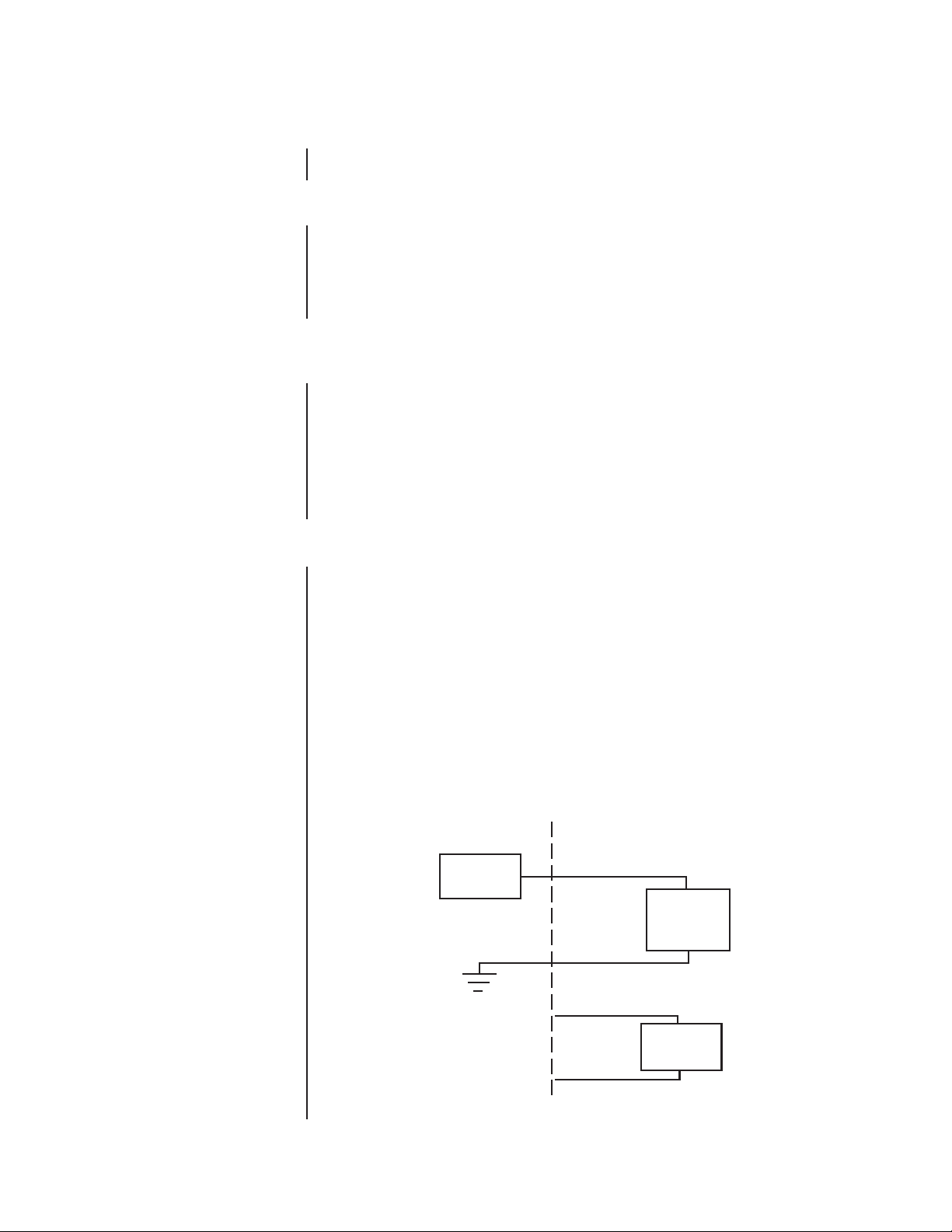
This modification only changes the voltage that is required to turn on the wiper. The wiper
motor still requires AC voltage (refer to Figure 1).
To modify a kit:
1. Remove the circuit board cover from the wiper motor/control assembly and remove the
circuit board (PCB9000275 Rev. E). Refer to Figure 10 for parts locations.
Refer to Figure 2 for steps 2-5.
RECEIVER ENCLOSURE
AUX
OUTPUT
Window Wiper Kit Modification
+5 TO +10 VDC
sec-
WIPER
ON/OFF
CIRCUIT
LENS COMMON
AC HI
AC NT
WIPER
MOTOR
Figure 1. Wiper Modification
4 Pelco Manual C1432M-C (11/99)
Page 5
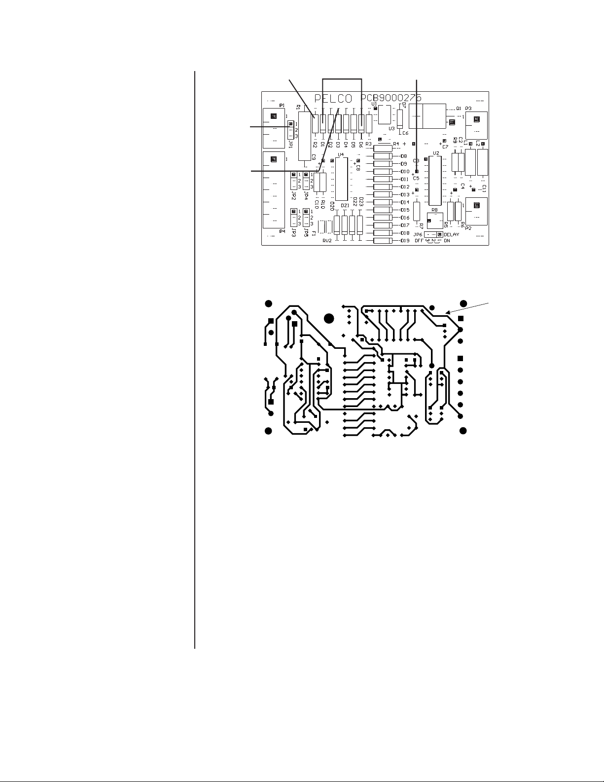
JP1
ADD
GREEN
WIRE
HERE
R2
D1-D6
C3
Figure 2. Wiper Circuit Board Component Locations
PCB9000275 REV. E
X
P14719
CUT
TRACE
HERE
Figure 3. Circuit Side of Wiper Board
2. Remove diodes D1 through D6.
3. Replace resistor R2 with a 1/4-watt 470-ohm resistor.
4. Remove capacitor C3.
5. Connect an 18-inch (45.72 cm) length of 22-gauge green wire to the hole in the circuit
board for the anode of D3.
6. Turn the circuit board over and cut the trace as shown in Figure 3.
Figure 4 shows schematically the changes that were made in steps 2-7.
7. Reinstall the circuit board in the wiper motor/control assembly and reconnect the wiring. Refer to Figure 7.
Proceed to the
Window Wiper Kit Installation
section.
Pelco Manual C1432M-C (11/99) 5
Page 6

JP1
P1
1
2
3
1
2
3
R1 15K 5W
CHANGE TO 470
Ω
YEL
VIO
BR
R3
22
U1
4N26
12
P4
1
2
3
4
5
6
JP2
110–220
110–220
JP3 JP4 JP5
3
2
1
3
2
1
3
2
1
3
2
1
F1
1.0A TRIP
RV2
D20
D22
D21
D23
D19
D18
D17
D16
D15 D14
D13 D12 D11 D10 D9 D8 R4 1K
3
U3 LM78L05
GND
Vin
Vo
2
1
+5
+ C7
3.3uF
35V
+ C8
+ C6
470uF
35V
3.3uF
35V
R5
10K
+ C3
6.8uF
35V
4
5
+5
+5
1
2
A
B
74HC221A
3
R/C
Ce
Q
Q
C4
4.7uF
35V
+
+5
R8
220K
4 1
5 1
U2A
13
4
0
10
C5
22uF
15V
+
6
7
U2B
R7
220K
R8 200K
5
12
A
B
Q
Q
R/C
Ce
74HC221A
+5
1
2
U4A
74HC132
3
R10
4.7K
C10
0.1uF
C2
0.1uF
L1 4.7uH
L2 4.7uH
+
C11
1uF
35V
1
2
P2
P3
1
2TIP29
Q1
D7
R9
1K
C9
22uF
15V
+
JUMPERS
INPUT
24 VAC
INPUT
100 VAC
INPUT
115 VAC
INPUT
230 VAC
JP2
1–2 2–3 2–3 1–2
JP3
1–2 2–3 2–3 1–2
JP4 1–2 2–3
2–3
2–3
JP5
1–2 2–3 2–3
2–3
JP6
DELAY ON DELAY OFF
1–2
2–3
CUT TRACE
GRN WIRE
TO LENS
COMMON
CONFIGURE JUMPER
JP6
DELAY ON
DELAY OFF
1
2
3
CLR
CLR
D1
D2
D3
D4
D5
D6
R2 4.7K
REMOVE D1–D6
REMOVE C3
11
Figure 4. Wiper Driver Schematic
6 Pelco Manual C1432M-C (11/99)
Page 7

WINDOW WIPER KIT INSTALLATION
For the following instructions, refer to Figure 10, if necessary. Table B lists the parts shown
in Figure 10.
1. Turn off power to the enclosure.
2. Unlatch and raise the enclosure lid. The gas spring will hold the lid in place when it is
fully opened.
3. Remove the camera and sled.
4. EH5723/EH5723L and EH5729/EH5729L Models Only - Remove the vent
grill inside the enclosure at the rear of the unit.
5. EH5723-1, -2, -3/EH5723L-1, -2, -3 Models, and EH5729-1, -2, -3/
EH5729L-1, -2, -3 Models Only
a. Unplug the electrical connector on the fan.
b. Remove the three screws that secure the fan plate and fan to the enclosure.
c. Remove the fan plate and fan.
d. Remove the fan from the fan plate.
e. Attach the fan to the fan plate of the window wiper assembly in the same orienta-
tion that it was attached to the original fan plate.
6. Refer to Figure 5 and insert the wiper shaft into the green bushing on the fan plate of
the wiper motor/control assembly.
7. Insert the motor/control assembly into the enclosure and attach the assembly to the
enclosure with the hardware that is supplied:
a. Slip the blue, white, and black wiper wires into the slot at the bottom of the fan
plate so that the white plug is on the opposite side of the fan plate from the wiper
circuit board housing.
b. On all models except the EH5723 and EH5729, remove the screws on the sides
of the circuit board in the enclosure so that the circuit board can be moved out of
the way to install the wiper motor/control assembly.
c. Place the assembly into the enclosure with the wiper circuit board housing facing
toward the rear of the enclosure and the fan plate against the camera sled track.
d. Hook the rear of the circuit board mounting over the screw installed at the top of
the enclosure’s rear panel. Secure the circuit board mounting to the enclosure
with the acorn nut.
e. Attach the bottom right and bottom left sides of the fan plate to the camera sled
track with screws and lock washers.
f. On all models except the EH5723 and EH5729, reinstall the circuit board.
8. Reconnect the electrical connector to the fan.
9. Remove the latch on the side of the enclosure where the wiper shaft is located.
10. Slide the support bracket onto the wiper shaft. Using the longer screws supplied in the
wiper kit, attach the latch and support bracket to the enclosure.
11. Slide the flange bearing over the bearing pin as shown in Figure 5, and slide the cam
track over the flange bearing. Only the tautness of the drive shaft holds the flange
bearing in place.
12. Refer to Figure 6 and slip the flex coupler over the drive shaft.
13. Remove the hole plug from the wiper shaft hole in the front of the enclosure.
14. From the outside of the enclosure, install the green bushing into the wiper shaft hole.
Pelco Manual C1432M-C (11/99) 7
Page 8

Slide the flange bearing over the bearing pin.
Switch Pin
Bearing Pin
Flange Bearing
Drive shaft.
Cam
Cam Track
Drive Shaft
Slide the drive arm forward until the bearing pin sets inside the
cam track of the drive shaft. Only the tautness of the drive shaft
assembly holds the flange bearing in place.
Figure 5. Wiper Drive Shaft Installation
BLU
WHT
PCB9000276
BLK
Power input to
BLK
BLK/WHT
BLU
BLU/WHT
Transformer
BRN
BRN/WHT
Flex coupler.
Allen cap screws
After joining the drive shaft and the drive arm on the wiper
assembly with the use of the flex coupler, secure the drive assembly by tightening the Allen cap screws in the coupler.
Figure 6. Wiper Shaft/Wiper Assembly Connector
GRN
YEL
RED
BLK
C
NO
NC
+
M
_
Input Input Input
24 VAC 120 VAC 230 VAC
JP1 1 - 2 2 - 3 2 - 3
JP2 1 - 2 2 - 3 1 - 2
JP3 1 - 2 2 - 3 1 - 2
JP4 1 - 2 2 - 3 2 - 3
JP5 1 - 2 2 - 3 2 - 3
Figure 7. Wiper Circuit Board Component Locations
8 Pelco Manual C1432M-C (11/99)
Page 9

15. Remove the two screws on the bottom of the enclosure under the window and install
the wiper assembly with two Allen cap screws that are supplied in the parts bag. Make
sure the shaft of the wiper arm goes through the green bushing on the front of the enclosure.
16. Looking at the front of the enclosure from the outside, position the wiper blade so that
it is on the left side of the window as you look at it.
17. Slide the flex coupler over the wiper arm shaft and tighten the two screws in the coupler to secure it to the drive shaft and the wiper arm shaft.
18. Remove the cover over the circuit board on the wiper motor/control assembly.
19. Refer to Figure 7 and set either of the following two options:
a. The time between wiper strokes can be adjusted between 3 and 10 seconds by
rotating the potentiometer R8. Turn the adjustment clockwise to increase the time.
The potentiometer only makes one revolution.
or
b. The wiper can be set to operate continuously by placing the delay jumper at JP6
in the OFF position.
20. Verify that jumpers JP1 through JP5 are set for the correct input voltage.
If you modified the circuit board, place JPI in the 1–2 position. This will route the DC
voltage from the receiver to the on/off circuit of the wiper. Never place the jumper in
the 2–3 position or the wiper will not work.
21. Replace the cover over the circuit board on the wiper motor/control assembly.
WARNING:
If you
use an AC control,
AC high to turn on
the wiper must come from
the same circuit that provides
power to the wiper. This is
because the wiper and the
on/off control share the
same AC neutral. Refer to
Figure 9. This will prevent
damage to the wiper.
22. If you modified the circuit board, connect the green wire from the anode of D3 to either
of the following:
• If your enclosure has the O/I-PCB circuit board (PCB9000276), connect the wire
to the LENS COM connector (refer to Figure 8).
• If your enclosure does not have the circuit board, connect the wire to the LENS
COM connector on your pan/tilt unit or receiver.
23. EH5723 and EH5729 Models Only – Wire the wiper assembly to power as fol-
lows:
Black wire AC HI
White wire AC NT
Blue wire Wiper on/off control
If you modified the circuit board, wire the wiper on/off control to an auxiliary output on
the receiver.
All window wiper assemblies use 15 watts of power. If you are using 24 VAC, refer to
Table A to determine the size of wire to use.
24. All Models Except the EH5723 and EH5729 – Wire the wiper assembly to
power as follows:
a. Remove the plastic cover from the power supply section of the circuit board in
front of the fan plate.
b. Connect the plug from the wiper assembly into the W/W socket on the circuit
board.
c. Wire the wiper on/off control.
If you modified the circuit board, wire the wiper on/off control to an auxiliary output on the receiver.
Pelco Manual C1432M-C (11/99) 9
Page 10

If you are installing the wiper kit in a Legacy enclosure, power for the wiper is
supplied through the 37-pin connector on the pan/tilt unit as follows:
AC High Pin 15
AC Neutral Pin 16
Wiper On/Off Control Pin 25
If you are installing the wiper kit in a non-Legacy unit, power for the wiper is supplied as follows:
AC High Pin 1 of TB2 on the O/I-PCB circuit board (refer to Figure 8)
AC Neutral Pin 2 of TB2 on the O/I-PCB circuit board
Wiper On/Off Control Pin 1 of TB3 on the O/I-PCB circuit board
Pins 15 and 16 on Legacy enclosures and pins 1 and 2 of TB2 on non-Legacy
enclosures also provide power for other enclosure accessories, such as the fan
and heaters. Make sure that this wiring can handle the additional power for the
wiper. All window wiper assemblies use 15 watts of power.
d. Replace the plastic cover over the power supply on the circuit board.
25. Reinstall the camera and sled.
26. Close the enclosure lid.
27. Turn on power to the enclosure.
10 Pelco Manual C1432M-C (11/99)
Page 11

Figure 8. Component Locations for Optional Circuit Board (O/I-PCB)
Figure 9. Wiper On/Off Connection
Pelco Manual C1432M-C (11/99) 11
Page 12

Table A. 24 VAC Wiring Distances
The following are the recommended maximum distances for 24 VAC applications and are
calculated with a 10-percent voltage drop. (Ten percent is generally the maximum allowable
voltage drop for AC-powered devices.)
Wire Gauge
EXAMPLE:
An enclosure
that requires 80 vA and is
installed 35 feet (10 m) from
the transformer would
require a minimum wire
gauge of 20 AWG.
NOTE:
Distances are
calculated in feet; values in
parentheses are meters.
20 18 16 14 12 10
10 283 451 716 1142 1811 2880
(86) (137) (218) (348) (551) (877)
20 141 225 358 571 905 1440
(42) (68) (109) (174) (275) (438)
30 94 150 238 380 603 960
(28) (45) (72) (115) (183) (292)
40 70 112 179 285 452 720
(21) (34) (54) (86) (137) (219)
50 56 90 143 228 362 576
(17) (27) (43) (69) (110) (175)
60 47 75 119 190 301 480
(14) (22) (36) (57) (91) (146)
70 40 64 102 163 258 411
(12) (19) (31) (49) (78) (125)
80 35 56 89 142 226 360
(10) (17) (27) (43) (68) (109)
90 31 50 79 126 201 320
(9) (15) (24) (38) (61) (97)
100 28 45 71 114 181 288
(8) (13) (21) (34) (55) (87)
110 25 41 65 103 164 261
(7) (12) (19) (31) (49) (79)
120 23 37 59 95 150 240
Total vA consumed
(7) (11) (17) (28) (45) (73)
130 21 34 55 87 139 221
(6) (10) (16) (26) (42) (67)
140 20 32 51 81 129 205
(6) (9) (15) (24) (39) (62)
150 18 30 47 76 120 192
(5) (9) (14) (23) (36) (58)
160 17 28 44 71 113 180
(5) (8) (13) (21) (34) (54)
170 16 26 42 67 106 169
(4) (7) (12) (20) (32) (51)
180 15 25 39 63 100 160
(4) (7) (11) (19) (30) (48)
190 14 23 37 60 95 151
(4) (7) (11) (18) (28) (46)
200 14 22 35 57 90 144
(4) (6) (10) (17) (27) (43)
Maximum distance from transformer to load
12 Pelco Manual C1432M-C (11/99)
Page 13

SUPPLIED WITH
BLOWER KIT
6
4
A
16
Figure 10. Exploded Assembly Diagram for Window Wiper
Pelco Manual C1432M-C (11/99) 13
Page 14

Table B. Exploded Assembly Parts List for Window Wiper
Item Qty Description Part Number
11Cam Assembly WW57001000ASSY
21Wiper Arm Assembly MF00-5701-016
31Wiper Shaft (EH5729 Series) MF00-5701-015
1 Wiper Shaft (EH5723 Series) MF00-5701-029
41Wiper Driver Circuit Board Mount WW57004013COMP
51Wiper Motor 570010012
61Wiper Driver Circuit Board Cover WW57004014COMP
71Flex Coupling 570010014
81Fan Plate MF00-5701-010
91Bronze Bearing Flange 776003
10 1 Wiper Driver Circuit Board PCB9000275ASSY
11 2 5/32 Hex 3/16 x 2-56 Standoff SPA8300
12 1 Switch Actuator SWlJS221
1 Switch SWl1SM1
13 1 Transformer (-1, -3 models) TRF21240.70.7CM
14 2 Teflon Bearing Flange WW550010001
15 3 Wiper Blade (by the inch) WW570010050
16 1 Support Bracket MF01-5700-028
17 1 Switch Shield (not shown) MF01-5700-033
A1Grommet GRO2170
B8Nylon Washer #6 ZH131X361X62N
D2Hex Nut, 2-56 ZH2-56NUTSH
E2Screw, 2-56 x 3/4-inch, Pan Head, Phillips ZH2-56X.750SPS
F4Internal Tooth Lock Washer, #2 ZH2LWSIS
H3Screw, 4-40 x 1/4-inch, Pan Head, Phillips ZH4-40X.250SPP
I5Internal Tooth Lock Washer, #4 ZH4LWSIS
J11Cap Screw, 6-32 x 3/8-inch, Allen Socket Head ZH6-32X.375CS
K2Cap Screw, 4-40 x 3/8-inch, Allen Socket Head ZH4-40X.375CS
L1Nut, 6-32, Acorn ZH6-32NUTCA
M2Hex Nut, 6-32 (-1, -3 models) ZH6-32NUTSH
N12Internal Tooth Lock Washer, #6 ZH6LWSIS
14 Pelco Manual C1432M-C (11/99)
Page 15

MAINTENANCE
As necessary, clean the window with a mild non-abrasive detergent in water and a soft cloth
to maintain picture clarity.
To order replacement wiper blades, use the part number WW570010050 (3 inches).
SERVICE MANUAL
If you need to service the wiper assembly, obtain a service manual in one of the following
ways:
• Go to Pelco’s web site at ftp://www.pelco.com and find service manual C1431SM.PDF.
• Contact Pelco’s Literature Department and request service manual C1431SM.
Pelco Manual C1432M-C (11/99) 15
Page 16

PRODUCT WARRANTY AND RETURN INFORMATION
WARRANTY
Pelco will repair or replace, without charge, any merchandise proved defective in material or
workmanship for a period of one year after the date of shipment.
Exceptions to this warranty are as noted below:
• Five years on FT/FR8000 Series fiber optic products.
®
• Three years on Genex
• Three years on Camclosure® and fixed camera models, except the CC3701H-2,
CC3701H-2X, CC3751H-2, CC3651H-2X, MC3651H-2, and MC3651H-2X camera models,
which have a five-year warranty.
•Two years on standard motorized or fixed focal length lenses.
•Two years on Legacy
fixed dome products.
•Two years on Spectra
continuous motion applications.
•Two years on Esprit
• Eighteen months on DX Series digital video recorders, NVR300 Series network video
recorders, and Endura
• One year (except video heads) on video cassette recorders (VCRs). Video heads will be
covered for a period of six months.
• Six months on all pan and tilts, scanners or preset lenses used in continuous motion
applications (that is, preset scan, tour and auto scan modes).
Pelco will warrant all replacement parts and repairs for 90 days from the date of Pelco
shipment. All goods requiring warranty repair shall be sent freight prepaid to Pelco, Clovis,
California. Repairs made necessary by reason of misuse, alteration, normal wear, or accident
are not covered under this warranty.
Pelco assumes no risk and shall be subject to no liability for damages or loss resulting from
the specific use or application made of the Products. Pelco’s liability for any claim, whether
based on breach of contract, negligence, infringement of any rights of any party or product
liability, relating to the Products shall not exceed the price paid by the Dealer to Pelco for
such Products. In no event will Pelco be liable for any special, incidental or consequential
damages (including loss of use, loss of profit and claims of third parties) however caused,
whether by the negligence of Pelco or otherwise.
The above warranty provides the Dealer with specific legal rights. The Dealer may also have
additional rights, which are subject to variation from state to state.
Series products (multiplexers, server, and keyboard).
®
, CM6700/CM6800/CM9700 Series matrix, and DF5/DF8 Series
®
, Esprit®, ExSite™, and PS20 scanners, including when used in
®
and WW5700 Series window wiper (excluding wiper blades).
™
Series distributed network-based video products.
If a warranty repair is required, the Dealer must contact Pelco at (800) 289-9100 or
(559) 292-1981 to obtain a Repair Authorization number (RA), and provide the following
information:
1. Model and serial number
2. Date of shipment, P.O. number, Sales Order number, or Pelco invoice number
3. Details of the defect or problem
If there is a dispute regarding the warranty of a product which does not fall under the
warranty conditions stated above, please include a written explanation with the product
when returned.
Method of return shipment shall be the same or equal to the method by which the item was
received by Pelco.
RETURNS
In order to expedite parts returned to the factory for repair or credit, please call the factory at
(800) 289-9100 or (559) 292-1981 to obtain an authorization number (CA number if returned
for credit, and RA number if returned for repair).
All merchandise returned for credit may be subject to a 20% restocking and refurbishing
charge.
Goods returned for repair or credit should be clearly identified with the assigned CA or RA
number and freight should be prepaid. Ship to the appropriate address below.
If you are located within the continental U.S., Alaska, Hawaii or Puerto Rico, send goods to:
Service Department
Pelco
3500 Pelco Way
Clovis, CA 93612-5699
If you are located outside the continental U.S., Alaska, Hawaii or Puerto Rico and are
instructed to return goods to the USA, you may do one of the following:
If the goods are to be sent by a COURIER SERVICE, send the goods to:
Pelco
3500 Pelco Way
Clovis, CA 93612-5699 USA
If the goods are to be sent by a FREIGHT FORWARDER, send the goods to:
Pelco c/o Expeditors
473 Eccles Avenue
South San Francisco, CA 94080 USA
Phone: 650-737-1700
Fax: 650-737-0933
REVISION HISTORY
Manual # Date Comments
C1432M 10/95 Original manual.
C1432M-A 4/96 Revision A. Revised installation instructions.
C1432M-B 3/98 Added Section 3.1. Moved service information to manual C1431SM.
C1432M-C 11/99 Revised Figure 10 to show new support bracket and modified wiper shafts. Revised installation instructions to add support
bracket.
®Pelco and the Pelco logo are registered trademarks of Pelco. © Copyright 1999, Pelco. All rights reserved.
16 Pelco Manual C1432M-C (11/99)
 Loading...