

Page 1
®
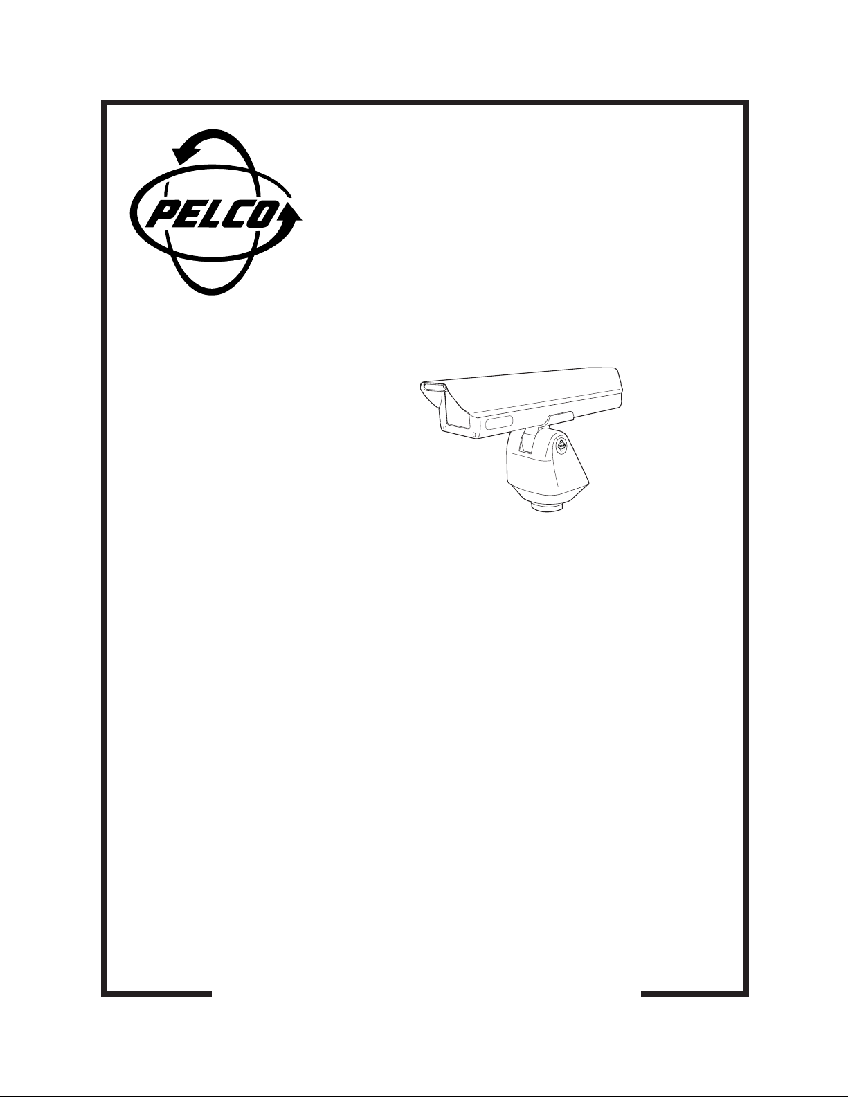
EH4718L/WPSA and
EH4718L/PSA
Environmental
Enclosures
Installation/
Operation Manual
C1415M-PSA (12/97)
Pelco • 3500 W. Pelco Way, Clovis • CA 93612-5699 USA • www.pelco.com
In North America and Canada: Tel (800) 289-9100 or FAX (800) 289-9150
International Customers: Tel (1-559) 292-1981 or FAX (1-559) 348-1120
Page 2

CONTENTS
Section Page
1.0 GENERAL .................................................................................................. 1
1.1 IMPORTANT SAFEGUARDS AND WARNINGS ............................... 1
2.0 DESCRIPTION ..........................................................................................2
2.1 MODELS ............................................................................................2
3.0 INSTALLATION .......................................................................................... 3
4.0 WINDOW WIPER ADJUSTMENTS ...........................................................5
5.0 OPERATION ..............................................................................................6
6.0 MAINTENANCE .........................................................................................7
7.0 WIRING DIAGRAM ....................................................................................8
8.0 SPECIFICATIONS ..................................................................................... 9
9.0 WARRANTY AND RETURN INFORMATION ...........................................10
LIST OF ILLUSTRATIONS
Figure Page
1 Support Bracket Installation ...............................................................4
2 Wiper Circuit Board Component Locations ........................................ 5
3 EH4718L/WPSA and EH4718L/PSA Wiring Diagram ....................... 8
4 EH4718L/WPSA and EH4718L/PSA Dimension Drawing .................9
REVISION HISTORY
Manual # Date Comments
C1415M-PSA 1/97 Original version.
12/97 Changed ENGEH4718L/WPSA to EH4718L/WPSA,
changed ENGEH4718L/PSA to EH4718L/PSA, and
changed manual to new format.
ii
12 Pelco Manual C1415M-PSA (12/97)
Page 3
1.0 GENERAL
1.1 IMPORTANT SAFEGUARDS AND WARNINGS
Prior to installation and use of this product, the following WARNINGS should be
observed.
1. Installation and servicing should only be done by Qualified Service Personnel
and conform to all Local codes.
2. Unless the unit is specifically marked as a NEMA Type 3, 3R, 3S, 4, 4X, 6, or
6P enclosure, it is designed for indoor use only and it must not be installed
where exposed to rain and moisture.
3. Only use replacement parts recommended by Pelco.
4. After replacement/repair of this unit’s electrical components, conduct a resistance measurement between line and exposed parts to verify the exposed
parts have not been connected to line circuitry.
5. The installation method and materials should be capable of supporting four
(4) times the weight of the enclosure, pan/tilt, camera and lens combination.
The product and/or manual may bear the following marks:
This symbol indicates that dangerous voltage constituting a
risk of electric shock is present within this unit.
This symbol indicates that there are important operating and
maintenance instructions in the literature accompanying this
unit.
CAUTION:
RISK OF
ELECTRIC SHOCK.
DO NOT OPEN.
TO REDUCE THE RISK OF ELECTRICAL SHOCK,
DO NOT REMOVE COVER. NO USER-
SERVICEABLE PARTS INSIDE. REFER SERVICING
TO QUALIFIED SERVICE PERSONNEL.
CAUTION:
Please thoroughly familiarize yourself with the information
in this manual prior to installation and operation.
Pelco Manual C1415M-PSA (12/97) 1
Page 4

2.0 DESCRIPTION
The EH4718L/WPSA and EH4718L/PSA environmental enclosures are constructed
of aluminum. They are installed by attaching the bottom of the enclosure to the tilt
shaft of an PT780-24P/PPPSA pan/tilt.
2.1 MODELS
EH4718L/WPSA Environmental enclosure with rear opening lid. Lid has gas
EH4718L/PSA Same as EH4718L/WPSA except it does not have a window
spring to hold it open. 18-inch (45.72 cm) length. Includes
window wiper.
wiper.
2 Pelco Manual C1415M-PSA (12/97)
Page 5

3.0 INSTALLATION
1. Unlatch and raise the enclosure lid. The gas spring will hold the lid in place
when it is fully opened.
2. Remove the parts tied to the camera sled
3. Remove the elevator from the camera sled.
4. Mount the camera to the elevator with the 1/4-20 Phillips-head screws that are
provided in the parts bag.
5. Install the elevator and camera in the enclosure:
a. Loosen the screws that hold the camera sled in place.
b. If the camera’s lens is adjustable, extend the lens to its maximum length.
c. Place the elevator on the camera sled, but do not install the elevator.
d. Slide the camera sled forward until the lens almost touches the window.
e. Remove the camera and elevator and tighten the camera sled screws.
f. Install the elevator and camera on the camera sled.
6. Connect the video cable in the enclosure to the video output connection on
the camera.
CAUTION:
Camera
power must be the same
as the AC power for the
enclosure.
CAUTION:
Failure to
tighten the screws or to install the support bracket
may result in damage to
the enclosure when you
operate the camera.
7. If you are going to synchronize cameras, connect the synchronization cable in
the enclosure to the synchronization connection on the camera.
8. If your camera has a motorized zoom lens control, connect or wire the camera’s
lens control to the LENS CONTROL connector inside the enclosure. Refer to
Figure 3.
9. Wire power to the camera. Refer to Figure 3.
10. Adjust the focus and iris on the camera, if necessary.
11. Close the enclosure lid and mount the enclosure to the pan/tilt unit:
a. Lift the enclosure over the pan/tilt unit and carefully lower the enclosure
into the pan/tilt unit to mate the 26-pin RediLINK™ D-type connectors in
the shaft of the pan/tilt unit and on the bottom of the enclosure.
b. Once the connectors are mated, apply firm pressure downward and to
the back of the enclosure to fully seat the enclosure in the pan/ tilt unit.
c. Slowly remove your hands from the enclosure, making sure that the en-
closure is balanced on the pan/tilt unit.
d. With the 5/32 Allen wrench that is supplied with the enclosure, tighten
the two set screws on the back of the enclosure where it mounts to the
pan/tilt unit.
e. Install the support bracket as shown in Figure 1. Apply silicone sealant
(such as Bostik #9732 or equivalent) between the bottom of the bracket
and the top of the enclosure. Fasten the bracket to the top of the enclosure and the tilt shaft of the pan/tilt unit with the screws, split lock washers, and sealing washers that are supplied.
Pelco Manual C1415M-PSA (12/97) 3
Page 6

Figure 1. Support Bracket Installation
4 Pelco Manual C1415M-PSA (12/97)
Page 7

4.0 WINDOW WIPER ADJUSTMENTS
1. Open the enclosure lid.
2. Refer to Figure 2 and set either of the following two options:
a. The time between wiper strokes can be adjusted between 3 and 10 sec-
onds by rotating the potentiometer R8. Turn the adjustment clockwise to
increase the time. The potentiometer only makes one revolution. Turn
power on to make this adjustment.
or
b. The wiper can be set to operate continuously by placing the delay jumper
at JP6 in the OFF position.
3. Close the enclosure lid.
BLU
WHT
PCB9000301
BLK
Power input to
BLK
BLK/WHT
BLU
BLU/WHT
Transformer
BRN
BRN/WHT
Input Input Input
24 VAC 120 VAC 230 VAC
JP1 1 - 2 2 - 3 2 - 3
JP2 1 - 2 2 - 3 1 - 2
JP3 1 - 2 2 - 3 1 - 2
JP4 1 - 2 2 - 3 2 - 3
JP5 1 - 2 2 - 3 2 - 3
GRN
YEL
RED
BLK
C
NO
NC
+
M
_
Figure 2. Wiper Circuit Board Component Locations
Pelco Manual C1415M-PSA (12/97) 5
Page 8

5.0 OPERATION
The fan turns on at 110° F (43° C) and turns off at 88° F (31° C).
6 Pelco Manual C1415M-PSA (12/97)
Page 9

6.0 MAINTENANCE
Clean the window with a mild nonabrasive detergent in water and a soft cloth to
maintain picture clarity.
Pelco Manual C1415M-PSA (12/97) 7
Page 10

7.0 WIRING DIAGRAM
Figure 3. EH4718L/WPSA and EH4718L/PSA Wiring Diagram
8 Pelco Manual C1415M-PSA (12/97)
Page 11

8.0 SPECIFICATIONS
ELECTRICAL
Input Voltage: 24, 120 or 230 VAC, 50/60 Hz
Electrical
Connections: 9-pin round lens control connector
MECHANICAL
Construction: Aluminum
Finish: Gray polyester powder coat
Window: EH4718L/WPSA: Glass
Window
Viewing Area: 3.50" H x 4.00" W (8.89 x 10.16 cm)
Camera Mounting: Removable camera sled that can be inverted to accommodate
Max. Camera and
Lens Size: Including BNC connector:
Rear Latch: Stainless Steel
Dimensions: See Figure 4
Weight
ENGEH4718L: 8.5 lbs (3.85 kg) 10 lbs (4.53 kg)
GENERAL
NEMA Rating: 4
IEC 144 Rating: IP65
Environment: Indoor/outdoor -10° to 120° F (-23° to 49° C)
Two wires for camera power
BNC for video
BNC for camera synchronization
26-pin RediLINK
EH4718L/PSA: Lexan plastic
various cameras and lenses
12.79" L x 2.96" W x 3.15" H (32.48 x 7.52 x 8.00 cm)
Unit Shipping
™
D-type connector (links enclosure to pan/tilt)
(Design and product specifications subject to change without notice.)
NOTE: VALUES IN PARENTHESES ARE CENTIMETERS;
ALL OTHERS ARE INCHES
Figure 4. EH4718L/WPSA and EH4718L/PSA Dimension Drawing
Pelco Manual C1415M-PSA (12/97) 9
Page 12

9.0 WARRANTY AND RETURN INFORMATION
WARRANTY
Pelco will repair or replace, without charge, any merchandise proved defective in material or
workmanship for a period of one year after the date of shipment.
Exceptions to this warranty are as noted below:
Pelco, the Pelco logo, Camclosure, Esprit,
Genex, Legacy, and Spectra are registered
trademarks of Pelco.
Endura and ExSite are trademarks of Pelco.
© Copyright 1997, Pelco. All rights reserved.
• Five years on FT/FR8000 Series fiber optic products.
• Three years on Genex
• Three years on Camclosure
CC3751H-2, CC3651H-2X, MC3651H-2, and MC3651H-2X camera models, which have a fiveyear warranty.
• Two years on standard motorized or fixed focal length lenses.
• Two years on Legacy
dome products.
• Two years on Spectra
continuous motion applications.
• Two years on Esprit
• Eighteen months on DX Series digital video recorders, NVR300 Series network video
recorders, and Endura
• One year (except video heads) on video cassette recorders (VCRs). Video heads will be
covered for a period of six months.
• Six months on all pan and tilts, scanners or preset lenses used in continuous motion applications
(that is, preset scan, tour and auto scan modes).
Pelco will warrant all replacement parts and repairs for 90 days from the date of Pelco shipment.
All goods requiring warranty repair shall be sent freight prepaid to Pelco, Clovis, California. Repairs
made necessary by reason of misuse, alteration, normal wear, or accident are not covered under
this warranty.
Pelco assumes no risk and shall be subject to no liability for damages or loss resulting from the
specific use or application made of the Products. Pelco’s liability for any claim, whether based on
breach of contract, negligence, infringement of any rights of any party or product liability, relating
to the Products shall not exceed the price paid by the Dealer to Pelco for such Products. In no event
will Pelco be liable for any special, incidental or consequential damages (including loss of use, loss
of profit and claims of third parties) however caused, whether by the negligence of Pelco or
otherwise.
The above warranty provides the Dealer with specific legal rights. The Dealer may also have
additional rights, which are subject to variation from state to state.
If a warranty repair is required, the Dealer must contact Pelco at (800) 289-9100 or (559) 292-1981
to obtain a Repair Authorization number (RA), and provide the following information:
1. Model and serial number
2. Date of shipment, P.O. number, Sales Order number, or Pelco invoice number
3. Details of the defect or problem
If there is a dispute regarding the warranty of a product which does not fall under the warranty
conditions stated above, please include a written explanation with the product when returned.
Method of return shipment shall be the same or equal to the method by which the item was received
by Pelco.
RETURNS
In order to expedite parts returned to the factory for repair or credit, please call the factory at (800)
289-9100 or (559) 292-1981 to obtain an authorization number (CA number if returned for credit,
and RA number if returned for repair).
All merchandise returned for credit may be subject to a 20% restocking and refurbishing charge.
Goods returned for repair or credit should be clearly identified with the assigned CA or RA number
and freight should be prepaid. Ship to the appropriate address below.
If you are located within the continental U.S., Alaska, Hawaii or Puerto Rico, send goods to:
If you are located outside the continental U.S., Alaska, Hawaii or Puerto Rico and are instructed
to return goods to the USA, you may do one of the following:
If the goods are to be sent by a COURIER SERVICE, send the goods to:
Service Department
Pelco
3500 Pelco Way
Clovis, CA 93612-5699
Pelco
3500 Pelco Way
Clovis, CA 93612-5699 USA
If the goods are to be sent by a FREIGHT FORWARDER, send the goods to:
Pelco c/o Expeditors
473 Eccles Avenue
South San Francisco, CA 94080 USA
Phone: 650-737-1700
Fax: 650-737-0933
®
Series products (multiplexers, server, and keyboard).
®
and fixed camera models, except the CC3701H-2, CC3701H-2X,
®
, CM6700/CM6800/CM9700 Series matrix, and DF5/DF8 Series fixed
®
, Esprit®, ExSite™, and PS20 scanners, including when used in
®
and WW5700 Series window wiper (excluding wiper blades).
™
Series distributed network-based video products.
10 Pelco Manual C1415M-PSA (12/97)
 Loading...