

Page 1
INSTALLATION MANUAL
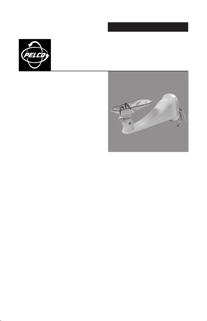
EM3512 Feedthrough
Wall Mount for EH3512 Series
®
24 VAC Enclosures
C268M-B (8/05)
Page 2

IMPORTANT SAFEGUARDS AND WARNINGS
Prior to installation and use of this product, the following WARNINGS should be observed.
1. Read these instructions.
2. Keep these instructions.
3. Heed all warnings.
4. Follow all instructions.
5. Do not block any ventilation openings. Install in accordance with the manufacturer’s
instructions.
6. Do not install near any heat sources such as radiators, heat registers, stoves, or other
apparatus (including amplifiers) that produce heat.
7. Only use attachments/accessories specified by the manufacturer.
8. Use only with the cart, stand, tripod, bracket, or table specified by the manufacturer, or sold
with the apparatus. When a cart is used, use caution when moving the cart/apparatus
combination to avoid injury from tip-over.
9. Refer all servicing to qualified service personnel. Servicing is required when the apparatus
has been damaged in any way, such as when the power supply cord or plug is damaged,
liquid has been spilled or objects have fallen into the apparatus, the apparatus has been
exposed to rain or moisture, the apparatus does not operate normally, or the apparatus has
been dropped.
10. To reduce the risk of shock, do not perform any servicing other than that contained in the
operating instructions unless you are qualified to do so.
11. Unless the unit meets NEMA Type 3, 3R, 3S, 4, 4X, 6, or 6P standards, it is designed for
indoor use only and must not be installed where exposed to rain and moisture.
12. Only use parts recommended by Pelco.
13. The installation methods and materials should be capable of supporting four times the weight
of the mount, enclosure, and camera and lens combination.
14. Use stainless steel hardware to fasten the enclosure to outdoor surfaces.
15. To prevent water leakage when installing a mount outdoors, apply sealant around the bolt
holes between the mount and the mounting surface.
16. Installation should be done only by qualified personnel and conform to all local codes.
17. Only EH3512 enclosures that use 24 VAC can be installed on the EM3512.
The product and/or manual may bear the following marks:
This symbol indicates that dangerous voltage constituting a risk of electric shock is
present within this unit.
This symbol indicates that there are important operating and maintenance instructions
in the literature accompanying this unit.
Please thoroughly familiarize yourself with the information in this manual prior to installation and
operation.
2 C268M-B (8/05)
Page 3

DESCRIPTION
The EM3512 Feedthrough Wall Mount provides an attractive mount for the following EH3512
enclosures that use 24 VAC power:
EH3512 enclosure when a 24 VAC camera is installed
EH3512-2 enclosure
EH3512-2HD enclosure
Video and power wiring are pre-installed and concealed within the mount.
NOTE: The EM3512 mount cannot be used with the EH3508 Series and EH3515 Series enclosures.
C268M-B (8/05) 3
Page 4
INSTALLATION
The following parts are supplied:
EM3512 mount
5/32-inch hex wrench
Two 1/4-20 x 5/8-inch Phillips screws
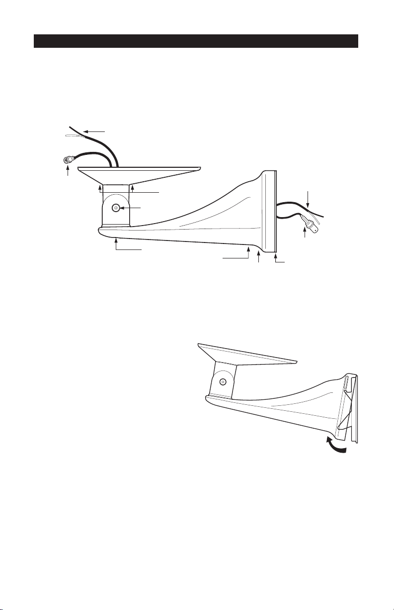
24 VAC POWER WIRING
FEMALE BNC
CONNECTOR
INSTALL THE WALL PLATE
SCREW HOLES TO
ATTACH EH3512
TILT ADJUSTING
SCREW
PAN ADJUSTING
SCREW
CONDUIT
FITTING
WALL PLATE
FASTENING
SCREW
Figure 1. EM3512 Feedthrough Wall Mount
24 VAC POWER WIRING
MALE BNC
CONNECTOR
WALL PLATE
1. Use the supplied 5/32-inch hex
wrench to remove the wall plate
fastening screw on the bottom, rear
of the mount, and then rethread the
screw a couple of turns (refer to
Figure 1). Remove the wall plate by
prying out the bottom of the plate
(refer to Figure 2).
2. Attach the wall plate to a wall,
electrical box, PA3512 Pole Mount
Adapter, or CM3512 Corner Mount
Adapter.
Figure 2. Removing Mount from Wall Plate
Refer to Table A for recommended minimal hardware requirements when attaching the wall plate
to a wall or electrical box. Hardware is supplied with the pole and corner mount adapters for
attaching the wall plate.
4 C268M-B (8/05)
Page 5

Table A. Minimum Hardware Requirements
Mount Recommended Mounting Surface Recommended Hardware
Wall Solid Concrete* Four 1/4 x 13/4-inch strike anchors
Wall board/2x4’s Two 1/4 x 2-inch lag bolts (bolts must
be attached to stud)
Plywood (3/4-inch construction grade) Four 1/4 x 2-inch lag bolts
Electrical Box Wall stud Hardware sufficient to penetrate
stud 1 inch
*Recommended strength of concrete is 3600 psi or 25 Mpa.
Concrete Wall
To mount to a concrete wall (refer to Figure 3):
a. Use the wall plate as a template to mark the four mounting holes in the wall, and then
prepare the holes.
b. Fasten the wall plate with hardware recommended in Table A. Make sure the wall plate is
oriented properly; TOP is written on the gasket on the back of the wall plate.
Wall Board
To mount to a surface with wall board (refer to Figure 3):
WARNING: Do not fasten the wall plate to the wall board only as it will not support the weight of
the mount and housing.
a. Use the wall plate as a template to mark two mounting holes where there is a stud in the
wall, and then prepare the holes.
b. Through the oblong hole in the middle of the wall plate, mark the center of the star cutout
in the gasket. Cut out a hole for video and power wiring.
c. Bring video and power
wiring through the hole in
the wall, and then through
the star cutout and oblong
hole in the wall plate.
d. Fasten the wall plate with
hardware recommended in
HOLES TO ATTACH TO
CONCRETE OR WOOD
STUD (ONLY TWO HOLES
REQUIRED FOR STUD);
USE 1/4-INCH DIAMETER
HARDWARE
NOTCHES TO
ATTACH TO
SINGLE-GANG
ELECTRICAL
BOX
Table A. Make sure the wall
plate is oriented properly;
TOP is written on the gasket
on the back of the wall plate.
Figure 3. Mounting the Wall Plate
C268M-B (8/05) 5
Page 6

Electrical Box
To mount to an electrical box (refer to Figure 3):
a. Fasten the electrical box to a wall stud with hardware recommended in Table A.
b. Bring video and power wiring into the electrical box, and then through the star cutout and
oblong hole in the center of the wall plate.
c. Attach the wall plate to the electrical box. Make sure the wall plate is oriented properly;
TOP is written on the gasket on the back of the wall plate.
Mount Adapter
To mount to a CM3512 Corner Mount Adapter or PA3512 Pole Mount Adapter, install the wall plate
to the corner or pole mount adapter according to the instructions supplied with the adapter.
ATTACH ENCLOSURE
NOTE: If you prefer you can fasten the mount to the wall plate (refer to the next section) before
attaching the enclosure to the mount.
1. Remove the camera sled from the enclosure.
a. Loosen the screws that hold the camera sled in place.
b. Slide the sled forward so it can be lifted out over the screws.
c. Remove the sled.
2. Feed the video and power wires from the mount through the holes in the bottom of the
enclosure. Be careful not to bind or pinch the wires.
CAUTION: Do not pull on the pre-installed wires in the mount to reposition them. The wires will not
move and pulling on them may damage the wires
3. Place the housing on the mount, and attach the housing to the mount with the two 1/4-20 x
5/8-inch Phillips screws that are provided with the mount (refer to Figure 1).
6 C268M-B (8/05)
.
Page 7

FASTEN MOUNT TO WALL PLATE
WARNING: Make sure the pan and tilt adjusting screws are tight before attaching the mount to
the wall plate (refer to Figure 1). Otherwise, the housing could move on the mount and cause you to
lose control of the mount and housing.
Wall Plate Attached to Concrete Wall, CM3512, or PA3512
1. Remove the 1/2-inch (1.27 cm) conduit plug in the bottom of the mount (refer to Figure 1).
2. Thread the video cable and power wiring in the EM3512 through the conduit opening.
3. Hook the mount over the notch in the top of the wall plate, and push the mount into place on
the wall plate. Refer to Figure 4.
Figure 4. Attaching Mount to Wall Plate
4. Tighten the screw in the bottom of the mount to hold the mount securely to the wall plate.
5. Run video and power wiring through 1/2-inch conduit and make electrical connections.
6. Fasten the conduit in the hole in the bottom of the mount.
C268M-B (8/05) 7
Page 8

Wall Plate Attached to Wall or Electrical Box
1. Connect the video and power wiring.
2. Hook the mount over the notch in the top of the wall plate, and push the mount into place on
the wall plate. Refer to Figure 4.
3. Replace the screw in the bottom of the mount and tighten it to hold the mount securely to the
wall plate.
COMPLETE INSTALLATION
Refer to the EH3512 Installation/Operation Manual to complete the installation. Loosen the pan
and tilt adjusting screws on the mount to position the enclosure, and then retighten the screws.
Refer to Figure 1.
8 C268M-B (8/05)
Page 9

SPECIFICATIONS
MECHANICAL
Pan Adjustment: 320°
Tilt Adjustment: ±90°
Locking Method: Socket head cap screws that require 5/32-inch hex wrench
GENERAL
Environment: Indoor/outdoor
Construction: Aluminum
Finish: Gray polyester powder coat
Dimensions: 14.33 (L) x 3.57 (W) x 4.93 (H) inches (36.40 x 9.07 x 12.52 cm)
Weight: 1.95 lb (0.88 kg)
C268M-B (8/05) 9
Page 10

10 C268M-B (8/05)
Page 11

WARRANTY AND RETURN INFORMATION
WARRANTY
Pelco will repair or replace, without charge, any merchandise proved defective in material or workmanship for a period of one year after the date of shipment.
Exceptions to this warranty are as noted below:
• Five years on FT/FR8000 Series fiber optic products.
• Three years on Genex® Series products (multiplexers, server, and keyboard).
• Three years on Camclosure® and fixed camera models, except the CC3701H-2, CC3701H-2X, CC3751H-2, CC3651H-2X, MC3651H-2, and MC3651H-2X
camera models, which have a five-year warranty.
• Two years on standard motorized or fixed focal length lenses.
• Two years on Legacy®, CM6700/CM6800/CM9700 Series matrix, and DF5/DF8 Series fixed dome products.
• Two years on Spectra®, Esprit®, ExSite™, and PS20 scanners, including when used in continuous motion applications.
• Two years on Esprit® and WW5700 Series window wiper (excluding wiper blades).
• Eighteen months on DX Series digital video recorders, NVR300 Series network video recorders, and Endura™ Series distributed network-based video
products.
• One year (except video heads) on video cassette recorders (VCRs). Video heads will be covered for a period of six months.
• Six months on all pan and tilts, scanners or preset lenses used in continuous motion applications (that is, preset scan, tour and auto scan modes).
Pelco will warrant all replacement parts and repairs for 90 days from the date of Pelco shipment. All goods requiring warranty repair shall be sent freight
prepaid to Pelco, Clovis, California. Repairs made necessary by reason of misuse, alteration, normal wear, or accident are not covered under this warranty.
Pelco assumes no risk and shall be subject to no liability for damages or loss resulting from the specific use or application made of the Products. Pelco’s liability
for any claim, whether based on breach of contract, negligence, infringement of any rights of any party or product liability, relating to the Products shall not
exceed the price paid by the Dealer to Pelco for such Products. In no event will Pelco be liable for any special, incidental or consequential damages (including
loss of use, loss of profit and claims of third parties) however caused, whether by the negligence of Pelco or otherwise.
The above warranty provides the Dealer with specific legal rights. The Dealer may also have additional rights, which are subject to variation from state to
state.
If a warranty repair is required, the Dealer must contact Pelco at (800) 289-9100 or (559) 292-1981 to obtain a Repair Authorization number (RA), and provide
the following information:
1. Model and serial number
2. Date of shipment, P.O. number, Sales Order number, or Pelco invoice number
3. Details of the defect or problem
If there is a dispute regarding the warranty of a product which does not fall under the warranty conditions stated above, please include a written explanation
with the product when returned.
Method of return shipment shall be the same or equal to the method by which the item was received by Pelco.
RETURNS
In order to expedite parts returned to the factory for repair or credit, please call the factory at (800) 289-9100 or (559) 292-1981 to obtain an authorization
number (CA number if returned for credit, and RA number if returned for repair).
All merchandise returned for credit may be subject to a 20% restocking and refurbishing charge.
Goods returned for repair or credit should be clearly identified with the assigned CA or RA number and freight should be prepaid. Ship to the appropriate
address below.
If you are located within the continental U.S., Alaska, Hawaii or Puerto Rico, send goods to:
If you are located outside the continental U.S., Alaska, Hawaii or Puerto Rico and are instructed to return goods to the USA, you may do one of the following:
If the goods are to be sent by a COURIER SERVICE, send the goods to:
Service Department
Pelco
3500 Pelco Way
Clovis, CA 93612-5699
Pelco
3500 Pelco Way
Clovis, CA 93612-5699 USA
If the goods are to be sent by a FREIGHT FORWARDER, send the goods to:
Pelco c/o Expeditors
473 Eccles Avenue
South San Francisco, CA 94080 USA
Phone: 650-737-1700
Fax: 650-737-0933
REVISION HISTORY
Manual # Date Comments
C268M 11/02 Original version.
C268M-A 5/03 Added UL certifications and warnings.
C268M-B 8/05 Revised hex wrench and hex size of screws from 1/8-inch to 5/32-inch per ECO 05-11169.
C268M-B (8/05) 11
Page 12

®
World Headquarters
3500 Pelco Way
Clovis, California 93612 USA
USA & Canada
Tel: 800/289-9100
Fax: 800/289-9150
International
Tel: 1-559/292-1981
Fax: 1-559/348-1120
www.pelco.com
ISO9001
United States | Canada | United Kingdom | The Netherlands | Singapore | Spain | Scandinavia | France | Middle East
 Loading...