

Page 1
C1467M-A (3/00)
EH2200
Indoor Enclosure
®
3500 Pelco Way,
Clovis, CA 93612-5699
USA
In North America & Canada:
Tel (800) 289-9100
FAX (800) 289-9150
International Customers:
Tel +1 (559) 292-1981
FAX +1 (559) 348-1120
www.pelco.com
IMPORTANT SAFEGUARDS AND WARNINGS
Prior to installation and use of this product, the following WARNINGS should be observed.
1. Installation and servicing should only be done by qualified service personnel and conform
to all local codes.
2. Unless the unit is specifically marked as a NEMA Type 3, 3R, 3S, 4, 4X ,6 or 6P enclosure, it is designed for indoor use only and it must not be installed where exposed to rain
and moisture.
3. Only use replacement parts recommended by Pelco.
4. The installation method and materials should be capable to supporting four times the
weight of the enclosure, camera and lens combination.
The product and/or manual may bear the following marks:
This symbol indicates that dangerous voltage constituting a risk of
electric shock is present within
this unit.
This symbol indicates that there
are important operating and maintenance instructions in the literature accompanying this unit.
Please thoroughly familiarize yourself with the information in this manual prior to installation
and operation.
CAUTION:
RISK OF ELECTRIC SHOCK.
DO NOT OPEN.
DESCRIPTION
The EH2200 is a medium security enclosure that mounts to the corner of two walls. It can be
installed flush against the ceiling or mid-wall in high ceiling applications. The enclosure’s compact design is perfect for small cameras. Total camera and lens length must not exceed 5
inches (12.70 cm).
INSTALLATION
The following items are supplied:
1 5/32-inch hex key
1 Camera mounting screw, 1/4-20 x .375-inch, Phillips, pan head
Page 2
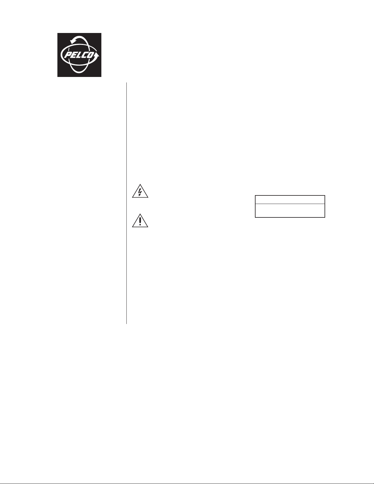
BRACKET
COVER
TILT TABLE
Figure 1. EH2200 Exploded Assembly
ADJUSTABLE
TOP MOUNT
KNOCKOUT-1/2-INCH
CONDUIT
TAMPER-RESISTANT
SCREW
HEX KEY
To install the EH2200 refer to Figure 1 and
do the following:
1. Ensure that the mounting surface is
capable of supporting four times the
weight of the enclosure, camera and
lens.
2. Remove the cover by loosening the
tamper-resistant screw with the
enclosed hex key.
3. Remove the tilt table assembly.
4. Determine the mounting location. Use
the mounting bracket as a template and
mark the four fastener positions onto
the mounting surface.
5. Remove the appropriate knockouts
needed for camera power and video
wiring. Pull wiring into the enclosure.
6. Fasten the mounting bracket to the
surface. Secure with a recommended
minimum of 1/4-20 screws (not
supplied).
7. Reinstall the tilt table assembly.
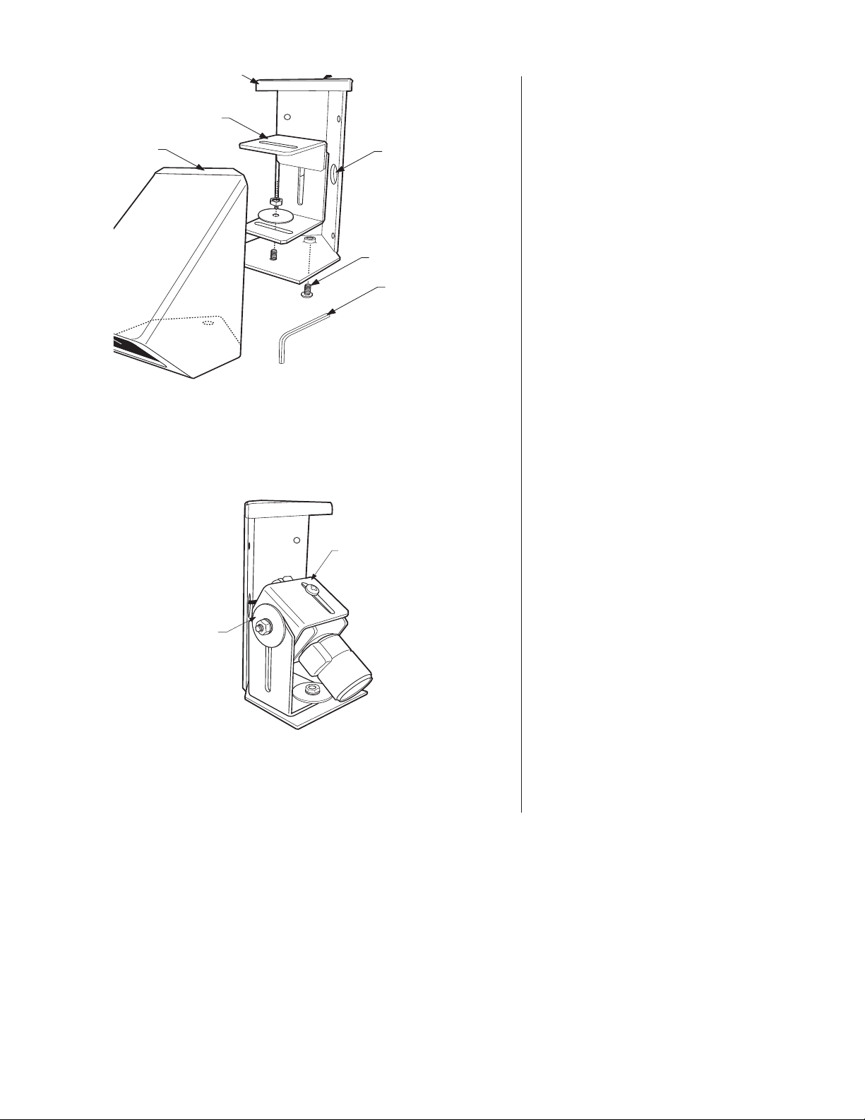
8. Mount the camera and lens to the top
or bottom of the tilt table with the
1/4-20 x .375-inch screw. Extend the
lens to its maximum length before installing. This will ensure that the lens
has enough clearance and will not hit
the window during focusing. Refer to
Figure 2.
ADJUSTABLE
MOUNTING
BRACKET
Camera and lens mounting position can vary. Illustration shows top of camera
mounted to the tilt table. Bottom of camera also can be mounted to the tilt table.
Figure 2. Camera Mounting
9. Replace the enclosure cover. Check
that all components clear the cover and
that the camera angle and lens
adjustments are satisfactory. When all
adjustments are complete, secure the
cover.
Page 3

MAINTENANCE
Clean the window regularly to help maintain picture clarity. Use a soft cloth and a mild
nonabrasive detergent. To order replacement parts, refer to Table A.
Table A. Mechanical Parts List
Qty Description Part Number
1 Mounting bracket weld assembly EH22001001WA
1 Cover weld assembly EH22001000WA
1 Window EH220010000
1 Button head tamper-proof screw ZH8-32X.500TSS
2 4-40 hex nut ZH4-40NUTSH
2 Flat washer ZH125X312X32S
1Tilt table support leg EH22004003COMP
1Tilt table EH22004004COMP
2 1/4-20 hex nut ZH1/4-20NUTCH
2 .25-inch split lock washer ZH1/4LWSSL
2 Fender washer ZH255X1.50X62
3.88
(9.84)
1.75
(4.44)
NOTE: VALUES IN PARENTHESES ARE CENTIMETERS;
ALL OTHERS ARE IN INCHES.
4.50 (11.43)
6.75 (17.15)
2.25
(5.72)
1.63 (4.14)
5.50
(13.97)
5.00
(12.70)
7.13
(18.11)
SPECIFICATIONS
MECHANICAL
Camera Mounting: Adjustable tilt table
Maximum
Camera/Lens Size: Accommodates
Viewing Window: .187-inch (4.76 mm)
Window Viewing Area: 3.00 (W) x 1.88 (H)
Cable Entry Holes: .875-inch diameter
Enclosure Mounting: Four .25-inch diam-
GENERAL
Construction: .125-inch (3.175
Finish: Gray polyester pow-
camera/lens combinations (including
BNC connector) up
to: 5.0 (L) x 4.0 (W)
x 4.0 (H) inches
(12.7 x 10.16 x
10.16 cm)
thick LEXAN
®
inches (7.62 x 4.78
cm)
access through rear
walls and top
eter holes on protected rear surfaces
mm) thick aluminum
der coat
Figure 3. EH2200 Dimension Drawing
Dimensions: See Figure 3
Environment: Indoor
Unit Weight: 2.0 lb (0.91 kg)
Page 4

PRODUCT WARRANTY AND RETURN INFORMATION
WARRANTY
Pelco will repair or replace, without charge, any merchandise proved defective in material or
workmanship for a period of one year after the date of shipment.
Exceptions to this warranty are as noted below:
• Five years on FT/FR8000 Series fiber optic products.
®
• Three years on Genex
• Three years on Camclosure® and fixed camera models, except the CC3701H-2,
CC3701H-2X, CC3751H-2, CC3651H-2X, MC3651H-2, and MC3651H-2X camera models,
which have a five-year warranty.
•Two years on standard motorized or fixed focal length lenses.
•Two years on Legacy
fixed dome products.
•Two years on Spectra
continuous motion applications.
•Two years on Esprit
• Eighteen months on DX Series digital video recorders, NVR300 Series network video
recorders, and Endura
• One year (except video heads) on video cassette recorders (VCRs). Video heads will be
covered for a period of six months.
• Six months on all pan and tilts, scanners or preset lenses used in continuous motion
applications (that is, preset scan, tour and auto scan modes).
Pelco will warrant all replacement parts and repairs for 90 days from the date of Pelco
shipment. All goods requiring warranty repair shall be sent freight prepaid to Pelco, Clovis,
California. Repairs made necessary by reason of misuse, alteration, normal wear, or accident
are not covered under this warranty.
Pelco assumes no risk and shall be subject to no liability for damages or loss resulting from
the specific use or application made of the Products. Pelco’s liability for any claim, whether
based on breach of contract, negligence, infringement of any rights of any party or product
liability, relating to the Products shall not exceed the price paid by the Dealer to Pelco for
such Products. In no event will Pelco be liable for any special, incidental or consequential
damages (including loss of use, loss of profit and claims of third parties) however caused,
whether by the negligence of Pelco or otherwise.
The above warranty provides the Dealer with specific legal rights. The Dealer may also have
additional rights, which are subject to variation from state to state.
Series products (multiplexers, server, and keyboard).
®
, CM6700/CM6800/CM9700 Series matrix, and DF5/DF8 Series
®
, Esprit®, ExSite™, and PS20 scanners, including when used in
®
and WW5700 Series window wiper (excluding wiper blades).
™
Series distributed network-based video products.
If a warranty repair is required, the Dealer must contact Pelco at (800) 289-9100 or
(559) 292-1981 to obtain a Repair Authorization number (RA), and provide the following
information:
1. Model and serial number
2. Date of shipment, P.O. number, Sales Order number, or Pelco invoice number
3. Details of the defect or problem
If there is a dispute regarding the warranty of a product which does not fall under the
warranty conditions stated above, please include a written explanation with the product
when returned.
Method of return shipment shall be the same or equal to the method by which the item was
received by Pelco.
RETURNS
In order to expedite parts returned to the factory for repair or credit, please call the factory at
(800) 289-9100 or (559) 292-1981 to obtain an authorization number (CA number if returned
for credit, and RA number if returned for repair).
All merchandise returned for credit may be subject to a 20% restocking and refurbishing
charge.
Goods returned for repair or credit should be clearly identified with the assigned CA or RA
number and freight should be prepaid. Ship to the appropriate address below.
If you are located within the continental U.S., Alaska, Hawaii or Puerto Rico, send goods to:
Service Department
Pelco
3500 Pelco Way
Clovis, CA 93612-5699
If you are located outside the continental U.S., Alaska, Hawaii or Puerto Rico and are
instructed to return goods to the USA, you may do one of the following:
If the goods are to be sent by a COURIER SERVICE, send the goods to:
Pelco
3500 Pelco Way
Clovis, CA 93612-5699 USA
If the goods are to be sent by a FREIGHT FORWARDER, send the goods to:
Pelco c/o Expeditors
473 Eccles Avenue
South San Francisco, CA 94080 USA
Phone: 650-737-1700
Fax: 650-737-0933
REVISION HISTORY
Manual # Date Comments
C1467M 7/97 Original version.
C1467M-A 3/00 Added instructions for mounting camera into the enclosure. Updated manual to new format.
® Pelco, the Pelco logo, Spectra, Genex, Legacy, and PelcoVision are registered trademarks of Pelco. ™Esprit and Camclosure are trademarks of Pelco.
® LEXAN is a registered trademark of the General Electric Company. © Copyright 2000, Pelco. All rights reserved.
 Loading...