


INSTALLATION
EH16 Series IP-Enabled Enclosures
EH16 Enclosure with EM16 Mount
C3489M-B (3/14)

Contents
Important Safety Instructions . . . . . . . . . . . . . . . . . . . . . . . . . . . . . . . . . . . . . . . . . . . . . . . . . . . . . . . . . . . . . . . . . . . . . . . . . . . . . . . . . . . . . . . . . . . . 3
Description. . . . . . . . . . . . . . . . . . . . . . . . . . . . . . . . . . . . . . . . . . . . . . . . . . . . . . . . . . . . . . . . . . . . . . . . . . . . . . . . . . . . . . . . . . . . . . . . . . . . . . . . . . . 4
Package Contents . . . . . . . . . . . . . . . . . . . . . . . . . . . . . . . . . . . . . . . . . . . . . . . . . . . . . . . . . . . . . . . . . . . . . . . . . . . . . . . . . . . . . . . . . . . . . . . . . 5
User-Supplied Tools . . . . . . . . . . . . . . . . . . . . . . . . . . . . . . . . . . . . . . . . . . . . . . . . . . . . . . . . . . . . . . . . . . . . . . . . . . . . . . . . . . . . . . . . . . . . . . . 5
Installation . . . . . . . . . . . . . . . . . . . . . . . . . . . . . . . . . . . . . . . . . . . . . . . . . . . . . . . . . . . . . . . . . . . . . . . . . . . . . . . . . . . . . . . . . . . . . . . . . . . . . . . . . . . 6
Preparing the Enclosure . . . . . . . . . . . . . . . . . . . . . . . . . . . . . . . . . . . . . . . . . . . . . . . . . . . . . . . . . . . . . . . . . . . . . . . . . . . . . . . . . . . . . . . . . . . . 6
Installing the Mount . . . . . . . . . . . . . . . . . . . . . . . . . . . . . . . . . . . . . . . . . . . . . . . . . . . . . . . . . . . . . . . . . . . . . . . . . . . . . . . . . . . . . . . . . . . . . . . 7
Installing the Camera in the Enclosure. . . . . . . . . . . . . . . . . . . . . . . . . . . . . . . . . . . . . . . . . . . . . . . . . . . . . . . . . . . . . . . . . . . . . . . . . . . . . . . . . 8
Installing the Sun Shroud . . . . . . . . . . . . . . . . . . . . . . . . . . . . . . . . . . . . . . . . . . . . . . . . . . . . . . . . . . . . . . . . . . . . . . . . . . . . . . . . . . . . . . . . . . . 8
Installing Lanyards . . . . . . . . . . . . . . . . . . . . . . . . . . . . . . . . . . . . . . . . . . . . . . . . . . . . . . . . . . . . . . . . . . . . . . . . . . . . . . . . . . . . . . . . . . . . . . . . 8
Wiring . . . . . . . . . . . . . . . . . . . . . . . . . . . . . . . . . . . . . . . . . . . . . . . . . . . . . . . . . . . . . . . . . . . . . . . . . . . . . . . . . . . . . . . . . . . . . . . . . . . . . . . . . . . . . . 9
Maintenance . . . . . . . . . . . . . . . . . . . . . . . . . . . . . . . . . . . . . . . . . . . . . . . . . . . . . . . . . . . . . . . . . . . . . . . . . . . . . . . . . . . . . . . . . . . . . . . . . . . . . . . . 12
Specifications . . . . . . . . . . . . . . . . . . . . . . . . . . . . . . . . . . . . . . . . . . . . . . . . . . . . . . . . . . . . . . . . . . . . . . . . . . . . . . . . . . . . . . . . . . . . . . . . . . . . . . . 13
2 C3489M-B (3/14)
Important Safety Instructions
CAUTION:
RISK OF ELECTRIC SHOCK.
DO NOT OPEN.
1. Read these instructions.
2. Keep these instructions.
3. Heed all warnings.
4. Follow all instructions.
5. Clean only with dry cloth.
6. Do not block any ventilation openings. Install in accordance with the manufacturer’s instructions.
7. Do not install near any heat sources such as radiators, heat registers, stoves, or other apparatus (including amplifiers) that produce heat.
8. Only use attachments/accessories specified by the manufacturer.
9. Refer all servicing to qualified service personnel. Servicing is required when the apparatus has been damaged in any way, such as powersupply cord or plug is damaged, liquid has been spilled or objects have fallen into the apparatus, the apparatus has been exposed to rain or
moisture, does not operate normally, or has been dropped.
10. Installation should be done only by qualified personnel and conform to all local codes.
11. Unless the unit is specifically marked as a NEMA Type 3, 3R, 3S, 4, 4X, 6, or 6P enclosure, it is designed for indoor use only and it must not
be installed where exposed to rain and moisture.
12. Use only installation methods and materials capable of supporting four times the maximum specified load.
13. Use stainless steel hardware to fasten the mount to outdoor surfaces.
14. An all-pole main switch with a contact separation of at least 3 mm in each pole shall be incorporated in the electrical installation of the
building.
15. A readily accessible disconnect device shall be incorporated in the building installation wiring.
CAUTION: These servicing instructions are for use by qualified service personnel only. To reduce the risk of electric shock do not perform any
servicing other that contained in the operating instructions unless you are qualified to do so.
Only use replacement parts recommended by Pelco.
After replacement/repair of this unit’s electrical components, conduct a resistance measurement between the line and exposed parts to verify
the exposed parts have not been connected to the line circuitry.
The product and/or manual may bear the following marks:
This symbol indicates that dangerous voltage constituting a risk of electric shock is present
within this unit.
This symbol indicates that there are important operating and maintenance instructions in
the literature accompanying this unit.
C3489M-B (3/14) 3

Description
IP-enabled, indoor/outdoor, EH16 Series enclosures are designed for use with small- to medium-sized analog and IP cameras. They accommodate
both fixed and variable focal length lenses (with or without auto iris operation). They can be mounted to a wall using either the Pelco EM16
(feedthrough wall mount) or EM1450 (non-feedthrough wall mount), or any light to medium duty mount.
The tethered, detachable enclosure lid provides easy access during installation and when camera and lens adjustments are necessary. Cabling
for power and video is brought into the enclosure through two adjustable glands (PG9 and PG11) on the bottom of the enclosure, allowing for
easy installation.
Factory-installed options include a heater and blower with a 24 VAC camera power supply and sun shroud. The enclosures can also be ordered
from the factory with 24 VAC or IEEE802.3at power over ethernet (PoE) enclosure input voltage, 802.3af-compatible camera power, and
appropriate heater and blower power.
Model Description
EH16 Basic enclosure, indoor/outdoor, included in all EH16 models.
EH16MT Includes an additional EM16 feedthrough wall mount.
EH16MTS Additional features include an EM16 feedthrough wall mount and sun shroud.
EH16-2 Additional features include a heater/blower and 24 VAC camera power; 10 W enclosure power consumption*.
EH16-2MT Additional features include a heater/blower, 24 VAC camera power, and an EM16 feedthrough wall mount; 10 W
EH16-2MTS Additional features include a heater/blower, 24 VAC camera power, an EM16 feedthrough wall mount, and an SS16
EH16-3 Additional features include a heater/blower and 24 VAC camera power (includes a 4-inch wire tie); 10 W enclosure
EH16-3MT Additional features include a heater/blower, 24 VAC camera power, and an EM16 feedthrough wall mount (includes a
EH16-3MTS Additional features include a heater/blower, 24 VAC camera power, an EM16 feedthrough wall mount (includes a
EH16-2P Additional features include a heater/blower and 802.3af-compatible PoE camera power; 10 W enclosure power
EH16-2PMT Additional features include a heater/blower, 802.3af-compatible PoE camera power, and an EM16 feedthrough wall
EH16-2PMTS Additional features include a heater/blower, 802.3af-compatible PoE camera power, an EM16 feedthrough wall
EH16-8P Additional features include PoE IEEE802.3at input to provide heater/blower power and 802.3af-compatible camera
EH16-8PMT Additional features include PoE IEEE802.3at input to provide heater/blower power and 802.3af-compatible camera
EH16-8PMTS Additional features include PoE IEEE802.3at input to provide heater/blower power and 802.3af-compatible camera
Table A. Indoor/Outdoor Enclosure Models
enclosure power consumption*.
sun shroud; 10 W enclosure power consumption*.
power consumption*; 25 W maximum power consumption capacity.
4-inch wire tie); 10 W enclosure power consumption*; 25 W maximum power consumption capacity.
4-inch wire tie), and an SS16 sun shroud; 10 W enclosure power consumption*; 25 W maximum power consumption
capacity.
consumption*; 25 W maximum power consumption capacity.
mount; 10 W enclosure power consumption*; 25 W maximum power consumption capacity.
mount, and an SS16 sun shroud; 10 W enclosure power consumption*; 25 W maximum power consumption capacity.
power; 10 W enclosure power consumption*; 25 W maximum power consumption capacity.
power, and an EM16 feedthrough wall mount; 10 W enclosure power consumption*; 25 W maximum power
consumption capacity.
power, an EM16 feedthrough wall mount, and an SS16 sun shroud; 10 W enclosure power consumption*; 25 W
maximum power consumption capacity.
*Enclosure power consumption does not include camera wattage.
4 C3489M-B (3/14)

PACKAGE CONTENTS
Qty Description
1 EH16 Series enclosure
1 Installation manual
1 Screw, 1/4-20 x 3/8-inch, Phillips
1 Washer, 1/4-inch split lock
2 Screws, M6 x 1.0 P x 12 mm, T30 Torx head
1 Gland and nut, PG9 cable
1 Gland and nut, PG11 cable
1 Wire tie, 4-inch (EH16-3 model only)
1 Cat5 PoE cable with RJ-45 connector
1 RJ-45 connector for data or data/PoE connections (EH16-2P and EH16-8P models only)
1 EM16 mount (optional)
1 SS16 sun shroud (optional)
USER-SUPPLIED TOOLS
A T30 Torx driver and a Phillips screwdriver are required for installation but are not included. A flat-head screwdriver might also be needed for all
models except the EH16 and EH16MT. A Phillips screwdriver, flat-head screwdriver, or 1/4-inch nut driver is needed for the EH16-3 only. The
T30 Torx driver is needed to secure the enclosure to all mounts. It is also needed to open and close the enclosure and to secure the pan/tilt
(swivel head) on the EM16 mount.
C3489M-B (3/14) 5
Installation
Install your camera and EH16 enclosure according to the following procedures. Use the supplied tools provided in the product box and other
tools as suggested in the User-Supplied Tools on page 5 for your model. Installation procedures for optional mount and sun shroud accessories
are also described.
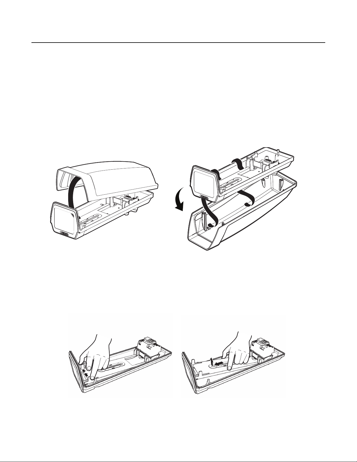
PREPARING THE ENCLOSURE
1. Use a T30 Torx driver (not supplied) to loosen the three 10-24 x 0.75-inch T30 Torx-head screws (factory installed) that are located on the
enclosure base.
2. Lift up and remove the lid.
NOTE: The gasket can come loose when the lid is removed. Be sure to properly reseat the gasket when closing the lid, if necessary.
3. Hang the lid from the side of the enclosure base by the lanyards that are factory-installed.
NOTE: Lanyards can be removed and repositioned. Refer to Installing Lanyards on page 8 for attachment instructions.
Figure 1. Removing the Lid with Lanyards Attached
4. Remove the camera sled from the enclosure rail:
a. Locate the two plastic tabs near the front window that hold the camera sled in place.
b. Squeeze the tabs inward.
c. Pull up and slide the sled forward.
d. Remove the sled.
Figure 2. Removing the Sled
6 C3489M-B (3/14)

5. Remove the parts bag. This includes the screws, split washers, glands, and nuts.
6. Remove the glands and nuts from the parts bag.
7. Prepare the enclosure for wiring using one of the following options:
• Without conduit (for example, the EM16 mount): Install and tighten the glands and nuts in the bottom of the enclosure with the
gland threads pointed toward the inside of the enclosure. Refer to Table C on page 12 for allowable cable diameters for the glands. The
PG11 gland might not accommodate RG11 coaxial cable because the coaxial diameter might be larger than the 1.00 cm (0.395-inch)
diameter of the gland.
• With conduit: Remove the board assembly before drilling the hole, and then use a step drill to drill the larger hole to
2.22 cm (0.875-inch) for 1/2-inch conduit.
• If ground connection is required: Connect the ground wire that is in front of the PC board to the ground boss and screw located on
the bottom of the enclosure. Refer to Figure 6 on page 11 for an illustration of the ground boss location. For EH16-3, pass the zip tie
(supplied) through the hole in the PC board cover.
INSTALLING THE MOUNT
Install the mount according to one of the following procedures that is relevant for your mount type. For all mount options, be sure to route
coaxial cable and wiring along the sides of the enclosure to avoid heating problems. Maintain separation between 230 VAC, 24 VAC, and
video wiring.
EM16 MOUNT
1. Attach the EM16 mount to the wall:
a. Use the mount as a template to mark and drill holes in the mounting surface.
b. Pull the required cables from the wall through the mount. If wiring with conduit, use a step drill to drill a 2.22 cm (0.875-inch) hole in
one of the three knockout locations for 1/2-inch conduit. Knockout centering indicators (small circular depressions) are located on
the side and bottom of the mount arm. Refer to Table B on page 11 to determine the size of the power wire needed. Refer to
Table D on page 12 to determine the type of video coaxial cable needed (if no PoE).
c. Fasten the mount to the wall using a minimum of two flat washers (not supplied) and two 6 mm (1/4-inch) bolts (not supplied).
WARNINGS:
• If you install the mount outdoors, rainwater could leak through the mounting bolt holes and damage the wall. To prevent
water damage, seal the bolt holes with an appropriate sealant. Apply the sealant around the bolt holes between the mount
and the mounting surface.
• Use fasteners of a suitable size, and make sure the mounting surface can support the combined weight of the mount and
camera/enclosure.
d. Pull the cables through the glands in the enclosure. Tighten the glands around the cables.
2. Attach the enclosure to the EM16 mount using the threaded mounting holes in the bottom of the enclosure:
a. Thread the two M6 Torx screws (supplied) into the enclosure mounting holes until there is resistance. The M6 Torx screws have a
locking patch that resists loosening.
b. Pull the cables through the glands until the glands are two to three finger-widths from touching the EM16 mount. Tighten the glands.
c. Terminate installation wires as needed.
d. Attach the enclosure to the mount by inserting the heads of the M6 Torx screws through the keyholes of the mount. Slide the enclosure
to seat the M6 Torx screws in the slots and tighten the screws to secure the enclosure.
MOUNTS OTHER THAN EM16
1. Install the mount according to the specific installation instructions supplied with the mount.
2. Pull the required cables through the glands or conduit on the bottom of the enclosure. Refer to Table B on page 11 to determine the size and
distance of power wire needed for 24 VAC. Refer to Table D on page 12 to determine the type of video coaxial cable needed (if no PoE).
C3489M-B (3/14) 7
INSTALLING THE CAMERA IN THE ENCLOSURE
1. Adjust the glands for a tight fit around the cables. If you are wiring the enclosure using a conduit, install the fittings to connect the conduit
to the enclosure.
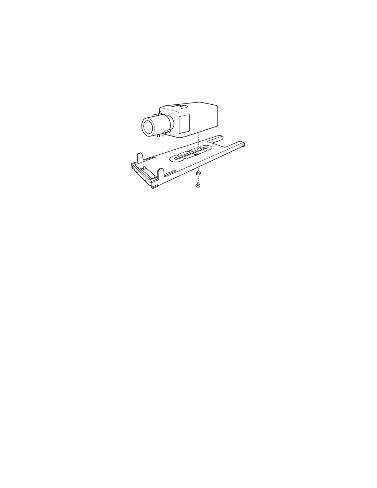
2. Attach the camera:
a. Attach the camera to the sled with the 1/4-20 x 3/8-inch Phillips screw (supplied) and the 1/4-inch split lock washer (refer to Figure 3
on page 8).
b. Align the front of the lens with the front edge of the sled.
c. Tighten the screw, and then place the sled back into the enclosure.
Figure 3. Attaching the Camera to the Sled
3. Connect video and power to the enclosure and camera. For PoE models, refer to Figure 4 on page 9. For EH16-2 and EH16-3 models, refer to
Figure 6 on page 11. For EH16-3 models, secure the input power wires to the PCB cover using the zip tie (supplied).
4. Adjust the camera focal length and focus, if necessary.
5. Position the enclosure lid and close it. Lanyards, if not installed, must be installed at this step before securing the lid.
NOTE: The gasket can come loose when the lid is removed. Be sure to properly reseat the gasket when closing the lid, if necessary.
6. Tighten the factory-installed 10-24 x 0.75-inch T30 Torx-head screws using a T30 Torx driver (not supplied).
INSTALLING THE SUN SHROUD
The optional sun shroud fits over the top of the EH16 enclosure.
1. Position the front of the sun shroud above the front of the enclosure.
2. Press the sun shroud down and against the enclosure until the sun shroud snaps into place.
INSTALLING LANYARDS
Use the following procedure to install lanyards that have been removed or to relocate lanyards to the opposite side of the enclosure lid. Lanyards
must be installed before the lid has been sealed on the enclosure (refer to step 5 in Installing the Camera in the Enclosure on page 8).
1. Attach the lanyards to the pins on either side of the enclosure base.
2. Stretch the lanyard around the inside of the lid to the opposite side and attach the free end of the lanyard to the pins in the lid (refer to
Figure 1 on page 6).
3. Confirm correct installation by viewing the lanyards though the viewing window. Properly installed lanyards will run from the pins on the
enclosure base around the inside of the enclosure lid to the pins on the opposite side of the lid.
8 C3489M-B (3/14)

Wiring
EH16-2P INPUTS AND OUTPUTS
OUTPUT TO CAMERA
PoE (802.3af COMPATIBLE)
AND DATA
24 VAC INPUT
HEATER CONNECTOR
(FACTORY-CONNECTED)
BLOWER CONNECTOR
(FACTORY-CONNECTED)
DATA INPUT
USER-SUPPLIED
CAT5 e CABLE
FROM SWITCH WITH
RJ-45 CONNECTOR
(SUPPLIED)
FACTORY-INSTAL LE D
CAT5 e PATCH CABLE
Figure 4. EH16-2P PoE Wiring
C3489M-B (3/14) 9
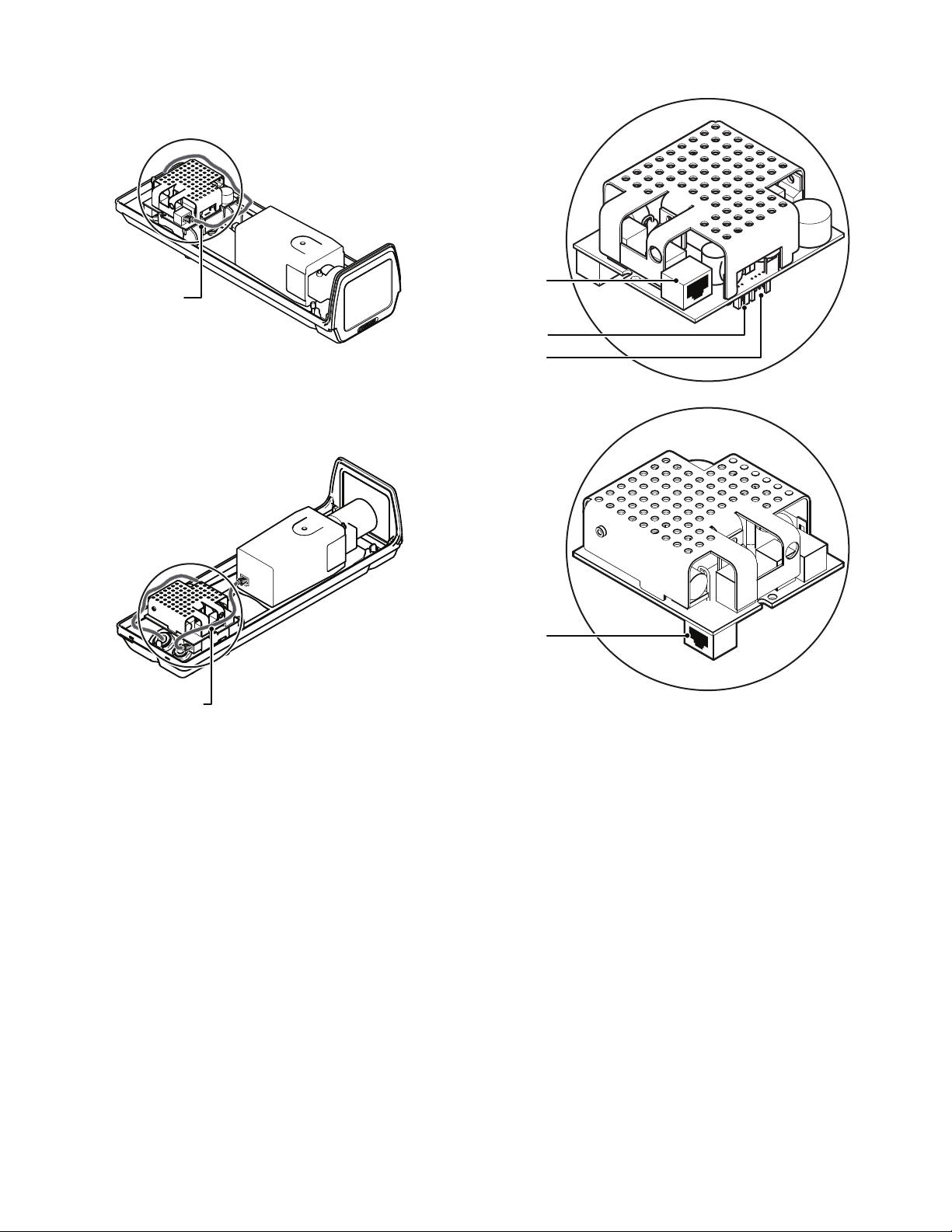
HEATER CONNECTOR
(FACTORY-CONNECTED)
BLOWER CONNECTOR
(FACTORY-CONNECTED)
EH16-8P INPUTS AND OUTPUTS
PoE 802.3at
AND DATA INPUT
OUTPUT TO CAMERA
PoE (802.3af COMPATIBLE)
AND DATA
USER-SUPPLIED
CAT5 e CABLE
FROM SWITCH WITH
RJ-45 CONNECTOR
(SUPPLIED)
FACTORY-INSTAL LE D
CAT5 e PATCH CABLE
Figure 5. EH16-8P PoE Wiring
10 C3489M-B (3/14)

AC IN
HI NT HI NT
AC OUT
HI LOW
24 VAC
LOW HI
AC AC
EH16-2 INPUTS AND OUTPUTS
EH16-3 INPUTS AND OUTPUTS
24 VAC CAMERA OUTPUT
HIGH
INPUT, AC HIGH
INPUT, AC LOW (NEUTRAL)
230 VAC CAMERA OUTPUT, LOW (NEUTRAL)
230 VAC OUTPUT, HIGH
24 VAC CAMERA OUTPUT
LOW
CAMERA OUTPUT, AC LOW (NEUTRAL)
CAMERA OUTPUT, AC HIGH
INPUT, AC HIGH
INPUT, AC LOW (NEUTRAL)
0 - GROUND BOSS
ZIP TIE HERE
CAMERACAMERA
GROUND
BOSS
Figure 6. EH16-2 and EH 16-3 Wiring
C3489M-B (3/14) 11
Table B describes the recommended maximum distances for 24 VAC applications, which are calculated with a 10 percent voltage drop.
Ten percent is generally the maximum allowable voltage drop for AC-powered devices. For example, an enclosure that requires 30 VA and is
installed 28 m (94 ft) from the transformer would require a minimum wire gauge of 20 AWG.
Table B. 24 VAC Wiring Sizes and Distances
Wire Gauge
Total VA 20 AWG (0.5 mm
2
) 18 AWG (1.0 mm2) 16 AWG (1.5 mm2) 14 AWG (2.5 mm2)
10 86 m (283 ft) 137 m (451 ft) 218 m (716 ft) 348 m (1142 ft)
20 42 m (141 ft) 68 m (225 ft) 109 m (358 ft) 174 m (571 ft)
30 28 m (94 ft) 45 m (150 ft) 73 m (238 ft) 115 m (380 ft)
40 21 m (70 ft) 34 m (112 ft) 54 m (179 ft) 86 m (285 ft)
50 17 m (56 ft) 27 m (90 ft) 43 m (143 ft) 69 m (228 ft)
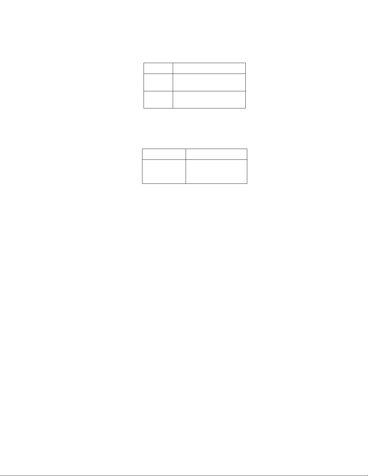
Table C describes the allowable cable diameters for the PG9 and PG11 glands. A conduit must be used if the cable diameter is greater than
1.00 cm (0.395-inch). RG11 coaxial might be greater than 1.00 cm (0.395-inch).
Table C. Allowable Cable Diameter
Gland Cable Diameter
Table D describes the recommended maximum distances and minimum cable requirements for RG59/U, RG6/U, RG11/U video coaxial cables.
Maintenance
Clean the window regularly to maintain picture clarity. Use a soft cloth and a mild, nonabrasive detergent and water.
PG9
PG11
Table D. Video Coaxial Cable Wiring Distance
Cable Type* Maximum Distance
RG59/U
RG11/U
*Minimum Cable Requirements:
75-ohm impedance
All-copper center conductor
All-copper braided shield with 95% braid coverage
0.46 cm (0.181-inch) to
0.79 (0.312-inch)
0.58 cm (0.230-inch) to
1.00 cm (0.395-inch)
RG6/U
229 m (750 ft)
305 m (1,000 ft)
457 m (1,500 ft)
12 C3489M-B (3/14)

Specifications
MECHANICAL
Camera Mounting Single slot for adjustable camera positioning on snap-in camera sled
Camera and Lens Size Accepts camera and lens combinations (including BNC connector) up to 22.86 x 7.92 x 7.62 cm
Viewing Window 0.30 cm (0.118-inch) thick, high optic grade, scratch-resistant Lexan
Viewing Area 7.14 x 6.27 cm (2.81" W x 2.47" H)
Cable Entry 1 x PG9 and 1 x PG11 compression glands on bottom
Maximum Cable Diameters
PG9 0.80 cm (0.312-inch)
PG11 1.00 cm (0.395-inch)
Cable Entry Holes 1 x 1.91 cm (0.750-inch) diameter and 1 x 1.60 cm (0.630-inch) diameter;
Lid Fastening 3 Torx-head T30 screws
ELECTRICAL
Input Power 24 VAC, IEEE802.3at, or 230 VAC
Input Voltage
PoE IEEE802.3at
24 VAC ±10% VAC
230 VAC ±10% VAC
GENERAL
Construction Die-cast aluminum
Finish Alodine with gray polyester powder coat
Environment Indoor/outdoor ambient temperature –30° to 60°C (–22° to 140°F)
Unit Length
Base 33.99 cm (13.38-inch)
Overall 36.55 cm (14.39-inch)
Unit Weight
EH16 1.13 kg (2.50 lb)
EH16-MT 1.42 kg (3.13 lb)
EH16-MTS 2.16 kg (4.76 lb)
EH16-2 1.16 kg (2.56 lb)
EH16-2MT 1.45 kg (3.19 lb)
EH16-2MTS 2.16 kg (4.76 lb)
EH16-3 1.16 kg (2.56 lb)
EH16-3MT 1.45 kg (3.19 lb)
EH16-3MTS 2.16 kg (4.76 lb)
EH16-2P 1.27 kg (2.80 lb)
EH16-2PMT 1.51 kg (3.43 lb)
EH16-2PMTS 2.27 kg (5.00 lb)
EH16-8P 1.22 kg (2.70 lb)
EH16-8PMT 1.47 kg (3.23 lb)
EH16-8PMTS 2.22 kg (4.90 lb)
(9.00" L x 3.12" W x 3.00" H)
™
1.91 cm (0.750-inch) hole will accept 1/2-inch NPT conduit fitting when enlarged to 2.22 cm (0.875-inch);
1.60 cm (0.630-inch) hole will accept 1/4-inch NPT conduit fitting
C3489M-B (3/14) 13
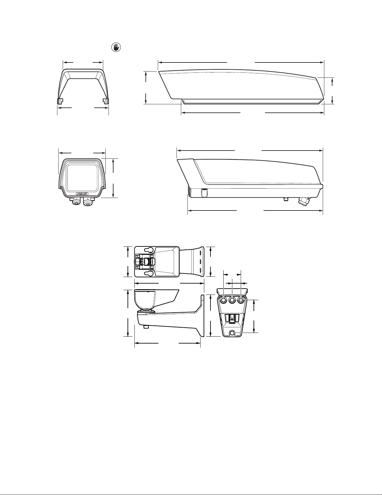
NOTE: VALUES IN PARENTHESES ARE INCHES; ALL OTHERS ARE CENTIMETERS.
9.65 (3.80)
12.55 (4.94)
35.56 (14.00)
40.67 (16.01)
6.71
(2.64)
8.31
(3.27)
11.35 (4.47)
9.60
(3.78)
36.55 (14.39)
33.99 (13.38)
Figure 7. SS16 Sun Shroud
Figure 8. EH16 Camera Enclosure
6.63
(2.61)
10.21
(4.02)
6.50
(2.56)
15.24 (6.00)
9.14
(3.60)
14.58 (5.74)
Figure 9. Optional EM16 Wall Mount
3.81
(1.50)
1.91
(0.75)
7.21
(2.84)
14 C3489M-B (3/14)

WARRANTY STATEMENT
For information about Pelco’s product warranty and thereto related information, refer to www.pelco.com/warranty.
This equipment contains electrical or electronic components that must be recycled properly to comply with Directive 2002/96/EC of the European Union
regarding the disposal of waste electrical and electronic equipment (WEEE). Contact your local dealer for procedures for recycling this equipment.
REVISION HISTORY
Manual # Date Comments
C3489M 12/13 Original version.
C3489M-A 2/14 Added information for factory-connected components and IP-related details.
C3489M-B 3/14 Modified PoE wiring illustration. Changed lanyard attachment process. Updated specification section.
Pelco, the Pelco logo, and other trademarks associa ted with Pelco products referred to in this publication are trademarks of Pelco, I nc. or its affiliates. © Copyright 2014 Pelco, Inc.
ONVIF and the ONVIF logo are trademarks of ONVIF Inc. All other product names and services are the property of their respective companies. All rights reserved.
Product specifications and availability are subject to change without notice.

Pelco, Inc. 625 W. Alluvial Ave., Fresno, CA 93711 United States
USA & Canada Tel (800) 289-9100 Fax (800) 289-9150
International Tel +1 (559) 292-1981 Fax +1 (559) 348-1120
www.pelco.com
 Loading...