

Page 1
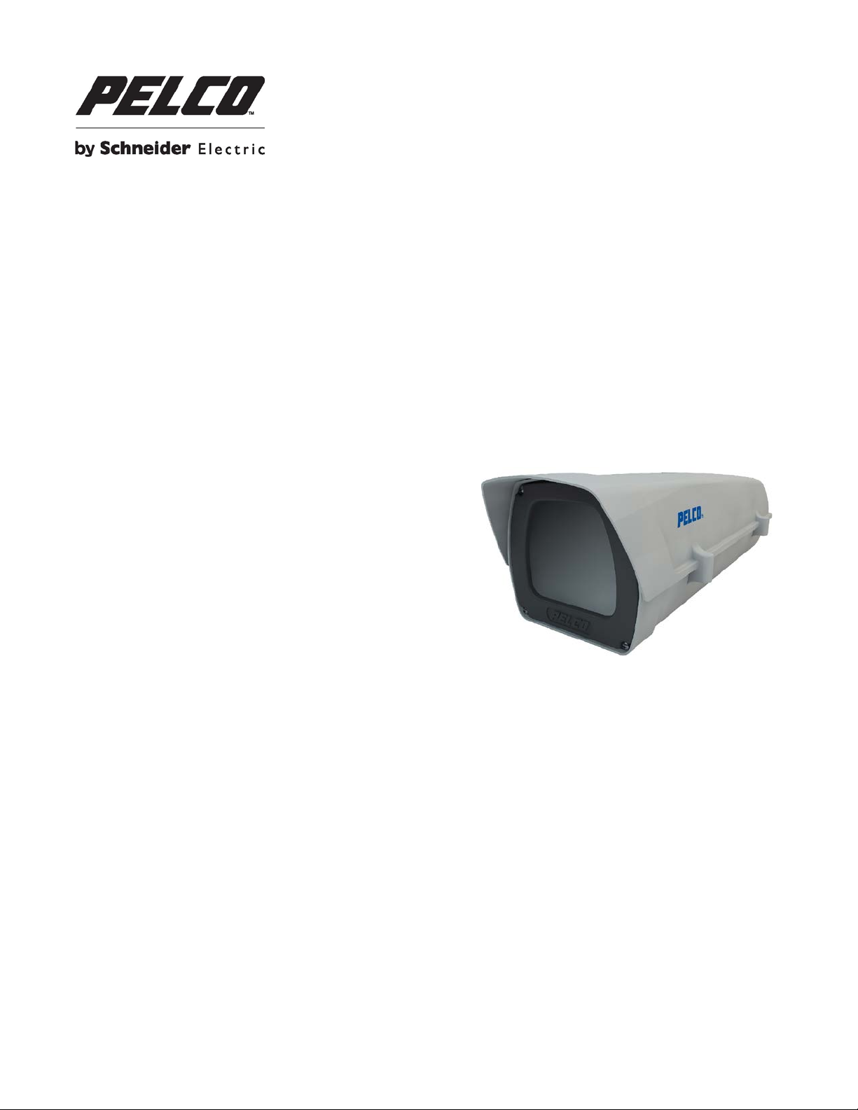
EH14 Series
Enclosure
Installation Manual
C3487M-B (8/14)
1
Page 2

Contents
Important Safety Instructions ........................................................................................................................................................ 3
Warranty ....................................................................................................................................................................................... 3
Description ................................................................................................................................................................................... 4
Specifications ............................................................................................................................................................................... 5
Camera Installation ...................................................................................................................................................................... 6
Pelco Troubleshooting Contact Information ................................................................................................................................. 8
Bracket Installation (Optional) ...................................................................................................................................................... 9
Dimension Drawing ...................................................................................................................................................................... 9
2
Page 3

Important Safety Instructions
This symbol indicates that there are important operating and maintenance instructions in the literature
1. Read these instructions .
2. Keep these instructions.
3. Heed all warnings.
4. Follow all instructions.
5. Only use attachments/accesso r ies specif ied by the manufa ct ur er.
6. Installation should be done only by qualified personnel and conform to all local codes.
7. Use only installation methods and mater ial s capa ble of supp orting four tim es the maximum specified load.
8. Use stainless steel hardware to fasten the mount to outdoor surfaces.
9. To prevent damage from water leakage when installing a mount outdoors on a roof or wall, apply sealant around the bolt
holes between the mount and mounting surface.
CAUTION: These servicing instructions are for use by qualified service personnel only. To reduce the risk of electr ic shoc k do
not perform any servicing other that contained in the operating instructions unless you are qualified to do so.
Only use replacement parts recommended by Pelco.
After replacement/repair of this unit’s electrical components, conduct a resistance measurement between the line and exposed
parts to verify the exposed parts have not been connected to the line circuitry.
The product and/or manual may bear the following marks:
This symbol indicates that dangerous voltage constituting a risk of electric shock is present within this unit.
CAUTION: RISK OF ELECTRIC SHOCK. DO NOT OPEN.
accompanying this unit
Warranty
For information about Pelco’s product warranty and thereto related information, refer to www.pelco.com/warranty.
3
Page 4

Description
The EH14 Series are indoor/outdoor light-duty camera enclosures designed for use with various Pelco and third-party
cameras. The enclosure is constructed of anti-UV and flame resistant polycarbonate plastic.
The lid of the enclosure is hinged to the side providing easy access during installation and when camera and lens adjustments
are necessary. All wiring and cabling is brought into the enclosure through adjustable glands at the lower-rear of the
enclosure.
Some models provide 24VAC for camera power.
MODELS
EH14 Enclosure: indoor/outdoor, glass window, 400 mm (15.75 inch) lower body length with 100 x 86 x 353 mm
(3.94 x 3.39 x 13.90 inch) of internal space for payload, temp range of –40° to +60°C (–40° to 140°F).
EH14-2 Enclosure: same as EH14 except unit is supplied with 24VAC camera power, 24VAC heater and defroster, 30W, and
temp range of –40° to +60°C (–40° to 140°F).
EH14-3 Enclosure: same as EH14 except the window material is optical grade Lexan
camera power, 230VAC heater and defroster, 25W, and temp range of –40° to +60°C (–40° to 140°F).
TM
and the unit is supplied with 24VAC
4
Page 5

Specifications
Operating
Condition
Constant
Temperature
Temperature: -40° to +60°C
Humidity: 0~95%
Temperature: -40° to +60°C
Humidity: 0~95%
Temperature: -40° to +60°C
Humidity: 0~95%
Temperature
Temperature
Model EH14 EH14-2 EH14-3
Indoor / Outdoor
N/A With blower / heater With blower / heater
Input Voltage
12/24 V1 24 VAC1
Output Port N/A
Power N/A
Operational
Range
Controller
Operating
(-40° to 140°F)
N/A
24 VAC camera power
output port
2
30 W
(-40° to 140°F)
25 W2
Heater: 5°C ON
1°C OFF
24 VAC camera power
230 VAC
output port ( ≤8W)
(-40° to 140°F)
Heater: 5°C ON
1°C OFF
Weight 1 KG 1.1 KG 1.35 KG
Window
Material
Body
Material
Glass Glass Optical grade Lexan
Anti-UV flame retardant polycarbonate plastics
IP Grade IP66
TM
Accessory
Note 1: It is intended to be powered from a separate certified limited power source (LPS) power supply not
to exceed 100VA.
Note 2: Does include camera power.
5
1/4-20UNC Screw (1PC) Spring Washer (1PC)
PG11
Cable Glands (2PCS) T25 Torx Wrench (1PC) Cable Tie
Page 6

Camera Installation
Torx T25 wrench
Spring Washer
1/4-20UNC Screw
Use the Torx T25 wrench to remove the two screws on the side of the housing to open the upper cover.
Remove the camera plate. Install the camera on the plate and tighten screw.
The camera position can be adjusted.
6
Page 7

PG11 Cable Glands
Connect with the power supply according to the diagrams bel ow:
7
Page 8

Close the housing and tighten screw.
Pelco Troubleshooting Contact Information
If the instructions provided fail to solve your problem, contact Pelco Product Support at 1-800-289-9100 (USA and Canada) or
+1-559-292-1981 (international) for assistance. Be sure to have the serial number available when calling.
Do not try to repair the unit yourself. Leave maintenance and repairs to qualified technical personnel only.
8
Page 9

Bracket Installation (Optional)
This equipment contains electronic components that must be recycled properly to comply with Directive 2002/96/EC of the European U nio n
©Copyright 2014, Pelco, Inc.
EM14
EM14 PA101 pole mount adapter
EM1009 EM1015U EM1900U
Dimension Drawing
NOTE: VALUES IN PARENTHESES ARE INCHES; ALL OTHERS ARE MILLIMETERS.
regarding the disposal of waste electrical and electronic equipment (WEEE). Contact your local dealer for procedures for recycling this equipment.
Pelco, the Pelco logo, and other trademarks associated with Pelco products referred to in this publication are trademarks of Pelco, Inc. or its affiliates.
ONVIF and the ONVIF logo are trademarks of ONVIF Inc. All other product names and services are the property of their respective companies.
9
All rights reserved.
Page 10

10
 Loading...