

Page 1
OPERATION MANUAL
DX9100VS
®
Viewstation
C639M-A (6/04)
Page 2

2 C639M-A (6/04)
Page 3

CONTENTS
Section Page
IMPORTANT SAFETY INSTRUCTIONS . . . . . . . . . . . . . . . . . . . . . . . . . . . . . . . . . . . . . . . . . . . . . . . . . . . . . . . . . . . . . . . . . . . . . . . . . . . . . . . . . . . . . . . . 6
DESCRIPTION . . . . . . . . . . . . . . . . . . . . . . . . . . . . . . . . . . . . . . . . . . . . . . . . . . . . . . . . . . . . . . . . . . . . . . . . . . . . . . . . . . . . . . . . . . . . . . . . . . . . . . . . . . . 7
GETTING STARTED . . . . . . . . . . . . . . . . . . . . . . . . . . . . . . . . . . . . . . . . . . . . . . . . . . . . . . . . . . . . . . . . . . . . . . . . . . . . . . . . . . . . . . . . . . . . . . . . . . . . . . . 8
VIEWING LIVE VIDE0 . . . . . . . . . . . . . . . . . . . . . . . . . . . . . . . . . . . . . . . . . . . . . . . . . . . . . . . . . . . . . . . . . . . . . . . . . . . . . . . . . . . . . . . . . . . . . . . . . . . . 10
VIEWING RECORDED VIDEO . . . . . . . . . . . . . . . . . . . . . . . . . . . . . . . . . . . . . . . . . . . . . . . . . . . . . . . . . . . . . . . . . . . . . . . . . . . . . . . . . . . . . . . . . . . . . . 12
VIEWING EVENTS . . . . . . . . . . . . . . . . . . . . . . . . . . . . . . . . . . . . . . . . . . . . . . . . . . . . . . . . . . . . . . . . . . . . . . . . . . . . . . . . . . . . . . . . . . . . . . . . . . . . . . 14
USING THE TIME SLIDER . . . . . . . . . . . . . . . . . . . . . . . . . . . . . . . . . . . . . . . . . . . . . . . . . . . . . . . . . . . . . . . . . . . . . . . . . . . . . . . . . . . . . . . . . . . . 14
PERFORMING A QUERY . . . . . . . . . . . . . . . . . . . . . . . . . . . . . . . . . . . . . . . . . . . . . . . . . . . . . . . . . . . . . . . . . . . . . . . . . . . . . . . . . . . . . . . . . . . . . 15
SELECTED TIME RANGE . . . . . . . . . . . . . . . . . . . . . . . . . . . . . . . . . . . . . . . . . . . . . . . . . . . . . . . . . . . . . . . . . . . . . . . . . . . . . . . . . . . . . . . . . 16
SELECTED EVENTS . . . . . . . . . . . . . . . . . . . . . . . . . . . . . . . . . . . . . . . . . . . . . . . . . . . . . . . . . . . . . . . . . . . . . . . . . . . . . . . . . . . . . . . . . . . . . 17
SELECTED CAMERAS . . . . . . . . . . . . . . . . . . . . . . . . . . . . . . . . . . . . . . . . . . . . . . . . . . . . . . . . . . . . . . . . . . . . . . . . . . . . . . . . . . . . . . . . . . . 17
EVENT DATA . . . . . . . . . . . . . . . . . . . . . . . . . . . . . . . . . . . . . . . . . . . . . . . . . . . . . . . . . . . . . . . . . . . . . . . . . . . . . . . . . . . . . . . . . . . . . . . . . . 17
RUNNING THE QUERY . . . . . . . . . . . . . . . . . . . . . . . . . . . . . . . . . . . . . . . . . . . . . . . . . . . . . . . . . . . . . . . . . . . . . . . . . . . . . . . . . . . . . . . . . . 18
CHOOSING FROM THE LATEST EVENTS. . . . . . . . . . . . . . . . . . . . . . . . . . . . . . . . . . . . . . . . . . . . . . . . . . . . . . . . . . . . . . . . . . . . . . . . . . . . . . . . . 18
MARKING EVENTS . . . . . . . . . . . . . . . . . . . . . . . . . . . . . . . . . . . . . . . . . . . . . . . . . . . . . . . . . . . . . . . . . . . . . . . . . . . . . . . . . . . . . . . . . . . . . . . . . . . . . . 19
SEARCHING FOR MOTION DETECTION . . . . . . . . . . . . . . . . . . . . . . . . . . . . . . . . . . . . . . . . . . . . . . . . . . . . . . . . . . . . . . . . . . . . . . . . . . . . . . . . . . . . . . 20
LOCKING/UNLOCKING VIDEO . . . . . . . . . . . . . . . . . . . . . . . . . . . . . . . . . . . . . . . . . . . . . . . . . . . . . . . . . . . . . . . . . . . . . . . . . . . . . . . . . . . . . . . . . . . . . 22
EXPORTING VIDEO . . . . . . . . . . . . . . . . . . . . . . . . . . . . . . . . . . . . . . . . . . . . . . . . . . . . . . . . . . . . . . . . . . . . . . . . . . . . . . . . . . . . . . . . . . . . . . . . . . . . . . 24
EXPORTING A CURRENT FRAME . . . . . . . . . . . . . . . . . . . . . . . . . . . . . . . . . . . . . . . . . . . . . . . . . . . . . . . . . . . . . . . . . . . . . . . . . . . . . . . . . . . . . . . . . . . 25
CAMERA RECORDING PROPERTIES . . . . . . . . . . . . . . . . . . . . . . . . . . . . . . . . . . . . . . . . . . . . . . . . . . . . . . . . . . . . . . . . . . . . . . . . . . . . . . . . . . . . . . . . . 26
CONTINUOUS RECORDING SCHEDULE . . . . . . . . . . . . . . . . . . . . . . . . . . . . . . . . . . . . . . . . . . . . . . . . . . . . . . . . . . . . . . . . . . . . . . . . . . . . . . . . . 28
DAILY RECORDING SCHEDULE . . . . . . . . . . . . . . . . . . . . . . . . . . . . . . . . . . . . . . . . . . . . . . . . . . . . . . . . . . . . . . . . . . . . . . . . . . . . . . . . . . . . . . . . 28
WEEKLY RECORDING SCHEDULE . . . . . . . . . . . . . . . . . . . . . . . . . . . . . . . . . . . . . . . . . . . . . . . . . . . . . . . . . . . . . . . . . . . . . . . . . . . . . . . . . . . . . . 30
MOTION DETECTION . . . . . . . . . . . . . . . . . . . . . . . . . . . . . . . . . . . . . . . . . . . . . . . . . . . . . . . . . . . . . . . . . . . . . . . . . . . . . . . . . . . . . . . . . . . . . . . . 31
CHANNEL SETUP . . . . . . . . . . . . . . . . . . . . . . . . . . . . . . . . . . . . . . . . . . . . . . . . . . . . . . . . . . . . . . . . . . . . . . . . . . . . . . . . . . . . . . . . . . . . . . . . . . . 32
DEFINING USERS . . . . . . . . . . . . . . . . . . . . . . . . . . . . . . . . . . . . . . . . . . . . . . . . . . . . . . . . . . . . . . . . . . . . . . . . . . . . . . . . . . . . . . . . . . . . . . . . . . . . . . . 34
ADVANCED FEATURES . . . . . . . . . . . . . . . . . . . . . . . . . . . . . . . . . . . . . . . . . . . . . . . . . . . . . . . . . . . . . . . . . . . . . . . . . . . . . . . . . . . . . . . . . . . . . . . . . . . 36
AUDIT VIEWER . . . . . . . . . . . . . . . . . . . . . . . . . . . . . . . . . . . . . . . . . . . . . . . . . . . . . . . . . . . . . . . . . . . . . . . . . . . . . . . . . . . . . . . . . . . . . . . . . . . . 36
CREATING REPORTS. . . . . . . . . . . . . . . . . . . . . . . . . . . . . . . . . . . . . . . . . . . . . . . . . . . . . . . . . . . . . . . . . . . . . . . . . . . . . . . . . . . . . . . . . . . . 38
EXPORT VIEWER . . . . . . . . . . . . . . . . . . . . . . . . . . . . . . . . . . . . . . . . . . . . . . . . . . . . . . . . . . . . . . . . . . . . . . . . . . . . . . . . . . . . . . . . . . . . . . . . . . . 42
VIDEO VERIFIER . . . . . . . . . . . . . . . . . . . . . . . . . . . . . . . . . . . . . . . . . . . . . . . . . . . . . . . . . . . . . . . . . . . . . . . . . . . . . . . . . . . . . . . . . . . . . . . . . . . . 44
MAKING A CD OR DVD . . . . . . . . . . . . . . . . . . . . . . . . . . . . . . . . . . . . . . . . . . . . . . . . . . . . . . . . . . . . . . . . . . . . . . . . . . . . . . . . . . . . . . . . . . . . . . 48
SERVER STATE . . . . . . . . . . . . . . . . . . . . . . . . . . . . . . . . . . . . . . . . . . . . . . . . . . . . . . . . . . . . . . . . . . . . . . . . . . . . . . . . . . . . . . . . . . . . . . . . . . . . . 53
ONLINE STORAGE METER . . . . . . . . . . . . . . . . . . . . . . . . . . . . . . . . . . . . . . . . . . . . . . . . . . . . . . . . . . . . . . . . . . . . . . . . . . . . . . . . . . . . . . . . . . . 55
WARRANTY AND RETURN INFORMATION . . . . . . . . . . . . . . . . . . . . . . . . . . . . . . . . . . . . . . . . . . . . . . . . . . . . . . . . . . . . . . . . . . . . . . . . . . . . . . . . . . . 57
C639M-A (6/04) 3
Page 4

LIST OF ILLUSTRATIONS
Figure Page
1. Log-In Dialog Box . . . . . . . . . . . . . . . . . . . . . . . . . . . . . . . . . . . . . . . . . . . . . . . . . . . . . . . . . . . . . . . . . . . . . . . . . . . . . . . . . . . . . . . . . . . . . . . 8
2. DX9100 Main Window . . . . . . . . . . . . . . . . . . . . . . . . . . . . . . . . . . . . . . . . . . . . . . . . . . . . . . . . . . . . . . . . . . . . . . . . . . . . . . . . . . . . . . . . . . . 9
3. Live Video Cameras Section . . . . . . . . . . . . . . . . . . . . . . . . . . . . . . . . . . . . . . . . . . . . . . . . . . . . . . . . . . . . . . . . . . . . . . . . . . . . . . . . . . . . . . 10
4. Video Window . . . . . . . . . . . . . . . . . . . . . . . . . . . . . . . . . . . . . . . . . . . . . . . . . . . . . . . . . . . . . . . . . . . . . . . . . . . . . . . . . . . . . . . . . . . . . . . . 11
5. Recorded Video Cameras Section . . . . . . . . . . . . . . . . . . . . . . . . . . . . . . . . . . . . . . . . . . . . . . . . . . . . . . . . . . . . . . . . . . . . . . . . . . . . . . . . . 12
6. Load Video Dialog Box . . . . . . . . . . . . . . . . . . . . . . . . . . . . . . . . . . . . . . . . . . . . . . . . . . . . . . . . . . . . . . . . . . . . . . . . . . . . . . . . . . . . . . . . . . 12
7. Video Window . . . . . . . . . . . . . . . . . . . . . . . . . . . . . . . . . . . . . . . . . . . . . . . . . . . . . . . . . . . . . . . . . . . . . . . . . . . . . . . . . . . . . . . . . . . . . . . . 13
8. Events Section . . . . . . . . . . . . . . . . . . . . . . . . . . . . . . . . . . . . . . . . . . . . . . . . . . . . . . . . . . . . . . . . . . . . . . . . . . . . . . . . . . . . . . . . . . . . . . . . 15
9. Main Query Window . . . . . . . . . . . . . . . . . . . . . . . . . . . . . . . . . . . . . . . . . . . . . . . . . . . . . . . . . . . . . . . . . . . . . . . . . . . . . . . . . . . . . . . . . . . 15
10. Quick Time Range . . . . . . . . . . . . . . . . . . . . . . . . . . . . . . . . . . . . . . . . . . . . . . . . . . . . . . . . . . . . . . . . . . . . . . . . . . . . . . . . . . . . . . . . . . . . . . 16
11. Continuous Time Range . . . . . . . . . . . . . . . . . . . . . . . . . . . . . . . . . . . . . . . . . . . . . . . . . . . . . . . . . . . . . . . . . . . . . . . . . . . . . . . . . . . . . . . . . 16
12. Daily Time Range . . . . . . . . . . . . . . . . . . . . . . . . . . . . . . . . . . . . . . . . . . . . . . . . . . . . . . . . . . . . . . . . . . . . . . . . . . . . . . . . . . . . . . . . . . . . . . 16
13. Events Query . . . . . . . . . . . . . . . . . . . . . . . . . . . . . . . . . . . . . . . . . . . . . . . . . . . . . . . . . . . . . . . . . . . . . . . . . . . . . . . . . . . . . . . . . . . . . . . . . . 17
14. Cameras Query . . . . . . . . . . . . . . . . . . . . . . . . . . . . . . . . . . . . . . . . . . . . . . . . . . . . . . . . . . . . . . . . . . . . . . . . . . . . . . . . . . . . . . . . . . . . . . . . 17
15. Event Data . . . . . . . . . . . . . . . . . . . . . . . . . . . . . . . . . . . . . . . . . . . . . . . . . . . . . . . . . . . . . . . . . . . . . . . . . . . . . . . . . . . . . . . . . . . . . . . . . . . 17
16. Preview Window . . . . . . . . . . . . . . . . . . . . . . . . . . . . . . . . . . . . . . . . . . . . . . . . . . . . . . . . . . . . . . . . . . . . . . . . . . . . . . . . . . . . . . . . . . . . . . 18
17. Events Section . . . . . . . . . . . . . . . . . . . . . . . . . . . . . . . . . . . . . . . . . . . . . . . . . . . . . . . . . . . . . . . . . . . . . . . . . . . . . . . . . . . . . . . . . . . . . . . . 18
18. Large Screen . . . . . . . . . . . . . . . . . . . . . . . . . . . . . . . . . . . . . . . . . . . . . . . . . . . . . . . . . . . . . . . . . . . . . . . . . . . . . . . . . . . . . . . . . . . . . . . . . . 19
19. Mark Event Dialog Box . . . . . . . . . . . . . . . . . . . . . . . . . . . . . . . . . . . . . . . . . . . . . . . . . . . . . . . . . . . . . . . . . . . . . . . . . . . . . . . . . . . . . . . . . . 19
20. Sherlock Section . . . . . . . . . . . . . . . . . . . . . . . . . . . . . . . . . . . . . . . . . . . . . . . . . . . . . . . . . . . . . . . . . . . . . . . . . . . . . . . . . . . . . . . . . . . . . . . 20
21. Marking An Object . . . . . . . . . . . . . . . . . . . . . . . . . . . . . . . . . . . . . . . . . . . . . . . . . . . . . . . . . . . . . . . . . . . . . . . . . . . . . . . . . . . . . . . . . . . . . 20
22. Scan In Progress Message . . . . . . . . . . . . . . . . . . . . . . . . . . . . . . . . . . . . . . . . . . . . . . . . . . . . . . . . . . . . . . . . . . . . . . . . . . . . . . . . . . . . . . . 21
23. Event Found Dialog Box . . . . . . . . . . . . . . . . . . . . . . . . . . . . . . . . . . . . . . . . . . . . . . . . . . . . . . . . . . . . . . . . . . . . . . . . . . . . . . . . . . . . . . . . . 21
24. Window for Locking Video . . . . . . . . . . . . . . . . . . . . . . . . . . . . . . . . . . . . . . . . . . . . . . . . . . . . . . . . . . . . . . . . . . . . . . . . . . . . . . . . . . . . . . . 22
26. Lock Video Message. . . . . . . . . . . . . . . . . . . . . . . . . . . . . . . . . . . . . . . . . . . . . . . . . . . . . . . . . . . . . . . . . . . . . . . . . . . . . . . . . . . . . . . . . . . . 23
25. Dialog Box for Reason to Lock Video . . . . . . . . . . . . . . . . . . . . . . . . . . . . . . . . . . . . . . . . . . . . . . . . . . . . . . . . . . . . . . . . . . . . . . . . . . . . . . . 23
27. Lock Section . . . . . . . . . . . . . . . . . . . . . . . . . . . . . . . . . . . . . . . . . . . . . . . . . . . . . . . . . . . . . . . . . . . . . . . . . . . . . . . . . . . . . . . . . . . . . . . . . . 23
28. Exporting Video Window . . . . . . . . . . . . . . . . . . . . . . . . . . . . . . . . . . . . . . . . . . . . . . . . . . . . . . . . . . . . . . . . . . . . . . . . . . . . . . . . . . . . . . . . 24
29. Time Slider Video Section . . . . . . . . . . . . . . . . . . . . . . . . . . . . . . . . . . . . . . . . . . . . . . . . . . . . . . . . . . . . . . . . . . . . . . . . . . . . . . . . . . . . . . . 24
30. Exporting Current Frame Window . . . . . . . . . . . . . . . . . . . . . . . . . . . . . . . . . . . . . . . . . . . . . . . . . . . . . . . . . . . . . . . . . . . . . . . . . . . . . . . . . 25
31. Camera Properties Dialog Box . . . . . . . . . . . . . . . . . . . . . . . . . . . . . . . . . . . . . . . . . . . . . . . . . . . . . . . . . . . . . . . . . . . . . . . . . . . . . . . . . . . . 26
32. Select Channel Dialog Box . . . . . . . . . . . . . . . . . . . . . . . . . . . . . . . . . . . . . . . . . . . . . . . . . . . . . . . . . . . . . . . . . . . . . . . . . . . . . . . . . . . . . . . 27
33. Continuous Recording Schedule Page . . . . . . . . . . . . . . . . . . . . . . . . . . . . . . . . . . . . . . . . . . . . . . . . . . . . . . . . . . . . . . . . . . . . . . . . . . . . . . 27
34. Continuous Daily Recording Schedule Page . . . . . . . . . . . . . . . . . . . . . . . . . . . . . . . . . . . . . . . . . . . . . . . . . . . . . . . . . . . . . . . . . . . . . . . . . 28
35. Daily Event Recording Page . . . . . . . . . . . . . . . . . . . . . . . . . . . . . . . . . . . . . . . . . . . . . . . . . . . . . . . . . . . . . . . . . . . . . . . . . . . . . . . . . . . . . . 29
37. Weekly Event Recording Schedule Page . . . . . . . . . . . . . . . . . . . . . . . . . . . . . . . . . . . . . . . . . . . . . . . . . . . . . . . . . . . . . . . . . . . . . . . . . . . . 30
36. Continuous Weekly Recording Schedule Page . . . . . . . . . . . . . . . . . . . . . . . . . . . . . . . . . . . . . . . . . . . . . . . . . . . . . . . . . . . . . . . . . . . . . . . 30
38. Motion Detection Page . . . . . . . . . . . . . . . . . . . . . . . . . . . . . . . . . . . . . . . . . . . . . . . . . . . . . . . . . . . . . . . . . . . . . . . . . . . . . . . . . . . . . . . . . 31
39. Camera Video Setup Page . . . . . . . . . . . . . . . . . . . . . . . . . . . . . . . . . . . . . . . . . . . . . . . . . . . . . . . . . . . . . . . . . . . . . . . . . . . . . . . . . . . . . . . 32
40. User Access Message Box . . . . . . . . . . . . . . . . . . . . . . . . . . . . . . . . . . . . . . . . . . . . . . . . . . . . . . . . . . . . . . . . . . . . . . . . . . . . . . . . . . . . . . . 34
41. User Manager Dialog Box . . . . . . . . . . . . . . . . . . . . . . . . . . . . . . . . . . . . . . . . . . . . . . . . . . . . . . . . . . . . . . . . . . . . . . . . . . . . . . . . . . . . . . . 34
42. Audit Viewer Login Dialog Box. . . . . . . . . . . . . . . . . . . . . . . . . . . . . . . . . . . . . . . . . . . . . . . . . . . . . . . . . . . . . . . . . . . . . . . . . . . . . . . . . . . . 36
43. Audit Viewer Window . . . . . . . . . . . . . . . . . . . . . . . . . . . . . . . . . . . . . . . . . . . . . . . . . . . . . . . . . . . . . . . . . . . . . . . . . . . . . . . . . . . . . . . . . . 36
44. Modify Columns Page . . . . . . . . . . . . . . . . . . . . . . . . . . . . . . . . . . . . . . . . . . . . . . . . . . . . . . . . . . . . . . . . . . . . . . . . . . . . . . . . . . . . . . . . . . 38
45. Filter Page . . . . . . . . . . . . . . . . . . . . . . . . . . . . . . . . . . . . . . . . . . . . . . . . . . . . . . . . . . . . . . . . . . . . . . . . . . . . . . . . . . . . . . . . . . . . . . . . . . . . 38
46. Select Category Dialog Box . . . . . . . . . . . . . . . . . . . . . . . . . . . . . . . . . . . . . . . . . . . . . . . . . . . . . . . . . . . . . . . . . . . . . . . . . . . . . . . . . . . . . . 39
47. Select Users Dialog Box . . . . . . . . . . . . . . . . . . . . . . . . . . . . . . . . . . . . . . . . . . . . . . . . . . . . . . . . . . . . . . . . . . . . . . . . . . . . . . . . . . . . . . . . . 39
48. Select Servers Dialog Box . . . . . . . . . . . . . . . . . . . . . . . . . . . . . . . . . . . . . . . . . . . . . . . . . . . . . . . . . . . . . . . . . . . . . . . . . . . . . . . . . . . . . . . 40
49. Select Date & Time Dialog Box . . . . . . . . . . . . . . . . . . . . . . . . . . . . . . . . . . . . . . . . . . . . . . . . . . . . . . . . . . . . . . . . . . . . . . . . . . . . . . . . . . . 40
50. Select Viewstations Dialog Box . . . . . . . . . . . . . . . . . . . . . . . . . . . . . . . . . . . . . . . . . . . . . . . . . . . . . . . . . . . . . . . . . . . . . . . . . . . . . . . . . . . 40
51. Order Page . . . . . . . . . . . . . . . . . . . . . . . . . . . . . . . . . . . . . . . . . . . . . . . . . . . . . . . . . . . . . . . . . . . . . . . . . . . . . . . . . . . . . . . . . . . . . . . . . . . 41
52. Sample Audit Report . . . . . . . . . . . . . . . . . . . . . . . . . . . . . . . . . . . . . . . . . . . . . . . . . . . . . . . . . . . . . . . . . . . . . . . . . . . . . . . . . . . . . . . . . . . 41
53. Export Viewer Window. . . . . . . . . . . . . . . . . . . . . . . . . . . . . . . . . . . . . . . . . . . . . . . . . . . . . . . . . . . . . . . . . . . . . . . . . . . . . . . . . . . . . . . . . . 42
54. Open Video File Dialog Box . . . . . . . . . . . . . . . . . . . . . . . . . . . . . . . . . . . . . . . . . . . . . . . . . . . . . . . . . . . . . . . . . . . . . . . . . . . . . . . . . . . . . . 42
55. Video Playback . . . . . . . . . . . . . . . . . . . . . . . . . . . . . . . . . . . . . . . . . . . . . . . . . . . . . . . . . . . . . . . . . . . . . . . . . . . . . . . . . . . . . . . . . . . . . . . . 43
56. Video Originality Verifier Window . . . . . . . . . . . . . . . . . . . . . . . . . . . . . . . . . . . . . . . . . . . . . . . . . . . . . . . . . . . . . . . . . . . . . . . . . . . . . . . . . 44
57. Open Verifier File Dialog Box . . . . . . . . . . . . . . . . . . . . . . . . . . . . . . . . . . . . . . . . . . . . . . . . . . . . . . . . . . . . . . . . . . . . . . . . . . . . . . . . . . . . . 45
58. Verifier Information Window . . . . . . . . . . . . . . . . . . . . . . . . . . . . . . . . . . . . . . . . . . . . . . . . . . . . . . . . . . . . . . . . . . . . . . . . . . . . . . . . . . . . . 45
4 C639M-A (6/04)
Page 5

59. Failed File Structure Message . . . . . . . . . . . . . . . . . . . . . . . . . . . . . . . . . . . . . . . . . . . . . . . . . . . . . . . . . . . . . . . . . . . . . . . . . . . . . . . . . . . . 46
60. Welcome Window . . . . . . . . . . . . . . . . . . . . . . . . . . . . . . . . . . . . . . . . . . . . . . . . . . . . . . . . . . . . . . . . . . . . . . . . . . . . . . . . . . . . . . . . . . . . . 48
61. Data Window . . . . . . . . . . . . . . . . . . . . . . . . . . . . . . . . . . . . . . . . . . . . . . . . . . . . . . . . . . . . . . . . . . . . . . . . . . . . . . . . . . . . . . . . . . . . . . . . . 48
62. Add Files Window . . . . . . . . . . . . . . . . . . . . . . . . . . . . . . . . . . . . . . . . . . . . . . . . . . . . . . . . . . . . . . . . . . . . . . . . . . . . . . . . . . . . . . . . . . . . . 49
63. Select Files and Folders Window . . . . . . . . . . . . . . . . . . . . . . . . . . . . . . . . . . . . . . . . . . . . . . . . . . . . . . . . . . . . . . . . . . . . . . . . . . . . . . . . . . 49
64. Added File Window . . . . . . . . . . . . . . . . . . . . . . . . . . . . . . . . . . . . . . . . . . . . . . . . . . . . . . . . . . . . . . . . . . . . . . . . . . . . . . . . . . . . . . . . . . . . 50
65. Final Burn Settings Window . . . . . . . . . . . . . . . . . . . . . . . . . . . . . . . . . . . . . . . . . . . . . . . . . . . . . . . . . . . . . . . . . . . . . . . . . . . . . . . . . . . . . 50
66. Data Verification Dialog Box . . . . . . . . . . . . . . . . . . . . . . . . . . . . . . . . . . . . . . . . . . . . . . . . . . . . . . . . . . . . . . . . . . . . . . . . . . . . . . . . . . . . . 51
67. Burning Process Window . . . . . . . . . . . . . . . . . . . . . . . . . . . . . . . . . . . . . . . . . . . . . . . . . . . . . . . . . . . . . . . . . . . . . . . . . . . . . . . . . . . . . . . . 51
68. Exit Window . . . . . . . . . . . . . . . . . . . . . . . . . . . . . . . . . . . . . . . . . . . . . . . . . . . . . . . . . . . . . . . . . . . . . . . . . . . . . . . . . . . . . . . . . . . . . . . . . . 52
70. Configuration Options . . . . . . . . . . . . . . . . . . . . . . . . . . . . . . . . . . . . . . . . . . . . . . . . . . . . . . . . . . . . . . . . . . . . . . . . . . . . . . . . . . . . . . . . . . 53
69. Server State . . . . . . . . . . . . . . . . . . . . . . . . . . . . . . . . . . . . . . . . . . . . . . . . . . . . . . . . . . . . . . . . . . . . . . . . . . . . . . . . . . . . . . . . . . . . . . . . . . 53
71. Error Alert Message . . . . . . . . . . . . . . . . . . . . . . . . . . . . . . . . . . . . . . . . . . . . . . . . . . . . . . . . . . . . . . . . . . . . . . . . . . . . . . . . . . . . . . . . . . . . 54
72. Online Storage Meter . . . . . . . . . . . . . . . . . . . . . . . . . . . . . . . . . . . . . . . . . . . . . . . . . . . . . . . . . . . . . . . . . . . . . . . . . . . . . . . . . . . . . . . . . . . 55
73. Storage Consumption Graph . . . . . . . . . . . . . . . . . . . . . . . . . . . . . . . . . . . . . . . . . . . . . . . . . . . . . . . . . . . . . . . . . . . . . . . . . . . . . . . . . . . . . 55
LIST OF TABLES
Table Page
A. Event Types . . . . . . . . . . . . . . . . . . . . . . . . . . . . . . . . . . . . . . . . . . . . . . . . . . . . . . . . . . . . . . . . . . . . . . . . . . . . . . . . . . . . . . . . . . . . . . . . . . . 14
B. Channel Setup . . . . . . . . . . . . . . . . . . . . . . . . . . . . . . . . . . . . . . . . . . . . . . . . . . . . . . . . . . . . . . . . . . . . . . . . . . . . . . . . . . . . . . . . . . . . . . . . 33
C. User Access Rights . . . . . . . . . . . . . . . . . . . . . . . . . . . . . . . . . . . . . . . . . . . . . . . . . . . . . . . . . . . . . . . . . . . . . . . . . . . . . . . . . . . . . . . . . . . . . 35
D. Audit Viewer Toolbar . . . . . . . . . . . . . . . . . . . . . . . . . . . . . . . . . . . . . . . . . . . . . . . . . . . . . . . . . . . . . . . . . . . . . . . . . . . . . . . . . . . . . . . . . . . 37
E. Verifier Information Panel . . . . . . . . . . . . . . . . . . . . . . . . . . . . . . . . . . . . . . . . . . . . . . . . . . . . . . . . . . . . . . . . . . . . . . . . . . . . . . . . . . . . . . . 46
F. Failed Test Information . . . . . . . . . . . . . . . . . . . . . . . . . . . . . . . . . . . . . . . . . . . . . . . . . . . . . . . . . . . . . . . . . . . . . . . . . . . . . . . . . . . . . . . . . . 47
G. Video Verifier Buttons . . . . . . . . . . . . . . . . . . . . . . . . . . . . . . . . . . . . . . . . . . . . . . . . . . . . . . . . . . . . . . . . . . . . . . . . . . . . . . . . . . . . . . . . . . 47
H. Server State Symbols . . . . . . . . . . . . . . . . . . . . . . . . . . . . . . . . . . . . . . . . . . . . . . . . . . . . . . . . . . . . . . . . . . . . . . . . . . . . . . . . . . . . . . . . . . . 54
C639M-A (6/04) 5
Page 6

IMPORTANT SAFETY INSTRUCTIONS
1. Read these instructions.
2. Keep these instructions.
3. Heed all warnings.
4. Follow all instructions.
5. Do not use this apparatus near water.
6. Clean only with dry cloth.
7. Do not block any ventilation openings. Install in accordance with the manufacturer’s instructions.
8. Do not install near any heat sources such as radiators, heat registers, stoves, or other apparatus (including amplifiers)
that produce heat.
9. Do not defeat the safety purpose of the polarized or grounding-type plug. A polarized plug has two blades with one wider
than the other. A grounding plug has two blades and a third grounding prong. The wide blade or the third prong is
provided for your safety. If the provided plug does not fit into your outlet, consult your electrician for replacement of the
obsolete outlet.
10. Protect the power cord from being walked on or pinched, particularly at the plug, convenience receptacle, and the point
where it exits from the apparatus.
11. Only use attachments/accessories specified by the manufacturer.
12. Use only with the cart, stand, tripod, bracket, or table specified by the manufacturer, or sold with the apparatus. When a
cart is used, use caution when using the cart/apparatus combination to avoid injury from tip-over.
13. Refer all servicing to qualified service personnel. Servicing is required when the apparatus has been damaged in any way,
such as when the power supply cord or plug is damaged, liquid has been spilled or objects have fallen into the apparatus,
the apparatus has been exposed to rain or moisture, the apparatus does not operate normally, or the apparatus has been
dropped.
14. Apparatus should not be exposed to dripping or splashing, and no objects filled with liquids, such as vases, should be
placed on the apparatus.
15. WARNING: To reduce the risk of fire or electric shock, do not expose this apparatus to rain or moisture.
16. Installation should be done only by qualified personnel and conform to all local codes.
17. Use only installation methods and materials capable of supporting four times the maximum specified load.
The socket-outlet shall be installed near the equipment and shall be easily accessible.
CAUTION: These servicing instructions are for use by qualified service personnel only. To reduce the risk of electric shock do
not perform any servicing other that contained in the operating instructions unless you are qualified to do so.
CAUTION: Danger of explosion if battery is incorrectly replaced. Replace only with the same or equivalent type. Dispose of
used batteries according to the instructions provided by the battery manufacturer.
Only use replacement parts recommended by Pelco.
6 C639M-A (6/04)
Page 7

DESCRIPTION
This manual provides instructions for operating your DX9100VS viewstation, which is your interface with the DX9000 and
DX9100 digital video recorders. The viewstation offers many functions, including the following:
• Simultaneous viewing of live or recorded video can be seen from as many as four cameras.
• Live video can be marked for later review by the user or via motion detection.
•A scan feature allows the user to search recorded video for movement of a specific object.
•Video files can be saved in MPEG format to a compact disk, hard drive, or anywhere on the network.
•A current video frame can be printed on a standard PC printer.
C639M-A (6/04) 7
Page 8
GETTING STARTED
The viewstation is already connected to the recorder and ready to operate. All you have to do is turn it on, log in, and then drag
and drop cameras into the four windows to begin viewing video.
The recording schedule and who can operate the viewstation should have been set up during the installation process. If you
want to change the recording schedule or change the users who are authorized to use this viewstation, refer to the sections on
Camera Recording Properties
1. Turn the system on.
NOTE: Make sure you turn on the recorder first, and then the viewstation.
The system powers up and logs on automatically to the network. After a few seconds, the DX9100 viewstation dialog box
appears automatically. If the log-in dialog box does not appear, double-click the DX9100 viewstation icon on your desktop.
and
Defining Users.
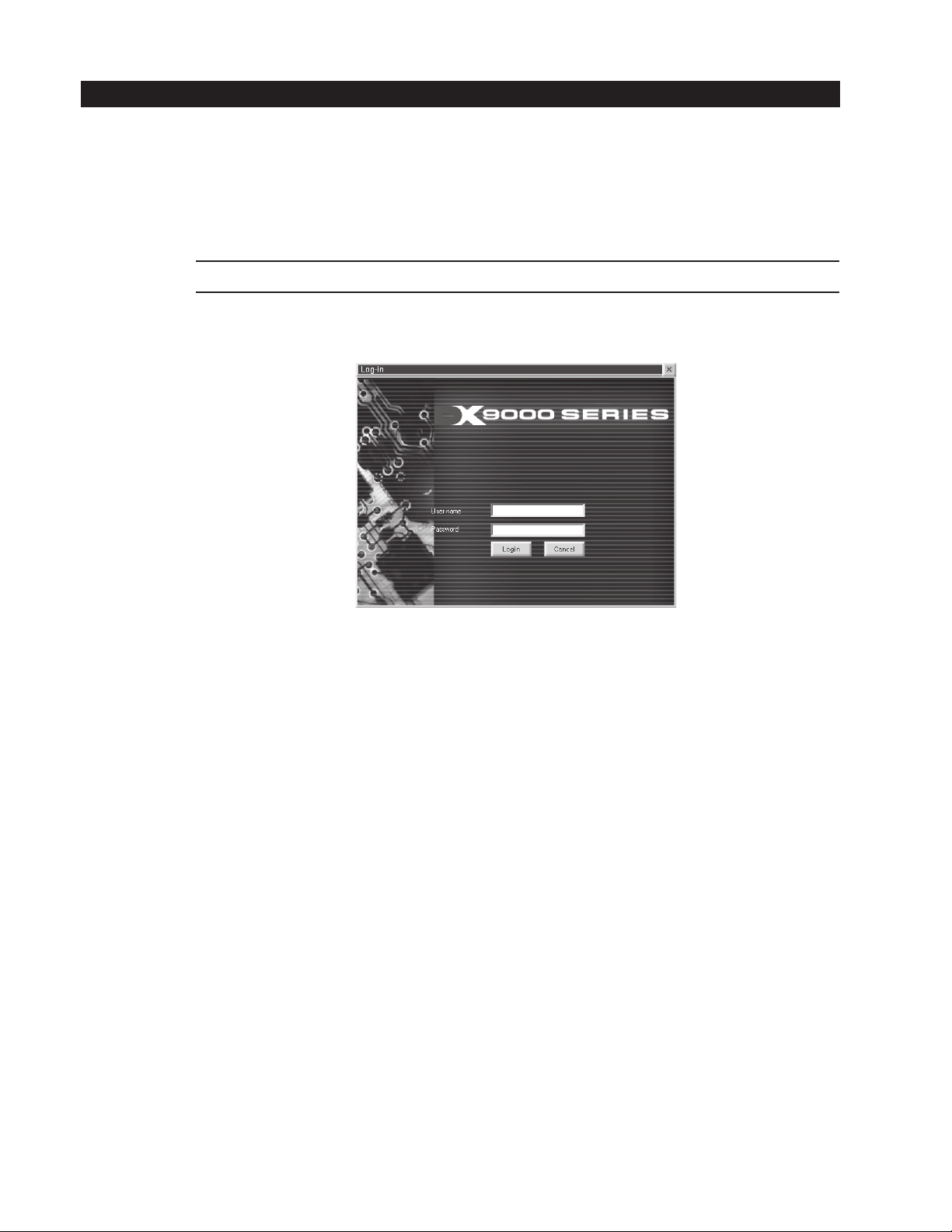
Figure 1. Log-In Dialog Box
2. Enter your “User name” and Password.
3. Click Login. The main window appears. Refer to Figure 2.
8 C639M-A (6/04)
Page 9
Main Toolbar
Cameras Section
Video Windows
Sherlock Section
Date and Time
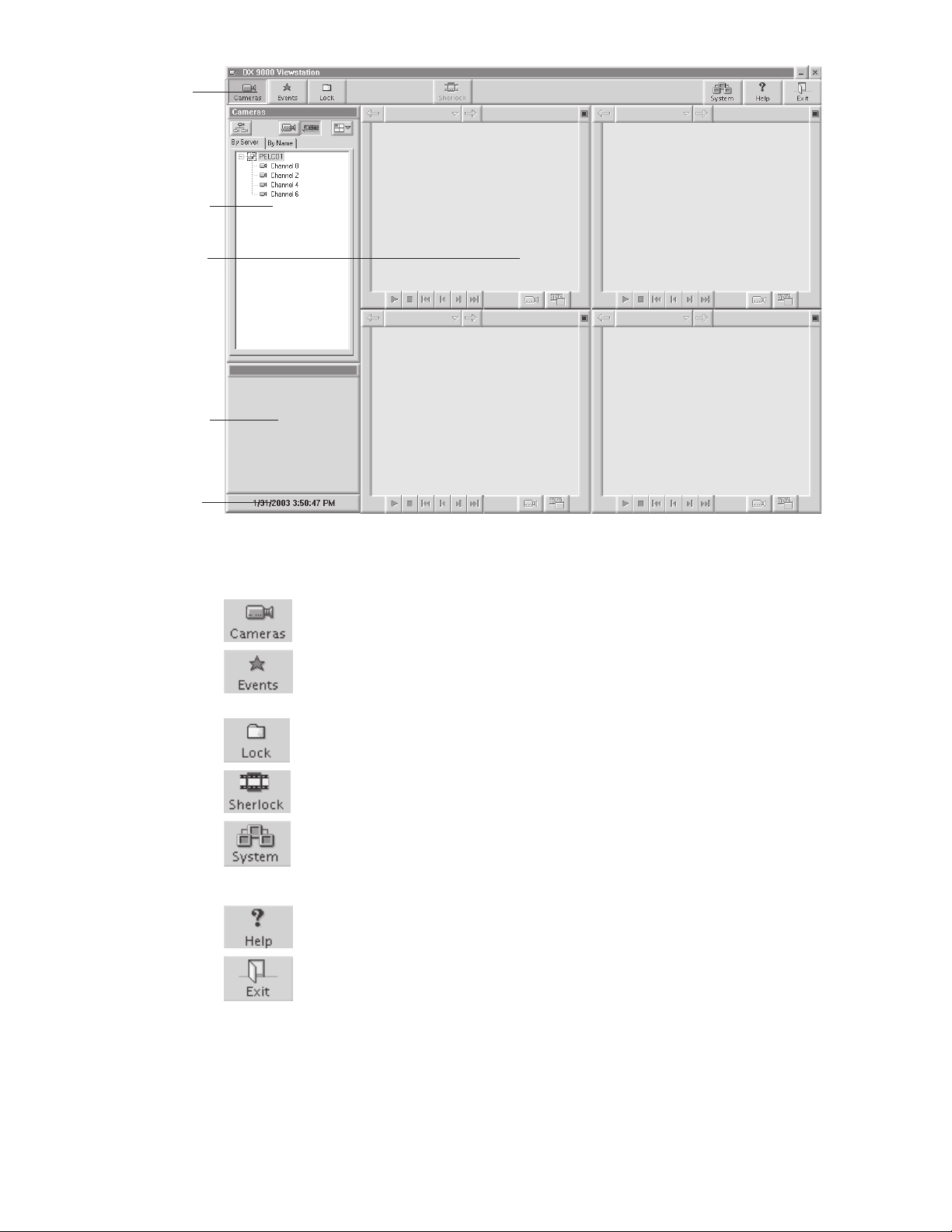
Figure 2. DX9100 Main Window
Main Toolbar: The toolbar consists of seven operation buttons.
Displays the cameras that are defined in the system by server or by name.
Displays the latest events that have occurred in the system by camera or by time. You can define and view new
event queries.
Unlocks locked video files. You can also view videos that have been locked.
Scans recorded video for movement or disappearance of a specific object.
Sets camera properties and defines users. This button is available only to system administrators and operators
with a Level 1 authorization. System administrators and Level 1 operators can set camera properties, but only
system administrators can define users.
Accesses online help.
Exits the application.
Video Windows: Each of the four video windows displays a live or playback video.
Cameras Section: This is the default section. The Events and Lock sections also appear here.
Sherlock Section: This section appears when you click Sherlock. It allows you to search for motion detection, including the
disappearance of objects, during playback video.
Date and Time: The current date and time is displayed.
C639M-A (6/04) 9
Page 10

VIEWING LIVE VIDE0
You can view up to four different live videos on a DX9100 viewstation at the same time.
1. Click .
2. Click to expand the server and show all of the cameras.
Figure 3. Live Video Cameras Section
NOTE: You can right-click a camera to see its properties.
3. Click
4. Drag and drop a camera into one of the windows.
NOTE: You can also click to select a window. It displays four drop-down buttons. Each button has a blue square that
shows the window that will play the video. For example, this button will play the video in the top left window.
5. Click while viewing live video if you want a bigger view.
6. Click
to view live video.
to return to four windows.
10 C639M-A (6/04)
Page 11
Title Bar
Play Bar
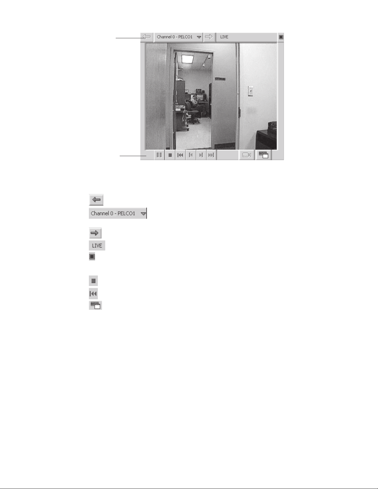
Figure 4. Video Window
Title Bar
Moves to the previous video in memory that was displayed in this window.
Shows the current camera name and site. Displays a drop-down box of the last 10 videos shown.
The most recent video is at the bottom of the list.
Moves to the next video in memory that was displayed in this window.
Appears on the title bar if the video is live.
Switches the video to a larger screen.
Play Bar
Closes the video window.
Rewinds video 1 minute.
Switches to the load video dialog box.
C639M-A (6/04) 11
Page 12
VIEWING RECORDED VIDEO
You can view up to four different playback (recorded) videos on a DX9100 viewstation at the same time.
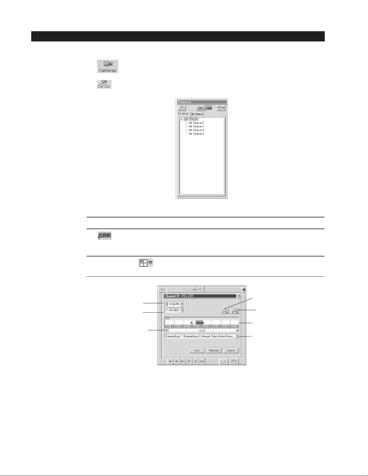
1. Click .
2. Click to expand the server and show all of the cameras.
Figure 5. Recorded Video Cameras Section
NOTE: You can right-click a camera to see its properties.
3. Click
4. Drag and drop a camera into one of the windows.
NOTE: You can also click
that shows the window that will play the video. For example, this button will play the video in the top left window.
Time Box: Displays the time of the playback video.
Date Box: Displays the date of the video. You can enter a new date or select a new date from the drop-down calendar.
Zoom Out: Zooms out on the event bar to a maximum of one week.
Zoom In: Zooms in on the event bar to a minimum of one minute.
Event Bar: Displays events.
Time Slider: Moves the time and date forward or backward.
Event Box: Displays the current event types for the video. You can select or clear events from the drop-down box. All events
to view playback video.
Time Box
Date Box
Time Slider
are selected by default.
to select a window. It displays four drop-down buttons. Each button has a blue square
Zoom Out
Zoom In
Event Bar
Event Box
Figure 6. Load Video Dialog Box
12 C639M-A (6/04)
Page 13
5. Select a date and time.
6. Click Playback.
7. Click
while viewing recorded video if you want a bigger view.
8. Click to return to four windows.
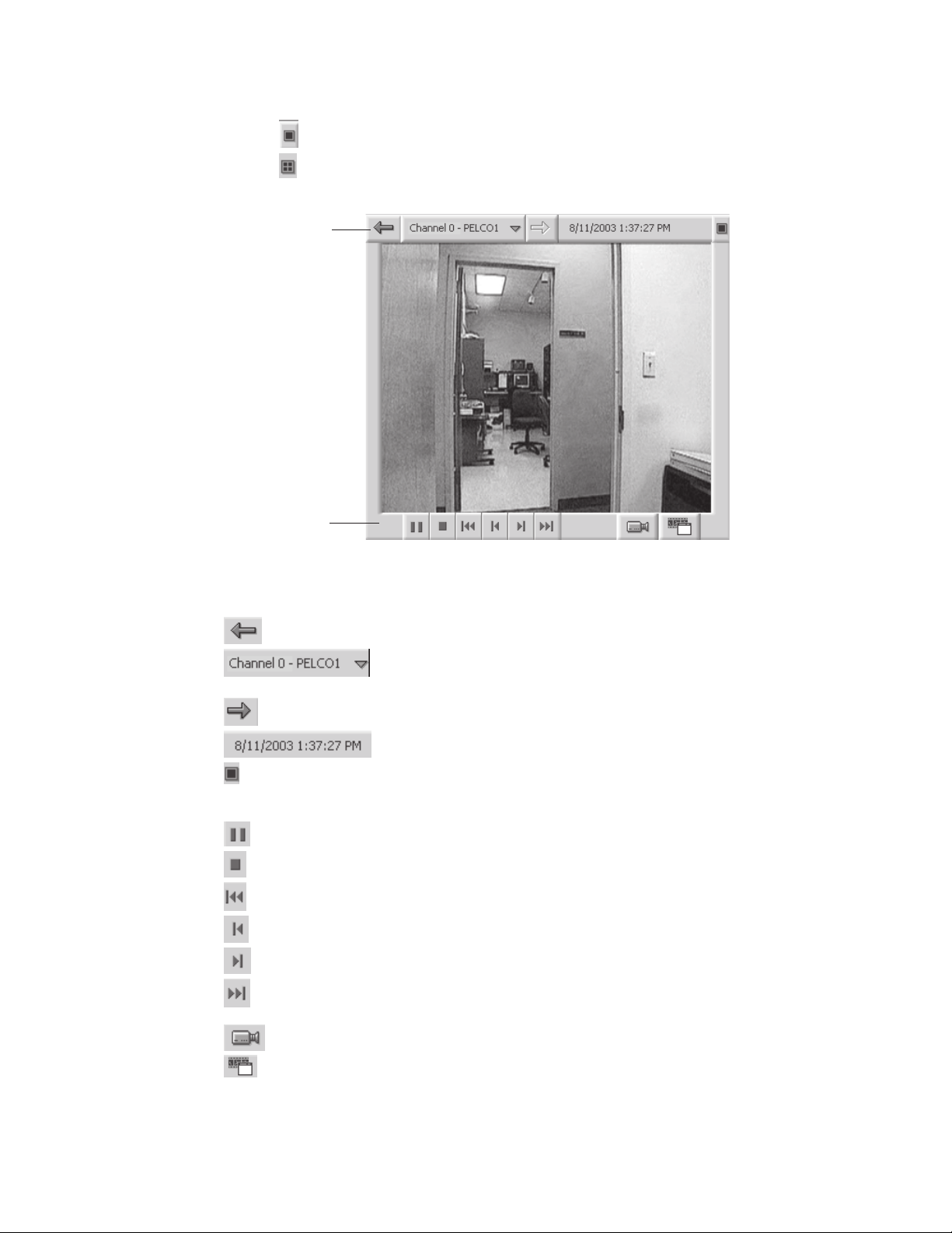
Title Bar
Play Bar
Figure 7. Video Window
Title Bar
Moves to the previous video in memory that was displayed in this window.
Shows the current camera name and site. Displays a drop-down box of the last 10 videos shown.
The most recent video is at the bottom of the list.
Moves to the next video in memory that was displayed in this window.
Displays the date and time on the title bar if the video is recorded.
Switches the video to a larger screen.
Play Bar
Pauses the video. This button is not available when viewing live video.
Closes the video window.
Rewinds video 10 seconds.
Rewinds video one second. This button is not available when viewing live video.
Forwards video one second. This button is not available when viewing live video.
Forwards video 10 seconds. This button is not available when viewing live video.
Switches to live video. This button is not available when viewing live video.
Switches to the load video dialog box.
C639M-A (6/04) 13
Page 14
VIEWING EVENTS
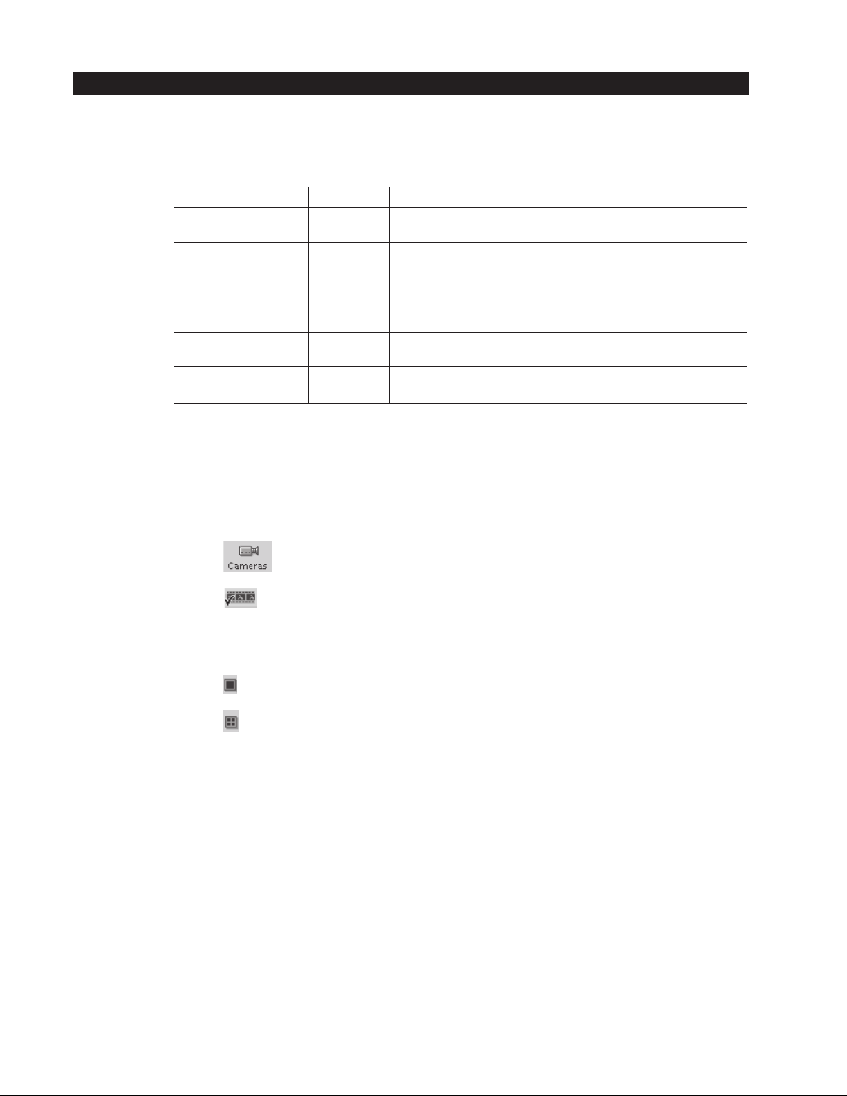
Events are videos of specific occurrences that have been marked for your review. There are six types of events that can be
identified in the DX9100 viewstation. Each event type is assigned a star with a specific color for easy identification on the time
slider.
Event Type Star Color Description
External Input 1 Silver An event imported into the DX9100 system from external devices, such as
External Input 2 Gold An event imported into the DX9100 system from external devices, such as
Manual Black An event marked manually by the user.
Video Motion Detection Red An event marked automatically by the DVMD system when the DVMD
No Signal Detection Blue An event marked automatically when there is no signal from the camera
Signal Detection Light Green An event marked automatically when the signal from the camera is
There are three ways to view events:
• Using the time slider
• Doing a query
• Choosing from the latest events
Table A. Event Types
alarm units or access control systems.
alarm units or access control systems.
recognizes movement in the predefined area(s).
due to a failure. This event appears only once when the camera fails.
reidentified. This event appears only once when the camera is reidentified.
USING THE TIME SLIDER
1. Click .
2. Click to view playback video.
3. Click an event (star) on the time slider. The time box and date box show the time and date of the event.
4. Click Playback.
5. Click
6. Click
while viewing the video if you want a bigger view.
to return to four windows.
14 C639M-A (6/04)
Page 15
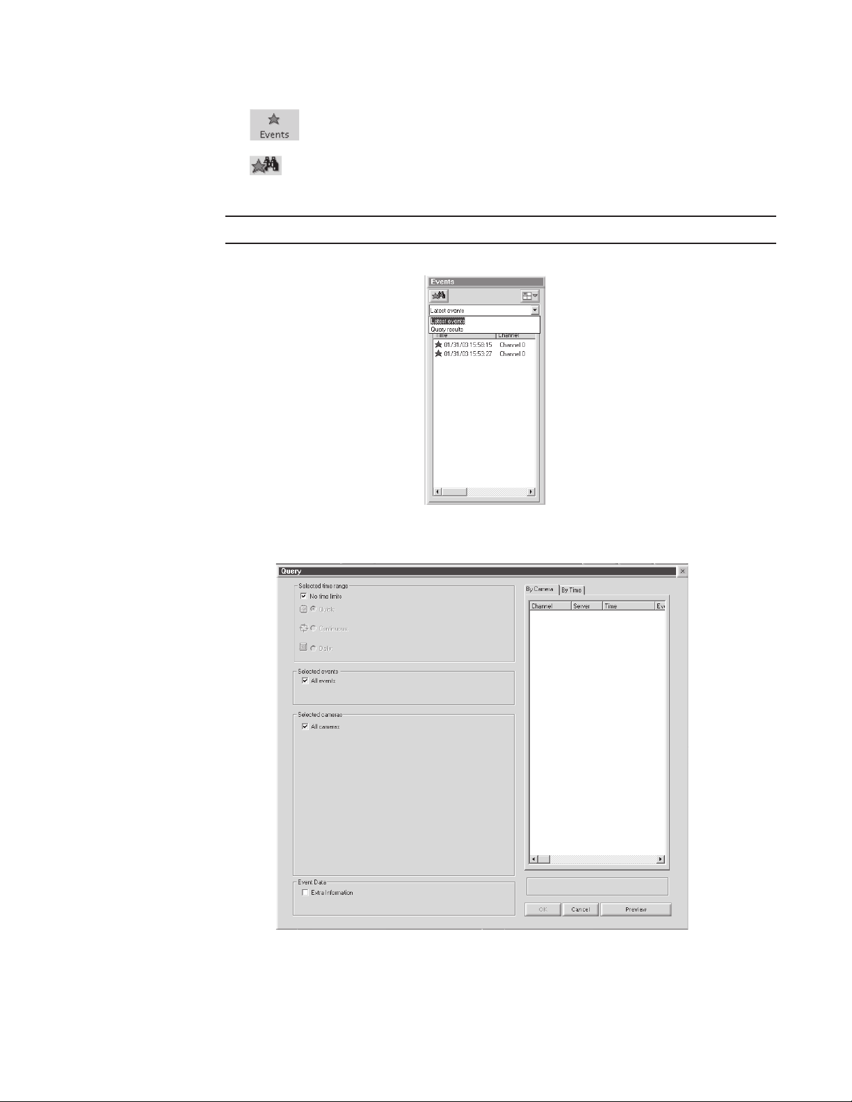
PERFORMING A QUERY
1. Click .
2. Click
3. Select the query parameters.
NOTE: By default, the query includes all events, cameras, and dates and times.
.
Figure 8. Events Section
Figure 9. Main Query Window
C639M-A (6/04) 15
Page 16
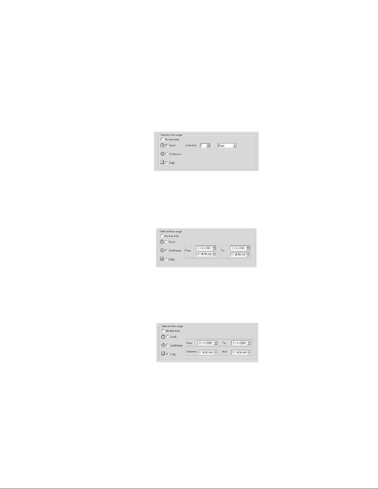
SELECTED TIME RANGE
You can select three different date and time periods:
• Quick: Perform a quick search within the last x hours or x days.
• Continuous: Search for events over a specified period.
• Daily: Search for events every day during the specified dates, between the specified times. For example, search for
events every day in the month of January between 20:00 and 22:00.
Quick
1. Clear the “No time limits” checkbox.
2. Select the Quick radio button.
3. Select the number of days/hours from the “In the last” field.
4. Select days or hours.
Figure 10. Quick Time Range
Continuous
1. Clear the “No time limits” checkbox.
2. Select the Continuous radio button.
3. Select the start date/time and the end date/time. The default is the current date and time.
Figure 11. Continuous Time Range
Daily
1. Clear the “No time limits” checkbox.
2. Select the Daily radio button.
3. Select the start date and end date and the time period.
Figure 12. Daily Time Range
16 C639M-A (6/04)
Page 17
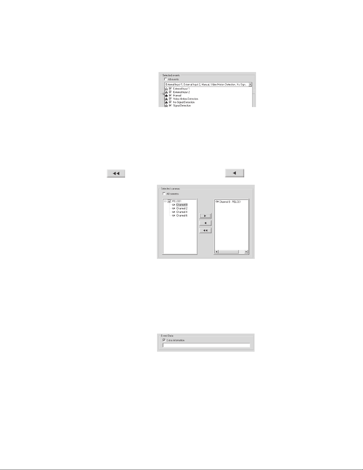
SELECTED EVENTS
To specify the event types to be included in the query:
1. Clear the “All events” checkbox.
2. Select the events you want to include in the query.
Figure 13. Events Query
SELECTED CAMERAS
To specify the cameras to be included in the query:
1. Clear the “All cameras” checkbox.
2. Click the + next to the server name to view the server’s cameras.
3. Double-click the server name to add all cameras to a query or double-click the camera to add a single camera to a query.
4. Click
to remove all cameras or select a camera and click to remove a single camera.
Figure 14. Cameras Query
EVENT DATA
The Extra Information box is used to add information that is received from external systems.
To search by event data:
1. Select the “Extra Information” checkbox.
2. Enter the information in the field.
Figure 15. Event Data
C639M-A (6/04) 17
Page 18
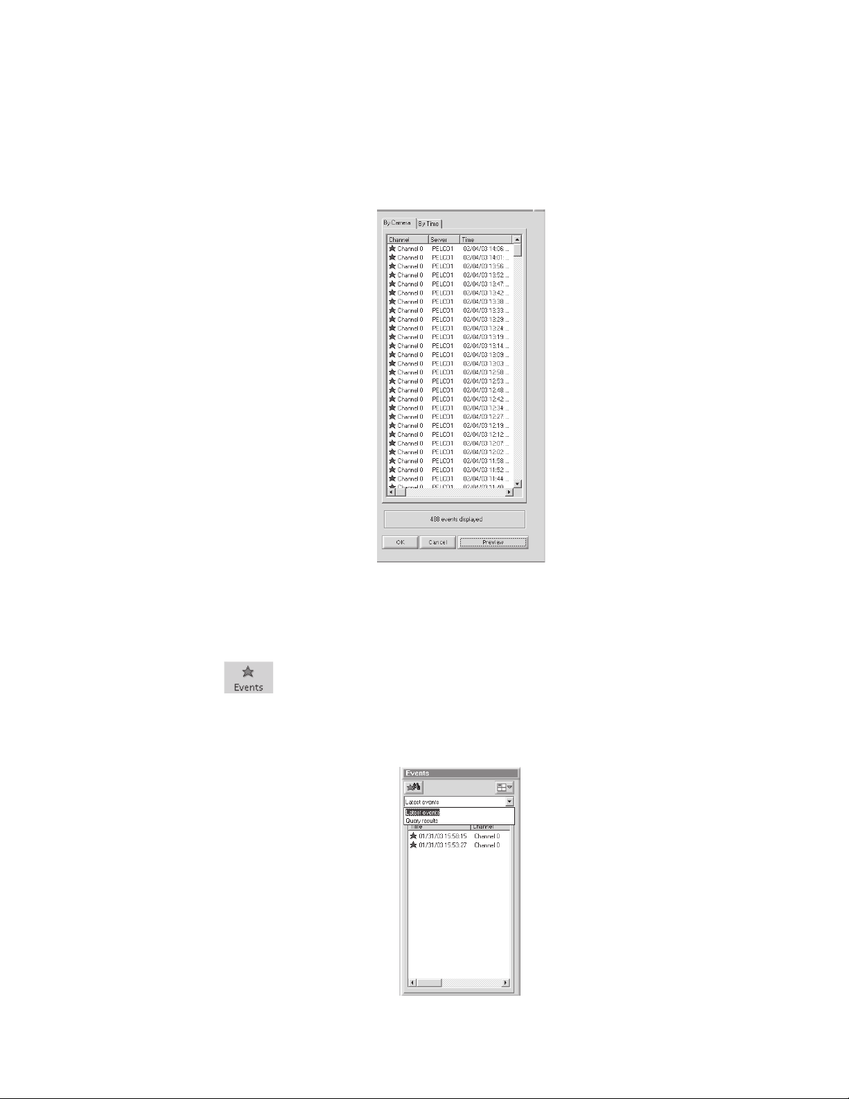
RUNNING THE QUERY
1. Click Preview.
The number of events found appears at the bottom of the Preview Window. The events are arranged in descending order by
server with the latest event at the top of the list. Up to 2,000 events can be displayed. The star color shows the event type.
2. Click the By Camera tab or By Time tab to view the results by camera or by time.
3. Click OK. The events are transferred to the Events Section and the Query Window closes.
CHOOSING FROM THE LATEST EVENTS
The Events Section shows latest events and query results.
1. Click .
2. Select “Latest events.”
3. Select one of the events from the list that appears. An event that has happened in the last 60 seconds plays live video
when dragged into one of the four video windows.
Figure 16. Preview Window
Figure 17. Events Section
18 C639M-A (6/04)
Page 19

MARKING EVENTS
You can mark an event and save it for viewing at a later time.
1. Click
while viewing live or playback video. The video picture enlarges.
Figure 18. Large Screen
Allows you to lock sections of the video and export sections to different media.
Shows events.
Shows the video on the entire screen.
Marks and saves an event. The event is marked in black on the time slider.
Increases or decreases the video playback speed. The red button in the center of the speed meter marks the default
speed. The + sign is 30 times the normal speed. The – sign shows frame-by-frame.
2. Click an event on the time slider.
3. Click
4. Click OK.
5. Click the Zoom Out button or the Zoom In button to see the marked event (black star) on the time slider.
. The following dialog box appears.
Figure 19. Mark Event Dialog Box
C639M-A (6/04) 19
Page 20

SEARCHING FOR MOTION DETECTION
The DX9100 Sherlock feature allows you to scan recorded video forward and backward for movement or disappearance of a
specific object.
1. Playback the video that you want to scan.
2. Click . on the main toolbar is enabled.
3. Click . The Sherlock section appears.
4. Select the Event Type.
• Disappearance: The movement is marked as an event only if the marked object disappears completely from its current
location.
• Any Movement: The movement is marked as an event if the marked object moves from its current location.
Figure 20. Sherlock Section
5. Select scan forward or scan backward.
6. Click the desired object that you want to check for motion. A blue square marks the selected object. You can mark the
object with up to 10 squares.
Figure 21. Marking An Object
20 C639M-A (6/04)
Page 21

7. Click in the Sherlock section.
The clock at the bottom of the Sherlock section displays the current scanning time and “In progress…” appears.
Figure 22. Scan In Progress Message
When the scan detects movement of the selected object, it stops and displays the event. A message with the date and time of
the event appears.
Figure 23. Event Found Dialog Box
NOTE: If you marked more than one object, the first scan shows the first object that moved.
C639M-A (6/04) 21
Page 22

LOCKING/UNLOCKING VIDEO
Locking the video removes the selected section of video from the first in/first out (FIFO) deletion cycle. You can only lock a
section of video and not a current frame.
To lock a video:
1. Click
2. Click . The following window appears.
while viewing live or playback video.
Figure 24. Window for Locking Video
3. Make sure the Video radio button is selected.
4. Select the Start/End date and time. The default is the date and time of the current video.
NOTE: You can also use the time slider to mark a time period. Refer to Figure 29.
5. Click
22 C639M-A (6/04)
. The following dialog box appears.
Page 23

Figure 25. Dialog Box for Reason to Lock Video
6. Enter a reason for locking the selected video and then click OK. The following message appears.
Figure 26. Lock Video Message
Only authorized users can unlock a locked video. This video is returned to the FIFO cycle and is deleted according to its location
in the queue.
To unlock a video:
1. Click
. The Lock section appears.
Figure 27. Lock Section
2. Select the server from the drop-down box. The locked videos appear in the section.
3. Select a locked video.
NOTE: You can view a locked video before unlocking it.
4. Click
or right-click the locked video and then select Unlock Video.
5. Enter a reason and then click OK. The locked video is unlocked and removed from the locked video list.
C639M-A (6/04) 23
Page 24

EXPORTING VIDEO
1. Click while viewing live or playback video.
2. Click
. The following window appears.
Figure 28. Exporting Video Window
3. Select the Video radio button to save a section of video.
4. Select the Start/End date and time. The default is the date and time of the current video.
You can also use the time slider to mark a time period. The selected area is marked in yellow as shown below. You can drag
the beginning/end arrows of the marked time period to increase/decrease the video section.
Figure 29. Time Slider Video Section
5. Select the event types to be shown on the time slider. All events are selected by default.
6. Export the video.
a. Click File to export the video and save it in an MPEG format.
b. Click e-Mail to attach the video in an MPEG format to an e-mail message.
7. Click Close to exit.
NOTE: You can view an exported video at any time using Export Viewer. Refer to the Export Viewer section.
24 C639M-A (6/04)
Page 25

EXPORTING A CURRENT FRAME
1. Click while viewing live or playback video.
2. Click
3. Select the “Current frame” radio button. The following window appears.
.
Figure 30. Exporting Current Frame Window
4. Export the frame.
a. Click File to export the frame and save it in a BMP or JPEG format.
b. Click e-Mail to attach the frame in a JPEG format to an e-mail message.
c. Click Printer to print the frame.
d. Click MS Word to insert the frame into a Word document. The image is saved in a JPEG format.
5. Click Close.
NOTE: The e-Mail and Printer buttons are disabled unless you set up your e-mail and printer. The MS Word button is
disabled if MS Word is not installed.
C639M-A (6/04) 25
Page 26

CAMERA RECORDING PROPERTIES
Camera recording properties should be set by the system administrator during installation. Only system administrators and
operators with a Level 1 authorization can set or change camera recording properties. To set or change camera recording
properties, you must open the DX9000 Viewstation application. The System button on the main toolbar is not available to Level 2-6
operators. If you don’t have access, see the system administrator.
To set or change camera recording properties:
1. Click System > Properties on the main toolbar. The following window appears.
Figure 31. Camera Properties Dialog Box
26 C639M-A (6/04)
Page 27

2. Click “Select channel” to display a list of recorders. An example is shown below.
Figure 32. Select Channel Dialog Box
3. Select a channel.
4. Select the Preview checkbox to verify that you have the correct camera.
Figure 33. Continuous Recording Schedule Page
C639M-A (6/04) 27
Page 28

CONTINUOUS RECORDING SCHEDULE
1. Select the “Continuous recording” radio button. This is the default setting and should be selected already when you
select a channel. Refer to Figure 33.
2. Click Apply.
Recording is done at all times and no schedule is defined. The entire daily and weekly recording schedules are marked in light
yellow, and any previous definitions on the schedules are removed.
DAILY RECORDING SCHEDULE
To make sure there is no delay during scheduled recording, begin the recording at least five minutes before the actual
recording time. For example, schedule the recording at 7:55 a.m. instead of 8:00 a.m.
1. Select the “Daily recording schedule” radio button.
2. Click Continuous or “Event record.”
3. In the time bar, click the desired start/end times for recording, or enter the exact start/end times in the “Fine tune” fields.
4. Click Apply.
The example below shows a
with a red border. You can make the box smaller or larger by dragging it with your mouse.
Continuous
daily recording schedule from 7:05 a.m. to 12:05 p.m. The box in the time bar is blue
Figure 34. Continuous Daily Recording Schedule Page
28 C639M-A (6/04)
Page 29

The example below shows a daily
Event record
schedule from 7:05 a.m. to 12:05 p.m. The box in the time bar is yellow with a
red border. You can make the box smaller or larger by dragging it with your mouse.
Figure 35. Daily Event Recording Page
If you select event recording, the DX9100 actually records continuously. The difference between continuous and event
recording is the way the video is saved in the database. When the hard drives are full, the DX9100 starts overwriting the oldest
video. With continuous recording, the DX9100 overwrites the video in the order in which it was recorded, whether it is an
event or a nonevent. With event recording, the DX9100 overwrites nonevents first and then events. Data is overwritten on a
day-to-day basis.
To delete a time period:
1. Click “No record.”
2. Click the box in the time bar.
C639M-A (6/04) 29
Page 30

WEEKLY RECORDING SCHEDULE
To make sure there is no delay during scheduled recording, begin the recording at least five minutes before the actual recording
time. For example, schedule the recording at 7:55 a.m. instead of 8:00 a.m.
1. Select the “Daily recording schedule” radio button.
2. Click Continuous or “Event record.”
3. In the time bar, click the desired start/end times for recording, or enter the exact start/end times in the “Fine tune” fields.
4. Click Apply.
The example below shows a
blue with a red border. You can make the boxes smaller or larger by dragging them with your mouse.
The example below shows a weekly
with a red border. You can make the boxes smaller or larger by dragging them with your mouse.
Continuous
weekly recording schedule from 7:05 a.m. to 12:05 p.m. The boxes in the time bars are
Figure 36. Continuous Weekly Recording Schedule Page
Event record
schedule from 7:05 a.m. to 12:05 p.m. The boxes in the time bars are yellow
Figure 37. Weekly Event Recording Schedule Page
To delete a time period:
1. Click “No record.”
2. Click a box in a time bar.
30 C639M-A (6/04)
Page 31

MOTION DETECTION
1. Click the DVMD tab.
2. Select the “Detector on” radio button.
3. Select the Preview checkbox. The video has blue squares over the entire area meaning the entire video has been selected
for motion detection.
4. Click “Clear all” to remove all of the boxes, or click the right mouse button on each box you want to remove.
5. Click “Mark all” to select the entire video for motion detection, or click the left mouse button to add individual boxes.
6. Click “Discard changes” to undo your changes.
7. Drag the triangles on the slider bars to select the minimum time between events and the video motion detection (VMD)
sensitivity.
8. Click Apply.
Figure 38. Motion Detection Page
C639M-A (6/04) 31
Page 32

CHANNEL SETUP
This section describes how to set camera properties to get the best picture.
1. Click the Video tab. The Video page appears. Refer to Figure 39.
2. Select the Preview checkbox to see the video quality with the default settings.
3. Adjust the video quality by dragging the triangles on the slider bars to the desired values. Refer to Table B.
4. Click Apply.
NOTE: The bit rate, located under the “Select channel” button, displays the amount of activity in the specified channel. A higher
bit rate requires more storage space. It is important to notice the bit rate as you adjust your camera settings to achieve the highest
quality picture with the lowest bit rate.
Figure 39. Camera Video Setup Page
32 C639M-A (6/04)
Page 33

Table B. Channel Setup
Parameter Description/Action
Channel Name Enter a new name for this channel. You can enter up to 20 characters.
Brightness Drag the triangle to change the brightness value. The higher the value, the higher the bit rate. The
previous value is displayed to the right of the brightness bar.
Contrast Drag the triangle to change the contrast value. The higher the value, the higher the bit rate. The previous
value is displayed to the right of the contrast bar.
Hue Drag the triangle to change the hue value. The previous value is displayed to the right of the hue bar.
Sat V Drag the triangle to increase or decrease the red color in the video. The previous value is displayed to the
right of the Sat V bar.
Sat U Drag the triangle to increase or decrease the blue color in the video. The previous value is displayed to
the right of the Sat U bar.
Vertical This reduces or eliminates video noise. The higher the value, the lower the bit rate. The lower the value,
the higher the bit rate.
Horizontal This reduces or eliminates video noise. The higher the value, the lower the bit rate. The lower the value,
the higher the bit rate.
Black/White Select this checkbox if the channel is connected to a black/white camera. This option ignores video
noise.
White Crush Select this checkbox to reduce the intensity of the white images.
C639M-A (6/04) 33
Page 34

DEFINING USERS
Only system administrators can define user names and passwords for the DX9100 Viewstation. Other users trying to access
this option will get the following message:
This option allows an administrator to add, delete, and change the properties of users in the DX9100 system. There are seven
predefined user access levels ranging from Administrator to Operator Level 6. Each user is assigned different access rights to
the DX9100 network and videos.
Click System > Users on the main toolbar. In the example below, each operator level has been assigned a user name and
password.
Figure 40. User Access Message Box
Figure 41 . User Manager Dialog Box
34 C639M-A (6/04)
Page 35

Table C. User Access Rights
Video Locked Export Unlock Video/ Define
Live Video/ Playback/ Video Lock Image/ Change Camera Users/Audit
User Live Events Query/Sherlock Playback Video Video Settings Viewer
Administrator ✓✓✓✓✓✓✓
Operator Level 1 ✓✓✓✓✓✓
Operator Level 2 ✓✓✓✓✓
Operator Level 3 ✓✓✓✓
Operator Level 4 ✓✓✓
Operator Level 5 ✓✓
Operator Level 6 ✓
Edit Existing Users
1. Select the server name from the “Filter per server” drop-down box. A list of users defined for the selected server appears
under the Users List.
2. Select a user. The user’s properties appear in the Properties panel.
3. Select a new operator authorization level.
4. Select the server name from the “Accessible servers list.”
5. Click OK.
Adding a New User
1. Click New.
2. Enter the user name. This is the login user name.
3. Enter the user’s full name.
4. Enter the user’s password. This is the login password.
5. Re-enter the same password.
6. Select the user’s authorization level: administrator or operator.
7. Highlight the server the user should have access to from the “Accessible servers list.”
8. Click OK.
Deleting a User
1. Select the user name from the “Users list.”
2. Select the server name from the “Accessible servers list.”
3. Click the left arrow button.
4. Click OK.
C639M-A (6/04) 35
Page 36

ADVANCED FEATURES
AUDIT VIEWER
This is an external software application that is supplied with DX9000 systems. Before using this application, make sure you
exit the viewstation application. This application audits every movement by the user in the system regardless of user access
rights. All records include category type, time and date of operation, viewstation, and user login ID. For any report generated
by the Audit Viewer, there is a maximum of 2,000 records per recorder.
1. Go to Start > Programs > DX9000 Viewstation > Audit Viewer. The following dialog box appears.
2. Enter your “User name” and Password and then click OK. The following window appears.
Figure 42. Audit Viewer Login Dialog Box
Figure 43. Audit Viewer Window
36 C639M-A (6/04)
Page 37

Icon Description
This is the Create New Report icon. Click to modify columns, define filters, and sort columns.
This is the Save icon. Click to save the audit report. You can save the report as an HTML, PDF, or TXT file type.
This is the Refresh icon. Click to refresh the audit report.
This is the Print icon. Click to print the audit report.
This is the About icon. Click to display the Audit Viewer version number.
Table D. Audit Viewer Toolbar
C639M-A (6/04) 37
Page 38

CREATING REPORTS
You must define filters before you create a new report. You can define the category, user name, date and time, and computer
name. You can also modify columns and sort columns.
1. Go to File > Create Report, or click the Create New Report icon. The following page appears.
Figure 44. Modify Columns Page
2. Add or Remove the columns you want to appear on your report.
3. Click the Filter tab. The following page appears.
Figure 45. Filter Page
38 C639M-A (6/04)
Page 39

4. Click the yellow icon next to Categories. The following dialog box appears.
Figure 46. Select Category Dialog Box
5. Add or remove categories and then click OK.
6. Click the yellow icon next to Users. The following dialog box appears.
Figure 47. Select Users Dialog Box
7. Add or remove users and then click OK.
C639M-A (6/04) 39
Page 40

8. Click the yellow icon next to Servers. The following dialog box appears.
Figure 48. Select Servers Dialog Box
9. Add or remove servers and then click OK.
10. Click the yellow icon next to Date & Time. The following dialog box appears.
Figure 49. Select Date & Time Dialog Box
11. Select the date and time range and then click OK.
12. Click the yellow icon next to Viewstations. The following dialog box appears.
Figure 50. Select Viewstations Dialog Box
40 C639M-A (6/04)
Page 41

13. Add or remove viewstations and then click OK.
14. Click the Order tab. The following page appears.
Figure 51. Order Page
15. Change the order of the filter settings. You can move them up or down or in ascending or descending order.
16. Click Create. An example of an audit report is shown in Figure 52.
Figure 52. Sample Audit Report
NOTE: The Event Time is the local time. The time in the Description column is UTC time.
C639M-A (6/04) 41
Page 42

EXPORT VIEWER
The Export Viewer allows you to view exported videos without the DX9000 viewstation.
1. Go to Start > Programs > DX9000 Viewstation > Export Viewer. The following window appears.
Figure 53. Export Viewer Window
2. Click Open. The following dialog box appears.
Figure 54. Open Video File Dialog Box
3. Select the file you want to view.
42 C639M-A (6/04)
Page 43

4. Click Open. The video plays automatically. Refer to Figure 55.
Figure 55. Video Playback
The date and time of the video is displayed below the video play bar. The speed control allows you to change the speed at
which the video is played. The 0 represents normal speed. Click to view the video on the entire screen.
C639M-A (6/04) 43
Page 44

VIDEO VERIFIER
This is an external software application that is supplied with DX9000 systems. It allows you to verify the authenticity of
recorded video by identifying if and where an image or segment of video was changed.
You can only browse and verify files that have been exported as MPEG files.
NOTE: When you export a video and want to write the data onto a CD, make sure you copy Video Verifier to the same directory
as the exported video.
1. Go to Start > Programs > DX9000 Viewstation > Video Verifier.
Once the application opens, the following window appears.
Figure 56. Video Originality Verifier Window
2. Enter the path name of the video file, or click Browse to locate the file.
44 C639M-A (6/04)
Page 45

3. Select the video file and then click Open.
Figure 57. Open Verifier File Dialog Box
4. Verification starts automatically. The following preview window shows the first frame of the video being tested.
Figure 58. Verifier Information Window
C639M-A (6/04) 45
Page 46

Table E. Verifier Information Panel
Name Description/Action
Bit Exact Tests:
File structure Checks the syntax of the video file.
Integrity watermark Checks that bits in the video file have not been deleted or modified.
Authentication watermark Checks the time and date inside the video stream.
Video Originality:
Ownership DX9000 Server.
Video starting date Starting date of the original video.
Video starting time Starting time of the original video.
NTSC/PAL Video standard of the original video.
Tested File Info:
Name File name of the tested video file.
Size Size of the tested video file in bytes.
Verification Information:
Date Date of the test.
Time Time of the test.
Version Version of the Video Verifier application.
If the test is unsuccessful, the following information appears in the Verifier Information panel.
Figure 59. Failed File Structure Message
46 C639M-A (6/04)
Page 47

Table F. Failed Test Information
Name Description
Bit Exact Tests:
File structure Indicates that the test has failed.
Tested File Info:
Name Name of the tested video file.
Size Size of the tested video file in bytes.
Verification Information:
Date Date of the test.
Time Time of the test.
Version Version of the Video Verifier application.
You can do the following from the Video Verifier window.
Table G. Video Verifier Buttons
Button Action
Start Click to rerun a test.
About Click to see the DX9000 Bit Exact Video Originality Verifier window.
Help Click to read an overview on Bit Exact Integrity and Authentication Watermark.
Print Click to print the Verifier Information results.
Save As Click to save the results as a text (.txt) file.
Clear Click to clear the window of the results.
C639M-A (6/04) 47
Page 48

MAKING A CD OR DVD
You can use Nero® to copy data, such as exported video files, onto a CD or DVD. The following steps show how to copy a
folder onto a CD.
1. Insert a blank CD into your CD-RW drive.
2. Double-click the Nero StartSmart icon on your desktop. The following window appears.
Figure 60. Welcome Window
3. Click CD, and then select the data icon next to the star.
Figure 61. Data Window
48 C639M-A (6/04)
Page 49

4. Click Make Data Disc. The following window appears
5. Click Add. The following window appears.
Figure 63. Select Files and Folders Window
Figure 62. Add Files Window
C639M-A (6/04) 49
Page 50

6. Select a file or folder, and then click Add. Figure 63 shows a DX9100 folder.
7. Click Next. The following window appears.
Figure 64. Added File Window
Figure 65. Final Burn Settings Window
50 C639M-A (6/04)
Page 51

8. Click Burn. The following dialog box appears when the burn process is completed successfully.
Figure 66. Data Verification Dialog Box
9. Click OK.
Figure 67. Burning Process Window
C639M-A (6/04) 51
Page 52

10. Click Next. The following window appears.
11. Click Exit.
Figure 68. Exit Window
52 C639M-A (6/04)
Page 53

SERVER STATE
The Server State utility checks the status of the recorders that are connected to the viewstation. It verifies if a recorder is
recording, not recording, or unreachable. The Server State application should be running in the background all the time.
1. Go to Start > Programs > DX9000 Viewstation > Server State.
Figure 69. Server State
2. Select “All servers” to run the test on all recorders or Server to run the test on a specific recorder.
3. Click Configure. The following dialog box appears.
Figure 70. Configuration Options
C639M-A (6/04) 53
Page 54

4. Select the refresh interval. The recommended setting is 60 seconds. Any setting less than 60 seconds will become
network intensive because the viewstation constantly polls the recorders.
5. Click OK.
6. Check the “Auto-refresh” checkbox. The application checks the refresh interval when you click start.
7. Check the “Alert on errors or warning” checkbox. The following message appears when an error occurs.
Figure 71. Error Alert Message
NOTE: Checking the “Alert on errors or warning” checkbox activates the serveralert.exe file in C:\Viewstation\Config.
You can replace this file with a batch (.bat) file that can send a text message to any other computer. The batch file must
be called serveralert.bat.
8. Click Start. The following table explains the symbols that appear next to the server name.
Table H. Server State Symbols
Symbol Status
Status is not known. The server has not been tested yet.
Test in progress. This arrow appears next to each server being tested.
The server is working.
Server alert. The error alert message above appears. The error results appear in the bottom right panel.
Alerts you to a server problem even thought the server is still recording.
54 C639M-A (6/04)
Page 55

ONLINE STORAGE METER
The Online Storage Meter measures how much storage a group of cameras is using in a specific time frame.
1. Go to Start > Programs > DX9000 Viewstation > Online Storage Meter.
2. Enter the Server name and the Channel number.
3. Select a specific time frame.
4. Select the graph type.
5. Click Show.
Figure 72. Online Storage Meter
Figure 73. Storage Consumption Graph
C639M-A (6/04) 55
Page 56

WARRANTY AND RETURN INFORMATION
WARRANTY
Pelco will repair or replace, without charge, any merchandise proved defective in material
or workmanship for a period of one year after the date of shipment.
Exceptions to this warranty are as noted below:
• Five years on the following fixed camera models: CC3701H-2, CC3701H-2X, CC3751H-2,
CC3651H-2X, MC3651H-2, and MC3651H-2X.
• Three years on all fixed camera models (including Camclosure® Integrated Camera
Systems) and Genex® Series (multiplexers, server, and keyboard).
•Two years on all other standard motorized or fixed focal length lenses.
•Two years on Legacy®, CM6700/CM6800/CM8500/CM9500/CM9700 Series Matrix,
DF5 and DF8 Series Fixed Dome products.
•Two years on Spectra®, Esprit®, and PS20 Scanners, including when used in continuous
motion applications.
•Two years on Esprit® and WW5700 series window wiper (excluding wiper blades).
• Eighteen months on DX Series digital video recorders and NVR300 network video
recorders.
• One year (except video heads) on video cassette recorders (VCRs). Video heads will be
covered for a period of six months.
• Six months on all pan and tilts, scanners or preset lenses used in continuous motion
applications (that is, preset scan, tour and auto scan modes).
Pelco will warrant all replacement parts and repairs for 90 days from the date of Pelco
shipment. All goods requiring warranty repair shall be sent freight prepaid to Pelco, Clovis,
California. Repairs made necessary by reason of misuse, alteration, normal wear, or
accident are not covered under this warranty.
Pelco assumes no risk and shall be subject to no liability for damages or loss resulting from
the specific use or application made of the Products. Pelco’s liability for any claim, whether
based on breach of contract, negligence, infringement of any rights of any party or product
liability, relating to the Products shall not exceed the price paid by the Dealer to Pelco for
such Products. In no event will Pelco be liable for any special, incidental or consequential
damages (including loss of use, loss of profit and claims of third parties) however caused,
whether by the negligence of Pelco or otherwise.
The above warranty provides the Dealer with specific legal rights. The Dealer may also
have additional rights, which are subject to variation from state to state.
If a warranty repair is required, the Dealer must contact Pelco at (800) 289-9100 or (559) 292-1981
to obtain a Repair Authorization number (RA), and provide the following information:
1. Model and serial number
2. Date of shipment, P.O. number, Sales Order number, or Pelco invoice number
3. Details of the defect or problem
If there is a dispute regarding the warranty of a product which does not fall under the warranty
conditions stated above, please include a written explanation with the product when returned.
Method of return shipment shall be the same or equal to the method by which the item was
received by Pelco.
RETURNS
In order to expedite parts returned to the factory for repair or credit, please call the factory at (800)
289-9100 or (559) 292-1981 to obtain an authorization number (CA number if returned for credit,
and RA number if returned for repair).
All merchandise returned for credit may be subject to a 20% restocking and refurbishing charge.
Goods returned for repair or credit should be clearly identified with the assigned CA or RA number
and freight should be prepaid. Ship to the appropriate address below.
If you are located within the continental U.S., Alaska, Hawaii or Puerto Rico, send goods to:
Service Department
Pelco
3500 Pelco Way
Clovis, CA 93612-5699
If you are located outside the continental U.S., Alaska, Hawaii or Puerto Rico and are instructed to
return goods to the USA, you may do one of the following:
If the goods are to be sent by a COURIER
SERVICE, send the goods to:
Pelco
3500 Pelco Way
Clovis, CA 93612-5699 USA
If the goods are to be sent by a FREIGHT
FORWARDER, send the goods to:
Pelco c/o Expeditors
473 Eccles Avenue
South San Francisco, CA 94080 USA
Phone: 650-737-1700
Fax: 650-737-0933
REVISION HISTORY
Manual # Date Comments
C639M 9/03 Original version.
C639M-A 6/04 Revised
® Pelco, the Pelco logo, Spectra, Genex, Esprit, Camclosure, and Legacy are registered trademarks of Pelco. © Copyright 2003, Pelco. All rights reserved.
® Nero is a registered trademark of Ahead Software.
56 C639M-A (6/04)
Making a CD
section
.
Page 57

®
World Headquarters
3500 Pelco Way
Clovis, California 93612 USA
USA & Canada
Tel: 800/289-9100
Fax: 800/289-9150
International
Tel: 1-559/292-1981
Fax: 1-559/348-1120
www.pelco.com
ISO9001
United States | Canada | United Kingdom | The Netherlands | Singapore | Spain | Scandinavia | France | Middle East
C639M-A (6/04) 57
Page 58

 Loading...