

Page 1

Client Applications Manual
DX8000
Digital Video Recorder C626M-B (3/05)
Page 2

Protecting people and property in a million locations worldwide.
Page 3

Contents
DX8000 PC Client Software . . . . . . . . . . . . . . . . . . . . . . . . . . . . . . . . . . . . . . . . . . . . . . . . . . . . . . . . . . . . . . . . . . . . . . . . . . . . . . . . . . . . . . . . . . . .13
Description . . . . . . . . . . . . . . . . . . . . . . . . . . . . . . . . . . . . . . . . . . . . . . . . . . . . . . . . . . . . . . . . . . . . . . . . . . . . . . . . . . . . . . . . . . . . . . . . . . . . .13
Recommended System Requirements . . . . . . . . . . . . . . . . . . . . . . . . . . . . . . . . . . . . . . . . . . . . . . . . . . . . . . . . . . . . . . . . . . . . . . . . . . . . . . . .13
Installing the PC Client Application . . . . . . . . . . . . . . . . . . . . . . . . . . . . . . . . . . . . . . . . . . . . . . . . . . . . . . . . . . . . . . . . . . . . . . . . . . . . . . . . . .13
Enabling IPSec Security Services . . . . . . . . . . . . . . . . . . . . . . . . . . . . . . . . . . . . . . . . . . . . . . . . . . . . . . . . . . . . . . . . . . . . . . . . . . . . . . . . . . .16
Disabling IPSec Security Services . . . . . . . . . . . . . . . . . . . . . . . . . . . . . . . . . . . . . . . . . . . . . . . . . . . . . . . . . . . . . . . . . . . . . . . . . . . . . . . . . . . 16
Before You Begin . . . . . . . . . . . . . . . . . . . . . . . . . . . . . . . . . . . . . . . . . . . . . . . . . . . . . . . . . . . . . . . . . . . . . . . . . . . . . . . . . . . . . . . . . . . . . . . . . . . .17
Starting the DX8000 PC Client Application . . . . . . . . . . . . . . . . . . . . . . . . . . . . . . . . . . . . . . . . . . . . . . . . . . . . . . . . . . . . . . . . . . . . . . . . . . . . . . . . 18
Automatic System Upgrade . . . . . . . . . . . . . . . . . . . . . . . . . . . . . . . . . . . . . . . . . . . . . . . . . . . . . . . . . . . . . . . . . . . . . . . . . . . . . . . . . . . . . . . .18
PC Client Application Log-In . . . . . . . . . . . . . . . . . . . . . . . . . . . . . . . . . . . . . . . . . . . . . . . . . . . . . . . . . . . . . . . . . . . . . . . . . . . . . . . . . . . . . . . . . . . .19
Enabling DirectDraw Video Hardware Acceleration . . . . . . . . . . . . . . . . . . . . . . . . . . . . . . . . . . . . . . . . . . . . . . . . . . . . . . . . . . . . . . . . . . . . . . . . . 21
Connecting to DX8000 DVR Server Sites . . . . . . . . . . . . . . . . . . . . . . . . . . . . . . . . . . . . . . . . . . . . . . . . . . . . . . . . . . . . . . . . . . . . . . . . . . . . . . . . . .22
Adding a DX8000 DVR Server to the Connection List . . . . . . . . . . . . . . . . . . . . . . . . . . . . . . . . . . . . . . . . . . . . . . . . . . . . . . . . . . . . . . . . . . . . 22
Deleting a DX8000 DVR Server from the Connection List . . . . . . . . . . . . . . . . . . . . . . . . . . . . . . . . . . . . . . . . . . . . . . . . . . . . . . . . . . . . . . . . .24
Editing a DX8000 Server’s Information from the Connection List . . . . . . . . . . . . . . . . . . . . . . . . . . . . . . . . . . . . . . . . . . . . . . . . . . . . . . . . . . .25
Connecting to a Remote Site . . . . . . . . . . . . . . . . . . . . . . . . . . . . . . . . . . . . . . . . . . . . . . . . . . . . . . . . . . . . . . . . . . . . . . . . . . . . . . . . . . . . . . .26
Logging In to a Remote Site . . . . . . . . . . . . . . . . . . . . . . . . . . . . . . . . . . . . . . . . . . . . . . . . . . . . . . . . . . . . . . . . . . . . . . . . . . . . . . . . . . . . . . .26
Logging Out of a Remote Site . . . . . . . . . . . . . . . . . . . . . . . . . . . . . . . . . . . . . . . . . . . . . . . . . . . . . . . . . . . . . . . . . . . . . . . . . . . . . . . . . . . . . .27
Disconnecting from a Remote Site . . . . . . . . . . . . . . . . . . . . . . . . . . . . . . . . . . . . . . . . . . . . . . . . . . . . . . . . . . . . . . . . . . . . . . . . . . . . . . . . . .28
Exiting the DX8000 PC Client Application . . . . . . . . . . . . . . . . . . . . . . . . . . . . . . . . . . . . . . . . . . . . . . . . . . . . . . . . . . . . . . . . . . . . . . . . . . . . . 28
Description of Operating Modes . . . . . . . . . . . . . . . . . . . . . . . . . . . . . . . . . . . . . . . . . . . . . . . . . . . . . . . . . . . . . . . . . . . . . . . . . . . . . . . . . . . . . . . .29
DX8000 PC Client Application Main Screen . . . . . . . . . . . . . . . . . . . . . . . . . . . . . . . . . . . . . . . . . . . . . . . . . . . . . . . . . . . . . . . . . . . . . . . . . . . . . . . .30
Working with the Site Tree . . . . . . . . . . . . . . . . . . . . . . . . . . . . . . . . . . . . . . . . . . . . . . . . . . . . . . . . . . . . . . . . . . . . . . . . . . . . . . . . . . . . . . . .31
Assigning Cameras to View Panels . . . . . . . . . . . . . . . . . . . . . . . . . . . . . . . . . . . . . . . . . . . . . . . . . . . . . . . . . . . . . . . . . . . . . . . . . . . . .32
Linking Alarm Inputs and Relay Outputs to Cameras . . . . . . . . . . . . . . . . . . . . . . . . . . . . . . . . . . . . . . . . . . . . . . . . . . . . . . . . . . . . . . . .33
Linking Relay Outputs to Alarm Inputs . . . . . . . . . . . . . . . . . . . . . . . . . . . . . . . . . . . . . . . . . . . . . . . . . . . . . . . . . . . . . . . . . . . . . . . . . . . 36
Removing a Linked Alarm Input from a Camera . . . . . . . . . . . . . . . . . . . . . . . . . . . . . . . . . . . . . . . . . . . . . . . . . . . . . . . . . . . . . . . . . . . .37
Removing a Linked Relay Output from a Camera . . . . . . . . . . . . . . . . . . . . . . . . . . . . . . . . . . . . . . . . . . . . . . . . . . . . . . . . . . . . . . . . . . .38
Removing a Linked Relay Output from an Alarm Input . . . . . . . . . . . . . . . . . . . . . . . . . . . . . . . . . . . . . . . . . . . . . . . . . . . . . . . . . . . . . .39
Understanding View Panels and Windows . . . . . . . . . . . . . . . . . . . . . . . . . . . . . . . . . . . . . . . . . . . . . . . . . . . . . . . . . . . . . . . . . . . . . . . . . . . . 40
Configuring View Panels . . . . . . . . . . . . . . . . . . . . . . . . . . . . . . . . . . . . . . . . . . . . . . . . . . . . . . . . . . . . . . . . . . . . . . . . . . . . . . . . . . . . . .41
Navigating Between View Windows . . . . . . . . . . . . . . . . . . . . . . . . . . . . . . . . . . . . . . . . . . . . . . . . . . . . . . . . . . . . . . . . . . . . . . . . . . . .42
Live View Mode . . . . . . . . . . . . . . . . . . . . . . . . . . . . . . . . . . . . . . . . . . . . . . . . . . . . . . . . . . . . . . . . . . . . . . . . . . . . . . . . . . . . . . . . . . . . . . . . . . . . .43
Assigning Cameras to View Panels . . . . . . . . . . . . . . . . . . . . . . . . . . . . . . . . . . . . . . . . . . . . . . . . . . . . . . . . . . . . . . . . . . . . . . . . . . . . . . . . . .43
Live View On-Screen Display (OSD) . . . . . . . . . . . . . . . . . . . . . . . . . . . . . . . . . . . . . . . . . . . . . . . . . . . . . . . . . . . . . . . . . . . . . . . . . . . . . . . . .44
Customizing the On-Screen Display (OSD) . . . . . . . . . . . . . . . . . . . . . . . . . . . . . . . . . . . . . . . . . . . . . . . . . . . . . . . . . . . . . . . . . . . . . . . . . . . . 45
Instant Recording . . . . . . . . . . . . . . . . . . . . . . . . . . . . . . . . . . . . . . . . . . . . . . . . . . . . . . . . . . . . . . . . . . . . . . . . . . . . . . . . . . . . . . . . . . . . . . . .45
Enabling and Disabling . . . . . . . . . . . . . . . . . . . . . . . . . . . . . . . . . . . . . . . . . . . . . . . . . . . . . . . . . . . . . . . . . . . . . . . . . . . . . . . . . . . . . . . 45
Adding Instant Recording to OSD . . . . . . . . . . . . . . . . . . . . . . . . . . . . . . . . . . . . . . . . . . . . . . . . . . . . . . . . . . . . . . . . . . . . . . . . . . . . . . .46
Activating And Deactivating Instant Recording . . . . . . . . . . . . . . . . . . . . . . . . . . . . . . . . . . . . . . . . . . . . . . . . . . . . . . . . . . . . . . . . . . . .46
Operating the On-Screen Pan, Tilt, and Zoom (PTZ) Controls . . . . . . . . . . . . . . . . . . . . . . . . . . . . . . . . . . . . . . . . . . . . . . . . . . . . . . . . . . . . . .47
Using PC Keyboard Shortcuts to Operate PTZ and Lens Functions . . . . . . . . . . . . . . . . . . . . . . . . . . . . . . . . . . . . . . . . . . . . . . . . . . . . . . . . . .49
PTZ Presets . . . . . . . . . . . . . . . . . . . . . . . . . . . . . . . . . . . . . . . . . . . . . . . . . . . . . . . . . . . . . . . . . . . . . . . . . . . . . . . . . . . . . . . . . . . . . . . . . . . .50
Programming a Preset . . . . . . . . . . . . . . . . . . . . . . . . . . . . . . . . . . . . . . . . . . . . . . . . . . . . . . . . . . . . . . . . . . . . . . . . . . . . . . . . . . . . . . . .50
Activating a Preset . . . . . . . . . . . . . . . . . . . . . . . . . . . . . . . . . . . . . . . . . . . . . . . . . . . . . . . . . . . . . . . . . . . . . . . . . . . . . . . . . . . . . . . . . .52
Clearing a Preset . . . . . . . . . . . . . . . . . . . . . . . . . . . . . . . . . . . . . . . . . . . . . . . . . . . . . . . . . . . . . . . . . . . . . . . . . . . . . . . . . . . . . . . . . . . .52
PTZ Patterns . . . . . . . . . . . . . . . . . . . . . . . . . . . . . . . . . . . . . . . . . . . . . . . . . . . . . . . . . . . . . . . . . . . . . . . . . . . . . . . . . . . . . . . . . . . . . . . . . . . .53
Programming a Pattern . . . . . . . . . . . . . . . . . . . . . . . . . . . . . . . . . . . . . . . . . . . . . . . . . . . . . . . . . . . . . . . . . . . . . . . . . . . . . . . . . . . . . . . 53
Activating a Pattern . . . . . . . . . . . . . . . . . . . . . . . . . . . . . . . . . . . . . . . . . . . . . . . . . . . . . . . . . . . . . . . . . . . . . . . . . . . . . . . . . . . . . . . . . 54
Clearing a Pattern . . . . . . . . . . . . . . . . . . . . . . . . . . . . . . . . . . . . . . . . . . . . . . . . . . . . . . . . . . . . . . . . . . . . . . . . . . . . . . . . . . . . . . . . . . . 54
Accessing Programming Features of Remote Cameras . . . . . . . . . . . . . . . . . . . . . . . . . . . . . . . . . . . . . . . . . . . . . . . . . . . . . . . . . . . . . .55
C626M-B (3/05) 3
Page 4

Sending Auxiliary Commands to a Device . . . . . . . . . . . . . . . . . . . . . . . . . . . . . . . . . . . . . . . . . . . . . . . . . . . . . . . . . . . . . . . . . . . . . . . . . . . . .57
Configuring Preset Tours . . . . . . . . . . . . . . . . . . . . . . . . . . . . . . . . . . . . . . . . . . . . . . . . . . . . . . . . . . . . . . . . . . . . . . . . . . . . . . . . . . . . . . . . . .58
Programming Preset Tours . . . . . . . . . . . . . . . . . . . . . . . . . . . . . . . . . . . . . . . . . . . . . . . . . . . . . . . . . . . . . . . . . . . . . . . . . . . . . . . . . . . .58
Activating a Preset Tour . . . . . . . . . . . . . . . . . . . . . . . . . . . . . . . . . . . . . . . . . . . . . . . . . . . . . . . . . . . . . . . . . . . . . . . . . . . . . . . . . . . . . .61
Deactivating a Preset Tour . . . . . . . . . . . . . . . . . . . . . . . . . . . . . . . . . . . . . . . . . . . . . . . . . . . . . . . . . . . . . . . . . . . . . . . . . . . . . . . . . . . .61
Playback Mode . . . . . . . . . . . . . . . . . . . . . . . . . . . . . . . . . . . . . . . . . . . . . . . . . . . . . . . . . . . . . . . . . . . . . . . . . . . . . . . . . . . . . . . . . . . . . . . . . . . . . .62
Accessing Playback Mode . . . . . . . . . . . . . . . . . . . . . . . . . . . . . . . . . . . . . . . . . . . . . . . . . . . . . . . . . . . . . . . . . . . . . . . . . . . . . . . . . . . . . . . . . 62
Assigning Cameras to View Panels . . . . . . . . . . . . . . . . . . . . . . . . . . . . . . . . . . . . . . . . . . . . . . . . . . . . . . . . . . . . . . . . . . . . . . . . . . . . . . . . . .62
Playback On-Screen Display (OSD) . . . . . . . . . . . . . . . . . . . . . . . . . . . . . . . . . . . . . . . . . . . . . . . . . . . . . . . . . . . . . . . . . . . . . . . . . . . . . . . . . .63
Playback Controls . . . . . . . . . . . . . . . . . . . . . . . . . . . . . . . . . . . . . . . . . . . . . . . . . . . . . . . . . . . . . . . . . . . . . . . . . . . . . . . . . . . . . . . . . . . . . . . .63
Playback Timeline . . . . . . . . . . . . . . . . . . . . . . . . . . . . . . . . . . . . . . . . . . . . . . . . . . . . . . . . . . . . . . . . . . . . . . . . . . . . . . . . . . . . . . . . . . . . . . . 64
Playing Back Video by Time . . . . . . . . . . . . . . . . . . . . . . . . . . . . . . . . . . . . . . . . . . . . . . . . . . . . . . . . . . . . . . . . . . . . . . . . . . . . . . . . . . . . . . . .65
Instant Replay . . . . . . . . . . . . . . . . . . . . . . . . . . . . . . . . . . . . . . . . . . . . . . . . . . . . . . . . . . . . . . . . . . . . . . . . . . . . . . . . . . . . . . . . . . . . . . 65
Playing Back Video by Event . . . . . . . . . . . . . . . . . . . . . . . . . . . . . . . . . . . . . . . . . . . . . . . . . . . . . . . . . . . . . . . . . . . . . . . . . . . . . . . . . . . . . . .66
Operating Playback Digital Zoom . . . . . . . . . . . . . . . . . . . . . . . . . . . . . . . . . . . . . . . . . . . . . . . . . . . . . . . . . . . . . . . . . . . . . . . . . . . . . . . . . . .68
Zoom Using the Digital Zoom Control . . . . . . . . . . . . . . . . . . . . . . . . . . . . . . . . . . . . . . . . . . . . . . . . . . . . . . . . . . . . . . . . . . . . . . . . . . .68
Zoom Using the Mouse . . . . . . . . . . . . . . . . . . . . . . . . . . . . . . . . . . . . . . . . . . . . . . . . . . . . . . . . . . . . . . . . . . . . . . . . . . . . . . . . . . . . . . .69
Panning a Zoomed Image . . . . . . . . . . . . . . . . . . . . . . . . . . . . . . . . . . . . . . . . . . . . . . . . . . . . . . . . . . . . . . . . . . . . . . . . . . . . . . . . . . . . .70
Viewing Video in the Deinterlaced Mode . . . . . . . . . . . . . . . . . . . . . . . . . . . . . . . . . . . . . . . . . . . . . . . . . . . . . . . . . . . . . . . . . . . . . . . . . . . . .70
Viewing Live and Playback Video Simultaneously . . . . . . . . . . . . . . . . . . . . . . . . . . . . . . . . . . . . . . . . . . . . . . . . . . . . . . . . . . . . . . . . . . . . . . . . . . . 71
Search Mode . . . . . . . . . . . . . . . . . . . . . . . . . . . . . . . . . . . . . . . . . . . . . . . . . . . . . . . . . . . . . . . . . . . . . . . . . . . . . . . . . . . . . . . . . . . . . . . . . . . . . . . .72
Search Screen . . . . . . . . . . . . . . . . . . . . . . . . . . . . . . . . . . . . . . . . . . . . . . . . . . . . . . . . . . . . . . . . . . . . . . . . . . . . . . . . . . . . . . . . . . . . . . . . . .72
Index Video Search . . . . . . . . . . . . . . . . . . . . . . . . . . . . . . . . . . . . . . . . . . . . . . . . . . . . . . . . . . . . . . . . . . . . . . . . . . . . . . . . . . . . . . . . . . . . . . 73
Thumbnail Video Search . . . . . . . . . . . . . . . . . . . . . . . . . . . . . . . . . . . . . . . . . . . . . . . . . . . . . . . . . . . . . . . . . . . . . . . . . . . . . . . . . . . . . . . . . .75
Pixel Video Search . . . . . . . . . . . . . . . . . . . . . . . . . . . . . . . . . . . . . . . . . . . . . . . . . . . . . . . . . . . . . . . . . . . . . . . . . . . . . . . . . . . . . . . . . . . . . . . 78
Viewing and Searching Backed Up Video . . . . . . . . . . . . . . . . . . . . . . . . . . . . . . . . . . . . . . . . . . . . . . . . . . . . . . . . . . . . . . . . . . . . . . . . . . . . . . . . .80
Exporting Video . . . . . . . . . . . . . . . . . . . . . . . . . . . . . . . . . . . . . . . . . . . . . . . . . . . . . . . . . . . . . . . . . . . . . . . . . . . . . . . . . . . . . . . . . . . . . . . . . . . . . .82
Exporting Bookmarked Video Regions . . . . . . . . . . . . . . . . . . . . . . . . . . . . . . . . . . . . . . . . . . . . . . . . . . . . . . . . . . . . . . . . . . . . . . . . . . . . . . . .82
Creating Bookmarks . . . . . . . . . . . . . . . . . . . . . . . . . . . . . . . . . . . . . . . . . . . . . . . . . . . . . . . . . . . . . . . . . . . . . . . . . . . . . . . . . . . . . . . . .82
Clearing Bookmarks . . . . . . . . . . . . . . . . . . . . . . . . . . . . . . . . . . . . . . . . . . . . . . . . . . . . . . . . . . . . . . . . . . . . . . . . . . . . . . . . . . . . . . . . . 83
Inserting and Removing a USB Flash Drive . . . . . . . . . . . . . . . . . . . . . . . . . . . . . . . . . . . . . . . . . . . . . . . . . . . . . . . . . . . . . . . . . . . . . . . . . . . . 84
Installing a USB Flash Drive . . . . . . . . . . . . . . . . . . . . . . . . . . . . . . . . . . . . . . . . . . . . . . . . . . . . . . . . . . . . . . . . . . . . . . . . . . . . . . . . . . .84
Removing a USB Flash Drive . . . . . . . . . . . . . . . . . . . . . . . . . . . . . . . . . . . . . . . . . . . . . . . . . . . . . . . . . . . . . . . . . . . . . . . . . . . . . . . . . .84
Enabling the Deinterlacing Filter . . . . . . . . . . . . . . . . . . . . . . . . . . . . . . . . . . . . . . . . . . . . . . . . . . . . . . . . . . . . . . . . . . . . . . . . . . . . . . . . . . . . 85
Mapping and Disconnecting a Network Drive . . . . . . . . . . . . . . . . . . . . . . . . . . . . . . . . . . . . . . . . . . . . . . . . . . . . . . . . . . . . . . . . . . . . . . . . .85
Performing the Export . . . . . . . . . . . . . . . . . . . . . . . . . . . . . . . . . . . . . . . . . . . . . . . . . . . . . . . . . . . . . . . . . . . . . . . . . . . . . . . . . . . . . . . . . . . . 88
Changing a Bookmarked Time Range . . . . . . . . . . . . . . . . . . . . . . . . . . . . . . . . . . . . . . . . . . . . . . . . . . . . . . . . . . . . . . . . . . . . . . . . . . . .89
Assigning a Custom Export Video File Name . . . . . . . . . . . . . . . . . . . . . . . . . . . . . . . . . . . . . . . . . . . . . . . . . . . . . . . . . . . . . . . . . . . . . . 90
Selecting the Export Format . . . . . . . . . . . . . . . . . . . . . . . . . . . . . . . . . . . . . . . . . . . . . . . . . . . . . . . . . . . . . . . . . . . . . . . . . . . . . . . . . . .91
Exporting a Sequence of Still Images . . . . . . . . . . . . . . . . . . . . . . . . . . . . . . . . . . . . . . . . . . . . . . . . . . . . . . . . . . . . . . . . . . . . . . . . . . . .92
Finalizing an Export Process . . . . . . . . . . . . . . . . . . . . . . . . . . . . . . . . . . . . . . . . . . . . . . . . . . . . . . . . . . . . . . . . . . . . . . . . . . . . . . . . . . .92
Stopping an Export While in Process . . . . . . . . . . . . . . . . . . . . . . . . . . . . . . . . . . . . . . . . . . . . . . . . . . . . . . . . . . . . . . . . . . . . . . . . . . . . . . . .93
Printing Images . . . . . . . . . . . . . . . . . . . . . . . . . . . . . . . . . . . . . . . . . . . . . . . . . . . . . . . . . . . . . . . . . . . . . . . . . . . . . . . . . . . . . . . . . . . . . . . . . . . . . .94
Printing Images in the Deinterlaced Mode . . . . . . . . . . . . . . . . . . . . . . . . . . . . . . . . . . . . . . . . . . . . . . . . . . . . . . . . . . . . . . . . . . . . . . . . . . . .94
Setup Mode . . . . . . . . . . . . . . . . . . . . . . . . . . . . . . . . . . . . . . . . . . . . . . . . . . . . . . . . . . . . . . . . . . . . . . . . . . . . . . . . . . . . . . . . . . . . . . . . . . . . . . . .95
Setup Screen . . . . . . . . . . . . . . . . . . . . . . . . . . . . . . . . . . . . . . . . . . . . . . . . . . . . . . . . . . . . . . . . . . . . . . . . . . . . . . . . . . . . . . . . . . . . . . . . . . .95
Configuring Cameras . . . . . . . . . . . . . . . . . . . . . . . . . . . . . . . . . . . . . . . . . . . . . . . . . . . . . . . . . . . . . . . . . . . . . . . . . . . . . . . . . . . . . . . . . . . . .97
Basic Camera Setup . . . . . . . . . . . . . . . . . . . . . . . . . . . . . . . . . . . . . . . . . . . . . . . . . . . . . . . . . . . . . . . . . . . . . . . . . . . . . . . . . . . . . . . . .97
Motion Detection Setup . . . . . . . . . . . . . . . . . . . . . . . . . . . . . . . . . . . . . . . . . . . . . . . . . . . . . . . . . . . . . . . . . . . . . . . . . . . . . . . . . . . . . .99
Audio Setup . . . . . . . . . . . . . . . . . . . . . . . . . . . . . . . . . . . . . . . . . . . . . . . . . . . . . . . . . . . . . . . . . . . . . . . . . . . . . . . . . . . . . . . . . . . . . .100
Applying Settings to All Cameras . . . . . . . . . . . . . . . . . . . . . . . . . . . . . . . . . . . . . . . . . . . . . . . . . . . . . . . . . . . . . . . . . . . . . . . . . . . . . .101
Linking . . . . . . . . . . . . . . . . . . . . . . . . . . . . . . . . . . . . . . . . . . . . . . . . . . . . . . . . . . . . . . . . . . . . . . . . . . . . . . . . . . . . . . . . . . . . . . . . . . . . . . .102
Configuring Basic Relay and Alarm Settings . . . . . . . . . . . . . . . . . . . . . . . . . . . . . . . . . . . . . . . . . . . . . . . . . . . . . . . . . . . . . . . . . . . . .102
Linking Relay Outputs to Motion and Alarm Events . . . . . . . . . . . . . . . . . . . . . . . . . . . . . . . . . . . . . . . . . . . . . . . . . . . . . . . . . . . . . . . .104
Linking PTZ Presets and Patterns to Motion and Alarm Events . . . . . . . . . . . . . . . . . . . . . . . . . . . . . . . . . . . . . . . . . . . . . . . . . . . . . . .106
4 C626M-B (3/05)
Page 5

Linking Cameras to Record in Response to Motion and Alarm Events . . . . . . . . . . . . . . . . . . . . . . . . . . . . . . . . . . . . . . . . . . . . . . . . .108
Schedule . . . . . . . . . . . . . . . . . . . . . . . . . . . . . . . . . . . . . . . . . . . . . . . . . . . . . . . . . . . . . . . . . . . . . . . . . . . . . . . . . . . . . . . . . . . . . . . . . . . . .110
Working with the Channel Scheduling Panel . . . . . . . . . . . . . . . . . . . . . . . . . . . . . . . . . . . . . . . . . . . . . . . . . . . . . . . . . . . . . . . . . . . . .111
Creating Recording Schedules Using the Year View . . . . . . . . . . . . . . . . . . . . . . . . . . . . . . . . . . . . . . . . . . . . . . . . . . . . . . . . . . . . . . .113
Creating Recording Schedules Using the Month View . . . . . . . . . . . . . . . . . . . . . . . . . . . . . . . . . . . . . . . . . . . . . . . . . . . . . . . . . . . . . 114
Changing an Existing Schedule Profile . . . . . . . . . . . . . . . . . . . . . . . . . . . . . . . . . . . . . . . . . . . . . . . . . . . . . . . . . . . . . . . . . . . . . . . . . .119
Deleting an Existing Schedule Profile . . . . . . . . . . . . . . . . . . . . . . . . . . . . . . . . . . . . . . . . . . . . . . . . . . . . . . . . . . . . . . . . . . . . . . . . . .120
Configuring Custom Camera Settings . . . . . . . . . . . . . . . . . . . . . . . . . . . . . . . . . . . . . . . . . . . . . . . . . . . . . . . . . . . . . . . . . . . . . . . . . .122
Configuring Frame Rate . . . . . . . . . . . . . . . . . . . . . . . . . . . . . . . . . . . . . . . . . . . . . . . . . . . . . . . . . . . . . . . . . . . . . . . . . . . . . . . . . . . . . 124
Configuring Advanced Relay Output . . . . . . . . . . . . . . . . . . . . . . . . . . . . . . . . . . . . . . . . . . . . . . . . . . . . . . . . . . . . . . . . . . . . . . . . . . . .128
Network and Communications Setup . . . . . . . . . . . . . . . . . . . . . . . . . . . . . . . . . . . . . . . . . . . . . . . . . . . . . . . . . . . . . . . . . . . . . . . . . . . . . . .131
Backup Configuration . . . . . . . . . . . . . . . . . . . . . . . . . . . . . . . . . . . . . . . . . . . . . . . . . . . . . . . . . . . . . . . . . . . . . . . . . . . . . . . . . . . . . . . . . . . .131
Managing Users . . . . . . . . . . . . . . . . . . . . . . . . . . . . . . . . . . . . . . . . . . . . . . . . . . . . . . . . . . . . . . . . . . . . . . . . . . . . . . . . . . . . . . . . . . . . . . . .131
Built-In User Accounts . . . . . . . . . . . . . . . . . . . . . . . . . . . . . . . . . . . . . . . . . . . . . . . . . . . . . . . . . . . . . . . . . . . . . . . . . . . . . . . . . . . . . . 131
Definition of User Access Levels . . . . . . . . . . . . . . . . . . . . . . . . . . . . . . . . . . . . . . . . . . . . . . . . . . . . . . . . . . . . . . . . . . . . . . . . . . . . . .131
Definition of Camera Security Access . . . . . . . . . . . . . . . . . . . . . . . . . . . . . . . . . . . . . . . . . . . . . . . . . . . . . . . . . . . . . . . . . . . . . . . . . .132
Adding New Users . . . . . . . . . . . . . . . . . . . . . . . . . . . . . . . . . . . . . . . . . . . . . . . . . . . . . . . . . . . . . . . . . . . . . . . . . . . . . . . . . . . . . . . . .133
Modifying User Properties . . . . . . . . . . . . . . . . . . . . . . . . . . . . . . . . . . . . . . . . . . . . . . . . . . . . . . . . . . . . . . . . . . . . . . . . . . . . . . . . . . .135
Changing User Passwords . . . . . . . . . . . . . . . . . . . . . . . . . . . . . . . . . . . . . . . . . . . . . . . . . . . . . . . . . . . . . . . . . . . . . . . . . . . . . . . . . . . 137
Deleting Existing Users . . . . . . . . . . . . . . . . . . . . . . . . . . . . . . . . . . . . . . . . . . . . . . . . . . . . . . . . . . . . . . . . . . . . . . . . . . . . . . . . . . . . . .138
Setting Login Timeout . . . . . . . . . . . . . . . . . . . . . . . . . . . . . . . . . . . . . . . . . . . . . . . . . . . . . . . . . . . . . . . . . . . . . . . . . . . . . . . . . . . . . . .139
Site Setup . . . . . . . . . . . . . . . . . . . . . . . . . . . . . . . . . . . . . . . . . . . . . . . . . . . . . . . . . . . . . . . . . . . . . . . . . . . . . . . . . . . . . . . . . . . . . . . . . . . .140
System Setup . . . . . . . . . . . . . . . . . . . . . . . . . . . . . . . . . . . . . . . . . . . . . . . . . . . . . . . . . . . . . . . . . . . . . . . . . . . . . . . . . . . . . . . . . . . . . . . . . .140
Importing and Exporting System Setup Files . . . . . . . . . . . . . . . . . . . . . . . . . . . . . . . . . . . . . . . . . . . . . . . . . . . . . . . . . . . . . . . . . . . . .140
System Logs . . . . . . . . . . . . . . . . . . . . . . . . . . . . . . . . . . . . . . . . . . . . . . . . . . . . . . . . . . . . . . . . . . . . . . . . . . . . . . . . . . . . . . . . . . . . . .146
External Monitor Setup . . . . . . . . . . . . . . . . . . . . . . . . . . . . . . . . . . . . . . . . . . . . . . . . . . . . . . . . . . . . . . . . . . . . . . . . . . . . . . . . . . . . . . . . . .148
Emergency Notification Setup . . . . . . . . . . . . . . . . . . . . . . . . . . . . . . . . . . . . . . . . . . . . . . . . . . . . . . . . . . . . . . . . . . . . . . . . . . . . . . . . . . . . .148
Accessing the Emergency Agent Notification Setup . . . . . . . . . . . . . . . . . . . . . . . . . . . . . . . . . . . . . . . . . . . . . . . . . . . . . . . . . . . . . . .148
Adding Client Emergency Agents to be Notified . . . . . . . . . . . . . . . . . . . . . . . . . . . . . . . . . . . . . . . . . . . . . . . . . . . . . . . . . . . . . . . . . .149
Changing Client Emergency Agent Properties . . . . . . . . . . . . . . . . . . . . . . . . . . . . . . . . . . . . . . . . . . . . . . . . . . . . . . . . . . . . . . . . . . . .150
Removing Clients from the Notification List . . . . . . . . . . . . . . . . . . . . . . . . . . . . . . . . . . . . . . . . . . . . . . . . . . . . . . . . . . . . . . . . . . . . .152
Linking Cameras to Client Emergency Agents . . . . . . . . . . . . . . . . . . . . . . . . . . . . . . . . . . . . . . . . . . . . . . . . . . . . . . . . . . . . . . . . . . . .153
Emergency E-Mail Notification Setup . . . . . . . . . . . . . . . . . . . . . . . . . . . . . . . . . . . . . . . . . . . . . . . . . . . . . . . . . . . . . . . . . . . . . . . . . . . . . . 155
Accessing the Emergency E-Mail Notification Setup . . . . . . . . . . . . . . . . . . . . . . . . . . . . . . . . . . . . . . . . . . . . . . . . . . . . . . . . . . . . . .155
Configuring Emergency E-Mail Notification . . . . . . . . . . . . . . . . . . . . . . . . . . . . . . . . . . . . . . . . . . . . . . . . . . . . . . . . . . . . . . . . . . . . . .156
Updating the DX8000 Server and Client Applications . . . . . . . . . . . . . . . . . . . . . . . . . . . . . . . . . . . . . . . . . . . . . . . . . . . . . . . . . . . . . . . . . . . . . . .169
Setting Up and Using the Client Emergency Agent . . . . . . . . . . . . . . . . . . . . . . . . . . . . . . . . . . . . . . . . . . . . . . . . . . . . . . . . . . . . . . . . . . . . . . . . .173
Description . . . . . . . . . . . . . . . . . . . . . . . . . . . . . . . . . . . . . . . . . . . . . . . . . . . . . . . . . . . . . . . . . . . . . . . . . . . . . . . . . . . . . . . . . . . . . . . . . . . .173
Installing the Client Emergency Agent Application . . . . . . . . . . . . . . . . . . . . . . . . . . . . . . . . . . . . . . . . . . . . . . . . . . . . . . . . . . . . . . . . . . . . .173
Enabling IPSec Security Services . . . . . . . . . . . . . . . . . . . . . . . . . . . . . . . . . . . . . . . . . . . . . . . . . . . . . . . . . . . . . . . . . . . . . . . . . . . . . . . . . .176
Disabling IPSec Security Services . . . . . . . . . . . . . . . . . . . . . . . . . . . . . . . . . . . . . . . . . . . . . . . . . . . . . . . . . . . . . . . . . . . . . . . . . . . . . . . . . . 176
Before You Begin . . . . . . . . . . . . . . . . . . . . . . . . . . . . . . . . . . . . . . . . . . . . . . . . . . . . . . . . . . . . . . . . . . . . . . . . . . . . . . . . . . . . . . . . . . . . . . . . . . .177
Starting the Client Emergency Agent . . . . . . . . . . . . . . . . . . . . . . . . . . . . . . . . . . . . . . . . . . . . . . . . . . . . . . . . . . . . . . . . . . . . . . . . . . . . . . . 178
Client Emergency Agent Dialog Box . . . . . . . . . . . . . . . . . . . . . . . . . . . . . . . . . . . . . . . . . . . . . . . . . . . . . . . . . . . . . . . . . . . . . . . . . . . . . . . .178
Real-Time Event Monitoring . . . . . . . . . . . . . . . . . . . . . . . . . . . . . . . . . . . . . . . . . . . . . . . . . . . . . . . . . . . . . . . . . . . . . . . . . . . . . . . . . . . . . .179
Setting the Client Emergency Agent Listen Port . . . . . . . . . . . . . . . . . . . . . . . . . . . . . . . . . . . . . . . . . . . . . . . . . . . . . . . . . . . . . . . . . . . . . . . 179
Viewing Previously Logged Events . . . . . . . . . . . . . . . . . . . . . . . . . . . . . . . . . . . . . . . . . . . . . . . . . . . . . . . . . . . . . . . . . . . . . . . . . . . . . . . . . 180
Shutting Down the Client Emergency Agent . . . . . . . . . . . . . . . . . . . . . . . . . . . . . . . . . . . . . . . . . . . . . . . . . . . . . . . . . . . . . . . . . . . . . . . . . .181
Setting Up and Using the DX8000 Native Viewer . . . . . . . . . . . . . . . . . . . . . . . . . . . . . . . . . . . . . . . . . . . . . . . . . . . . . . . . . . . . . . . . . . . . . . . . . .183
Description . . . . . . . . . . . . . . . . . . . . . . . . . . . . . . . . . . . . . . . . . . . . . . . . . . . . . . . . . . . . . . . . . . . . . . . . . . . . . . . . . . . . . . . . . . . . . . . . . . . .183
Recommended System Requirements . . . . . . . . . . . . . . . . . . . . . . . . . . . . . . . . . . . . . . . . . . . . . . . . . . . . . . . . . . . . . . . . . . . . . . . . . . . . . . .183
DX8000 Viewer Software Installation . . . . . . . . . . . . . . . . . . . . . . . . . . . . . . . . . . . . . . . . . . . . . . . . . . . . . . . . . . . . . . . . . . . . . . . . . . . . . . .183
Starting the DX8000 Native Viewer . . . . . . . . . . . . . . . . . . . . . . . . . . . . . . . . . . . . . . . . . . . . . . . . . . . . . . . . . . . . . . . . . . . . . . . . . . . . . . . . 184
Screen Layout . . . . . . . . . . . . . . . . . . . . . . . . . . . . . . . . . . . . . . . . . . . . . . . . . . . . . . . . . . . . . . . . . . . . . . . . . . . . . . . . . . . . . . . . . . . . . . . . .185
Toolbar Icons . . . . . . . . . . . . . . . . . . . . . . . . . . . . . . . . . . . . . . . . . . . . . . . . . . . . . . . . . . . . . . . . . . . . . . . . . . . . . . . . . . . . . . . . . . . . . .185
Viewing Media files . . . . . . . . . . . . . . . . . . . . . . . . . . . . . . . . . . . . . . . . . . . . . . . . . . . . . . . . . . . . . . . . . . . . . . . . . . . . . . . . . . . . . . . . . . . . .186
Playing Video . . . . . . . . . . . . . . . . . . . . . . . . . . . . . . . . . . . . . . . . . . . . . . . . . . . . . . . . . . . . . . . . . . . . . . . . . . . . . . . . . . . . . . . . . . . . . . . . . .187
Saving Snapshots . . . . . . . . . . . . . . . . . . . . . . . . . . . . . . . . . . . . . . . . . . . . . . . . . . . . . . . . . . . . . . . . . . . . . . . . . . . . . . . . . . . . . . . . . . . . . .187
C626M-B (3/05) 5
Page 6

Printing Images . . . . . . . . . . . . . . . . . . . . . . . . . . . . . . . . . . . . . . . . . . . . . . . . . . . . . . . . . . . . . . . . . . . . . . . . . . . . . . . . . . . . . . . . . . . . . . . . 187
Working with the Playlist . . . . . . . . . . . . . . . . . . . . . . . . . . . . . . . . . . . . . . . . . . . . . . . . . . . . . . . . . . . . . . . . . . . . . . . . . . . . . . . . . . . . . . . .187
Working with Viewer Configuration Tools . . . . . . . . . . . . . . . . . . . . . . . . . . . . . . . . . . . . . . . . . . . . . . . . . . . . . . . . . . . . . . . . . . . . . . . . . . . 189
Setting Up and Using the DX8000 Mobile Client . . . . . . . . . . . . . . . . . . . . . . . . . . . . . . . . . . . . . . . . . . . . . . . . . . . . . . . . . . . . . . . . . . . . . . . . . . .191
Description . . . . . . . . . . . . . . . . . . . . . . . . . . . . . . . . . . . . . . . . . . . . . . . . . . . . . . . . . . . . . . . . . . . . . . . . . . . . . . . . . . . . . . . . . . . . . . . . . . . .191
Mobile (PDA) Client Recommended System Requirements . . . . . . . . . . . . . . . . . . . . . . . . . . . . . . . . . . . . . . . . . . . . . . . . . . . . . . . . . . . . . .191
Mobile (PDA) Client Software Installation . . . . . . . . . . . . . . . . . . . . . . . . . . . . . . . . . . . . . . . . . . . . . . . . . . . . . . . . . . . . . . . . . . . . . . . . . . . 191
Connecting Mobile Clients to a DX8000 Series DVR . . . . . . . . . . . . . . . . . . . . . . . . . . . . . . . . . . . . . . . . . . . . . . . . . . . . . . . . . . . . . . . . . . . 194
Starting the DX8000 Mobile Client . . . . . . . . . . . . . . . . . . . . . . . . . . . . . . . . . . . . . . . . . . . . . . . . . . . . . . . . . . . . . . . . . . . . . . . . . . . . . . . . .195
Main Screen Layout . . . . . . . . . . . . . . . . . . . . . . . . . . . . . . . . . . . . . . . . . . . . . . . . . . . . . . . . . . . . . . . . . . . . . . . . . . . . . . . . . . . . . . . . . . . . .195
Exiting the DX8000 Mobile Client . . . . . . . . . . . . . . . . . . . . . . . . . . . . . . . . . . . . . . . . . . . . . . . . . . . . . . . . . . . . . . . . . . . . . . . . . . . . . . . . . .196
Security Setup . . . . . . . . . . . . . . . . . . . . . . . . . . . . . . . . . . . . . . . . . . . . . . . . . . . . . . . . . . . . . . . . . . . . . . . . . . . . . . . . . . . . . . . . . . . . . . . . .196
Setting Up an Initial Password: . . . . . . . . . . . . . . . . . . . . . . . . . . . . . . . . . . . . . . . . . . . . . . . . . . . . . . . . . . . . . . . . . . . . . . . . . . . . . . . 196
Changing an Existing Password: . . . . . . . . . . . . . . . . . . . . . . . . . . . . . . . . . . . . . . . . . . . . . . . . . . . . . . . . . . . . . . . . . . . . . . . . . . . . . . .197
Logging in to the Mobile Client application . . . . . . . . . . . . . . . . . . . . . . . . . . . . . . . . . . . . . . . . . . . . . . . . . . . . . . . . . . . . . . . . . . . . . . . . . . 198
Working with Sites and Groups . . . . . . . . . . . . . . . . . . . . . . . . . . . . . . . . . . . . . . . . . . . . . . . . . . . . . . . . . . . . . . . . . . . . . . . . . . . . . . . . . . . .199
Creating Site Groups . . . . . . . . . . . . . . . . . . . . . . . . . . . . . . . . . . . . . . . . . . . . . . . . . . . . . . . . . . . . . . . . . . . . . . . . . . . . . . . . . . . . . . . .199
Editing an Existing Group . . . . . . . . . . . . . . . . . . . . . . . . . . . . . . . . . . . . . . . . . . . . . . . . . . . . . . . . . . . . . . . . . . . . . . . . . . . . . . . . . . . .201
Deleting a Group . . . . . . . . . . . . . . . . . . . . . . . . . . . . . . . . . . . . . . . . . . . . . . . . . . . . . . . . . . . . . . . . . . . . . . . . . . . . . . . . . . . . . . . . . . .202
Adding a DX8000 Site to a Group . . . . . . . . . . . . . . . . . . . . . . . . . . . . . . . . . . . . . . . . . . . . . . . . . . . . . . . . . . . . . . . . . . . . . . . . . . . . . .203
Editing a DX8000 Site . . . . . . . . . . . . . . . . . . . . . . . . . . . . . . . . . . . . . . . . . . . . . . . . . . . . . . . . . . . . . . . . . . . . . . . . . . . . . . . . . . . . . . .205
Deleting a DX8000 Site . . . . . . . . . . . . . . . . . . . . . . . . . . . . . . . . . . . . . . . . . . . . . . . . . . . . . . . . . . . . . . . . . . . . . . . . . . . . . . . . . . . . .206
Connecting to a DX8000 Site . . . . . . . . . . . . . . . . . . . . . . . . . . . . . . . . . . . . . . . . . . . . . . . . . . . . . . . . . . . . . . . . . . . . . . . . . . . . . . . . . . . . . .207
Disconnecting From a Server Site . . . . . . . . . . . . . . . . . . . . . . . . . . . . . . . . . . . . . . . . . . . . . . . . . . . . . . . . . . . . . . . . . . . . . . . . . . . . . . . . . .207
Viewing Live VIdeo . . . . . . . . . . . . . . . . . . . . . . . . . . . . . . . . . . . . . . . . . . . . . . . . . . . . . . . . . . . . . . . . . . . . . . . . . . . . . . . . . . . . . . . . . . . . .208
Customizing the View Screen . . . . . . . . . . . . . . . . . . . . . . . . . . . . . . . . . . . . . . . . . . . . . . . . . . . . . . . . . . . . . . . . . . . . . . . . . . . . . . . . . . . . .209
Changing Screen Size . . . . . . . . . . . . . . . . . . . . . . . . . . . . . . . . . . . . . . . . . . . . . . . . . . . . . . . . . . . . . . . . . . . . . . . . . . . . . . . . . . . . . . . 209
Full-Screen Mode . . . . . . . . . . . . . . . . . . . . . . . . . . . . . . . . . . . . . . . . . . . . . . . . . . . . . . . . . . . . . . . . . . . . . . . . . . . . . . . . . . . . . . . . . .211
Using the DX8000 Web Client . . . . . . . . . . . . . . . . . . . . . . . . . . . . . . . . . . . . . . . . . . . . . . . . . . . . . . . . . . . . . . . . . . . . . . . . . . . . . . . . . . . . . . . . .213
Description . . . . . . . . . . . . . . . . . . . . . . . . . . . . . . . . . . . . . . . . . . . . . . . . . . . . . . . . . . . . . . . . . . . . . . . . . . . . . . . . . . . . . . . . . . . . . . . . . . . .213
System Requirements . . . . . . . . . . . . . . . . . . . . . . . . . . . . . . . . . . . . . . . . . . . . . . . . . . . . . . . . . . . . . . . . . . . . . . . . . . . . . . . . . . . . . . . . . . .213
Installation . . . . . . . . . . . . . . . . . . . . . . . . . . . . . . . . . . . . . . . . . . . . . . . . . . . . . . . . . . . . . . . . . . . . . . . . . . . . . . . . . . . . . . . . . . . . . . . . . . . .214
Starting the DX8000 Web Client . . . . . . . . . . . . . . . . . . . . . . . . . . . . . . . . . . . . . . . . . . . . . . . . . . . . . . . . . . . . . . . . . . . . . . . . . . . . . . . . . . . 215
Screen Layout . . . . . . . . . . . . . . . . . . . . . . . . . . . . . . . . . . . . . . . . . . . . . . . . . . . . . . . . . . . . . . . . . . . . . . . . . . . . . . . . . . . . . . . . . . . . . . . . .217
Web Client Configuration . . . . . . . . . . . . . . . . . . . . . . . . . . . . . . . . . . . . . . . . . . . . . . . . . . . . . . . . . . . . . . . . . . . . . . . . . . . . . . . . . . . . . . . . 218
Adding DX8000 DVR Servers to the Connection List . . . . . . . . . . . . . . . . . . . . . . . . . . . . . . . . . . . . . . . . . . . . . . . . . . . . . . . . . . . . . . .218
Adding a DX8000 DVR Server to the Connection List . . . . . . . . . . . . . . . . . . . . . . . . . . . . . . . . . . . . . . . . . . . . . . . . . . . . . . . . . . . . . . . . . . . 218
Deleting a DX8000 DVR Server from the Connection List . . . . . . . . . . . . . . . . . . . . . . . . . . . . . . . . . . . . . . . . . . . . . . . . . . . . . . . . . . . . . . . .221
Editing a DX8000 Server’s Information in the Connection list . . . . . . . . . . . . . . . . . . . . . . . . . . . . . . . . . . . . . . . . . . . . . . . . . . . . . . . . . . . .222
Configuring View Panels . . . . . . . . . . . . . . . . . . . . . . . . . . . . . . . . . . . . . . . . . . . . . . . . . . . . . . . . . . . . . . . . . . . . . . . . . . . . . . . . . . . . . . . . .223
Connecting to a Remote Site . . . . . . . . . . . . . . . . . . . . . . . . . . . . . . . . . . . . . . . . . . . . . . . . . . . . . . . . . . . . . . . . . . . . . . . . . . . . . . . . . . . . . .223
Logging In to a Remote Site . . . . . . . . . . . . . . . . . . . . . . . . . . . . . . . . . . . . . . . . . . . . . . . . . . . . . . . . . . . . . . . . . . . . . . . . . . . . . . . . . . . . . .224
Logging Out of a Remote Site . . . . . . . . . . . . . . . . . . . . . . . . . . . . . . . . . . . . . . . . . . . . . . . . . . . . . . . . . . . . . . . . . . . . . . . . . . . . . . . . . . . . .224
Disconnecting from a Remote Site . . . . . . . . . . . . . . . . . . . . . . . . . . . . . . . . . . . . . . . . . . . . . . . . . . . . . . . . . . . . . . . . . . . . . . . . . . . . . . . . .225
Assigning Cameras to View Panels . . . . . . . . . . . . . . . . . . . . . . . . . . . . . . . . . . . . . . . . . . . . . . . . . . . . . . . . . . . . . . . . . . . . . . . . . . . . . . . . .225
Viewing Live Video . . . . . . . . . . . . . . . . . . . . . . . . . . . . . . . . . . . . . . . . . . . . . . . . . . . . . . . . . . . . . . . . . . . . . . . . . . . . . . . . . . . . . . . . . . . . .226
Operating the On-Screen Pan, Tilt, and Zoom (PTZ) Controls . . . . . . . . . . . . . . . . . . . . . . . . . . . . . . . . . . . . . . . . . . . . . . . . . . . . . . . .226
PTZ Presets . . . . . . . . . . . . . . . . . . . . . . . . . . . . . . . . . . . . . . . . . . . . . . . . . . . . . . . . . . . . . . . . . . . . . . . . . . . . . . . . . . . . . . . . . . . . . . . . . . .228
Programming a Preset . . . . . . . . . . . . . . . . . . . . . . . . . . . . . . . . . . . . . . . . . . . . . . . . . . . . . . . . . . . . . . . . . . . . . . . . . . . . . . . . . . . . . . .228
Activating a Preset . . . . . . . . . . . . . . . . . . . . . . . . . . . . . . . . . . . . . . . . . . . . . . . . . . . . . . . . . . . . . . . . . . . . . . . . . . . . . . . . . . . . . . . . .230
Clearing a Preset . . . . . . . . . . . . . . . . . . . . . . . . . . . . . . . . . . . . . . . . . . . . . . . . . . . . . . . . . . . . . . . . . . . . . . . . . . . . . . . . . . . . . . . . . . .230
PTZ Patterns . . . . . . . . . . . . . . . . . . . . . . . . . . . . . . . . . . . . . . . . . . . . . . . . . . . . . . . . . . . . . . . . . . . . . . . . . . . . . . . . . . . . . . . . . . . . . . . . . . .231
Programming a Pattern . . . . . . . . . . . . . . . . . . . . . . . . . . . . . . . . . . . . . . . . . . . . . . . . . . . . . . . . . . . . . . . . . . . . . . . . . . . . . . . . . . . . . . 231
Activating a Pattern . . . . . . . . . . . . . . . . . . . . . . . . . . . . . . . . . . . . . . . . . . . . . . . . . . . . . . . . . . . . . . . . . . . . . . . . . . . . . . . . . . . . . . . . 232
Clearing a Pattern . . . . . . . . . . . . . . . . . . . . . . . . . . . . . . . . . . . . . . . . . . . . . . . . . . . . . . . . . . . . . . . . . . . . . . . . . . . . . . . . . . . . . . . . . . 232
Accessing Programming Features of Remote Cameras . . . . . . . . . . . . . . . . . . . . . . . . . . . . . . . . . . . . . . . . . . . . . . . . . . . . . . . . . . . . .233
Exiting the DX8000 Web Client . . . . . . . . . . . . . . . . . . . . . . . . . . . . . . . . . . . . . . . . . . . . . . . . . . . . . . . . . . . . . . . . . . . . . . . . . . . . . . . . . . . . 234
6 C626M-B (3/05)
Page 7

List of Illustrations
1 Resource CD Screen: PC Client Installation Option . . . . . . . . . . . . . . . . . . . . . . . . . . . . . . . . . . . . . . . . . . . . . . . . . . . . . . . . . . . . . . . . . . . . 14
2 DX8000 Security Setup Dialog Box . . . . . . . . . . . . . . . . . . . . . . . . . . . . . . . . . . . . . . . . . . . . . . . . . . . . . . . . . . . . . . . . . . . . . . . . . . . . . . . .14
3 DX8000 PC Client Setup Dialog Box . . . . . . . . . . . . . . . . . . . . . . . . . . . . . . . . . . . . . . . . . . . . . . . . . . . . . . . . . . . . . . . . . . . . . . . . . . . . . . .14
4 PC Client Software License Agreement Dialog Box . . . . . . . . . . . . . . . . . . . . . . . . . . . . . . . . . . . . . . . . . . . . . . . . . . . . . . . . . . . . . . . . . . .15
5 PC Client Select Installation Folder Dialog Box . . . . . . . . . . . . . . . . . . . . . . . . . . . . . . . . . . . . . . . . . . . . . . . . . . . . . . . . . . . . . . . . . . . . . . . 15
6 PC Client Installation Finalization Dialog Box . . . . . . . . . . . . . . . . . . . . . . . . . . . . . . . . . . . . . . . . . . . . . . . . . . . . . . . . . . . . . . . . . . . . . . . .16
7 Enabling IPSec Security for the PC Client Application. . . . . . . . . . . . . . . . . . . . . . . . . . . . . . . . . . . . . . . . . . . . . . . . . . . . . . . . . . . . . . . . . .16
8 Enabling IPSec Security for the PC Client Application. . . . . . . . . . . . . . . . . . . . . . . . . . . . . . . . . . . . . . . . . . . . . . . . . . . . . . . . . . . . . . . . . .16
9 Client Upgrade Notice. . . . . . . . . . . . . . . . . . . . . . . . . . . . . . . . . . . . . . . . . . . . . . . . . . . . . . . . . . . . . . . . . . . . . . . . . . . . . . . . . . . . . . . . . .18
10 DX8000 Client Password Dialog Box . . . . . . . . . . . . . . . . . . . . . . . . . . . . . . . . . . . . . . . . . . . . . . . . . . . . . . . . . . . . . . . . . . . . . . . . . . . . . . .19
11 DX8000 PC Client Application Main Screen . . . . . . . . . . . . . . . . . . . . . . . . . . . . . . . . . . . . . . . . . . . . . . . . . . . . . . . . . . . . . . . . . . . . . . . . . 19
12 DX8000 Client Password Setup Dialog Box. . . . . . . . . . . . . . . . . . . . . . . . . . . . . . . . . . . . . . . . . . . . . . . . . . . . . . . . . . . . . . . . . . . . . . . . . .20
13 View Menu DirectDraw Option . . . . . . . . . . . . . . . . . . . . . . . . . . . . . . . . . . . . . . . . . . . . . . . . . . . . . . . . . . . . . . . . . . . . . . . . . . . . . . . . . . .21
14 Connection List Dialog Box . . . . . . . . . . . . . . . . . . . . . . . . . . . . . . . . . . . . . . . . . . . . . . . . . . . . . . . . . . . . . . . . . . . . . . . . . . . . . . . . . . . . . .22
15 Server Information Dialog Box . . . . . . . . . . . . . . . . . . . . . . . . . . . . . . . . . . . . . . . . . . . . . . . . . . . . . . . . . . . . . . . . . . . . . . . . . . . . . . . . . . . . 22
16 Connection List Dialog Box . . . . . . . . . . . . . . . . . . . . . . . . . . . . . . . . . . . . . . . . . . . . . . . . . . . . . . . . . . . . . . . . . . . . . . . . . . . . . . . . . . . . . .23
17 DX8000 Scan Dialog Box . . . . . . . . . . . . . . . . . . . . . . . . . . . . . . . . . . . . . . . . . . . . . . . . . . . . . . . . . . . . . . . . . . . . . . . . . . . . . . . . . . . . . . . .23
18 Deleting a Site from the Connection List. . . . . . . . . . . . . . . . . . . . . . . . . . . . . . . . . . . . . . . . . . . . . . . . . . . . . . . . . . . . . . . . . . . . . . . . . . . .24
19 Editing a Site from the Connection List . . . . . . . . . . . . . . . . . . . . . . . . . . . . . . . . . . . . . . . . . . . . . . . . . . . . . . . . . . . . . . . . . . . . . . . . . . . . .25
20 Editing Server Information . . . . . . . . . . . . . . . . . . . . . . . . . . . . . . . . . . . . . . . . . . . . . . . . . . . . . . . . . . . . . . . . . . . . . . . . . . . . . . . . . . . . . . .25
21 Remote Site Connect Quick-Menu. . . . . . . . . . . . . . . . . . . . . . . . . . . . . . . . . . . . . . . . . . . . . . . . . . . . . . . . . . . . . . . . . . . . . . . . . . . . . . . . .26
22 Selecting a Site . . . . . . . . . . . . . . . . . . . . . . . . . . . . . . . . . . . . . . . . . . . . . . . . . . . . . . . . . . . . . . . . . . . . . . . . . . . . . . . . . . . . . . . . . . . . . . . 26
23 Log-in Quick-Menu . . . . . . . . . . . . . . . . . . . . . . . . . . . . . . . . . . . . . . . . . . . . . . . . . . . . . . . . . . . . . . . . . . . . . . . . . . . . . . . . . . . . . . . . . . . . . 27
24 Log-in Dialog Box . . . . . . . . . . . . . . . . . . . . . . . . . . . . . . . . . . . . . . . . . . . . . . . . . . . . . . . . . . . . . . . . . . . . . . . . . . . . . . . . . . . . . . . . . . . . . .27
25 Remote Site Disconnect Quick-Menu . . . . . . . . . . . . . . . . . . . . . . . . . . . . . . . . . . . . . . . . . . . . . . . . . . . . . . . . . . . . . . . . . . . . . . . . . . . . . . 28
26 Exiting the PC Client Application . . . . . . . . . . . . . . . . . . . . . . . . . . . . . . . . . . . . . . . . . . . . . . . . . . . . . . . . . . . . . . . . . . . . . . . . . . . . . . . . . .28
27 Main Screen Layout . . . . . . . . . . . . . . . . . . . . . . . . . . . . . . . . . . . . . . . . . . . . . . . . . . . . . . . . . . . . . . . . . . . . . . . . . . . . . . . . . . . . . . . . . . . .30
28 Site Tree . . . . . . . . . . . . . . . . . . . . . . . . . . . . . . . . . . . . . . . . . . . . . . . . . . . . . . . . . . . . . . . . . . . . . . . . . . . . . . . . . . . . . . . . . . . . . . . . . . . . . 31
29 Dragging a Camera to a View Panel . . . . . . . . . . . . . . . . . . . . . . . . . . . . . . . . . . . . . . . . . . . . . . . . . . . . . . . . . . . . . . . . . . . . . . . . . . . . . . . 32
30 Expanding a Camera Channel Branch 1 . . . . . . . . . . . . . . . . . . . . . . . . . . . . . . . . . . . . . . . . . . . . . . . . . . . . . . . . . . . . . . . . . . . . . . . . . . . . . 33
31 Dragging an Alarm Input to a Camera . . . . . . . . . . . . . . . . . . . . . . . . . . . . . . . . . . . . . . . . . . . . . . . . . . . . . . . . . . . . . . . . . . . . . . . . . . . . . .33
32 Expanding a Camera Channel Branch 2 . . . . . . . . . . . . . . . . . . . . . . . . . . . . . . . . . . . . . . . . . . . . . . . . . . . . . . . . . . . . . . . . . . . . . . . . . . . . . 34
33 Expanding a Relay Branch . . . . . . . . . . . . . . . . . . . . . . . . . . . . . . . . . . . . . . . . . . . . . . . . . . . . . . . . . . . . . . . . . . . . . . . . . . . . . . . . . . . . . . .34
34 Dragging a Relay to a Camera . . . . . . . . . . . . . . . . . . . . . . . . . . . . . . . . . . . . . . . . . . . . . . . . . . . . . . . . . . . . . . . . . . . . . . . . . . . . . . . . . . . .35
35 Expanding an Alarm Input Branch . . . . . . . . . . . . . . . . . . . . . . . . . . . . . . . . . . . . . . . . . . . . . . . . . . . . . . . . . . . . . . . . . . . . . . . . . . . . . . . . .36
36 Dragging a Relay Output to an Alarm Input. . . . . . . . . . . . . . . . . . . . . . . . . . . . . . . . . . . . . . . . . . . . . . . . . . . . . . . . . . . . . . . . . . . . . . . . . .36
37 Removing an Alarm Input from a Camera . . . . . . . . . . . . . . . . . . . . . . . . . . . . . . . . . . . . . . . . . . . . . . . . . . . . . . . . . . . . . . . . . . . . . . . . . . .37
38 Removing a Relay Output from a Camera . . . . . . . . . . . . . . . . . . . . . . . . . . . . . . . . . . . . . . . . . . . . . . . . . . . . . . . . . . . . . . . . . . . . . . . . . . .38
39 Removing a Relay Output from an Alarm Input . . . . . . . . . . . . . . . . . . . . . . . . . . . . . . . . . . . . . . . . . . . . . . . . . . . . . . . . . . . . . . . . . . . . . . .39
40 View Panels and Window . . . . . . . . . . . . . . . . . . . . . . . . . . . . . . . . . . . . . . . . . . . . . . . . . . . . . . . . . . . . . . . . . . . . . . . . . . . . . . . . . . . . . . . 40
41 Main Display . . . . . . . . . . . . . . . . . . . . . . . . . . . . . . . . . . . . . . . . . . . . . . . . . . . . . . . . . . . . . . . . . . . . . . . . . . . . . . . . . . . . . . . . . . . . . . . . .41
42 View Window Identifier . . . . . . . . . . . . . . . . . . . . . . . . . . . . . . . . . . . . . . . . . . . . . . . . . . . . . . . . . . . . . . . . . . . . . . . . . . . . . . . . . . . . . . . . .42
43 Hidden View Windows. . . . . . . . . . . . . . . . . . . . . . . . . . . . . . . . . . . . . . . . . . . . . . . . . . . . . . . . . . . . . . . . . . . . . . . . . . . . . . . . . . . . . . . . . .42
44 Dragging a Camera to a View Panel . . . . . . . . . . . . . . . . . . . . . . . . . . . . . . . . . . . . . . . . . . . . . . . . . . . . . . . . . . . . . . . . . . . . . . . . . . . . . . . 43
45 Live View OSD . . . . . . . . . . . . . . . . . . . . . . . . . . . . . . . . . . . . . . . . . . . . . . . . . . . . . . . . . . . . . . . . . . . . . . . . . . . . . . . . . . . . . . . . . . . . . . . .44
46 OSD Menu Options. . . . . . . . . . . . . . . . . . . . . . . . . . . . . . . . . . . . . . . . . . . . . . . . . . . . . . . . . . . . . . . . . . . . . . . . . . . . . . . . . . . . . . . . . . . . .45
47 Enabling Instant Recording . . . . . . . . . . . . . . . . . . . . . . . . . . . . . . . . . . . . . . . . . . . . . . . . . . . . . . . . . . . . . . . . . . . . . . . . . . . . . . . . . . . . . .45
48 Adding the Instant Recording to OSD . . . . . . . . . . . . . . . . . . . . . . . . . . . . . . . . . . . . . . . . . . . . . . . . . . . . . . . . . . . . . . . . . . . . . . . . . . . . . . 46
49 Activating Instant Recording . . . . . . . . . . . . . . . . . . . . . . . . . . . . . . . . . . . . . . . . . . . . . . . . . . . . . . . . . . . . . . . . . . . . . . . . . . . . . . . . . . . . .46
50 On-Screen PTZ . . . . . . . . . . . . . . . . . . . . . . . . . . . . . . . . . . . . . . . . . . . . . . . . . . . . . . . . . . . . . . . . . . . . . . . . . . . . . . . . . . . . . . . . . . . . . . . .47
51 On-Screen PTZ Movement . . . . . . . . . . . . . . . . . . . . . . . . . . . . . . . . . . . . . . . . . . . . . . . . . . . . . . . . . . . . . . . . . . . . . . . . . . . . . . . . . . . . . . .47
52 PTZ Keypad with Camera Lens Controls . . . . . . . . . . . . . . . . . . . . . . . . . . . . . . . . . . . . . . . . . . . . . . . . . . . . . . . . . . . . . . . . . . . . . . . . . . . . 48
53 Mouse Wheel Zoom. . . . . . . . . . . . . . . . . . . . . . . . . . . . . . . . . . . . . . . . . . . . . . . . . . . . . . . . . . . . . . . . . . . . . . . . . . . . . . . . . . . . . . . . . . . .48
54 Main Display with PTZ Control Pad Visible . . . . . . . . . . . . . . . . . . . . . . . . . . . . . . . . . . . . . . . . . . . . . . . . . . . . . . . . . . . . . . . . . . . . . . . . . .50
55 Moving to a Preset . . . . . . . . . . . . . . . . . . . . . . . . . . . . . . . . . . . . . . . . . . . . . . . . . . . . . . . . . . . . . . . . . . . . . . . . . . . . . . . . . . . . . . . . . . . . . 51
56 Programming a Preset . . . . . . . . . . . . . . . . . . . . . . . . . . . . . . . . . . . . . . . . . . . . . . . . . . . . . . . . . . . . . . . . . . . . . . . . . . . . . . . . . . . . . . . . . . 51
57 Activating a Preset . . . . . . . . . . . . . . . . . . . . . . . . . . . . . . . . . . . . . . . . . . . . . . . . . . . . . . . . . . . . . . . . . . . . . . . . . . . . . . . . . . . . . . . . . . . . . 52
58 Clearing a Preset . . . . . . . . . . . . . . . . . . . . . . . . . . . . . . . . . . . . . . . . . . . . . . . . . . . . . . . . . . . . . . . . . . . . . . . . . . . . . . . . . . . . . . . . . . . . . . 52
59 Programming a Pattern. . . . . . . . . . . . . . . . . . . . . . . . . . . . . . . . . . . . . . . . . . . . . . . . . . . . . . . . . . . . . . . . . . . . . . . . . . . . . . . . . . . . . . . . . .53
60 Activating a Pattern . . . . . . . . . . . . . . . . . . . . . . . . . . . . . . . . . . . . . . . . . . . . . . . . . . . . . . . . . . . . . . . . . . . . . . . . . . . . . . . . . . . . . . . . . . . .54
C626M-B (3/05) 7
Page 8

61 Clearing a Pattern. . . . . . . . . . . . . . . . . . . . . . . . . . . . . . . . . . . . . . . . . . . . . . . . . . . . . . . . . . . . . . . . . . . . . . . . . . . . . . . . . . . . . . . . . . . . . .54
62 View Panel . . . . . . . . . . . . . . . . . . . . . . . . . . . . . . . . . . . . . . . . . . . . . . . . . . . . . . . . . . . . . . . . . . . . . . . . . . . . . . . . . . . . . . . . . . . . . . . . . . .55
63 PTZ Control Panel . . . . . . . . . . . . . . . . . . . . . . . . . . . . . . . . . . . . . . . . . . . . . . . . . . . . . . . . . . . . . . . . . . . . . . . . . . . . . . . . . . . . . . . . . . . . . . 56
64 Camera Setup Menu . . . . . . . . . . . . . . . . . . . . . . . . . . . . . . . . . . . . . . . . . . . . . . . . . . . . . . . . . . . . . . . . . . . . . . . . . . . . . . . . . . . . . . . . . . .56
65 Auxiliary (Aux) Button. . . . . . . . . . . . . . . . . . . . . . . . . . . . . . . . . . . . . . . . . . . . . . . . . . . . . . . . . . . . . . . . . . . . . . . . . . . . . . . . . . . . . . . . . . .57
66 Keypad Buttons 1–4 . . . . . . . . . . . . . . . . . . . . . . . . . . . . . . . . . . . . . . . . . . . . . . . . . . . . . . . . . . . . . . . . . . . . . . . . . . . . . . . . . . . . . . . . . . . . 57
67 Preset Tour Dialog Box. . . . . . . . . . . . . . . . . . . . . . . . . . . . . . . . . . . . . . . . . . . . . . . . . . . . . . . . . . . . . . . . . . . . . . . . . . . . . . . . . . . . . . . . . .58
68 Adding Preset to Tour. . . . . . . . . . . . . . . . . . . . . . . . . . . . . . . . . . . . . . . . . . . . . . . . . . . . . . . . . . . . . . . . . . . . . . . . . . . . . . . . . . . . . . . . . . .59
69 Deleting Preset from Tour . . . . . . . . . . . . . . . . . . . . . . . . . . . . . . . . . . . . . . . . . . . . . . . . . . . . . . . . . . . . . . . . . . . . . . . . . . . . . . . . . . . . . . . 60
70 Activating a Preset Tour. . . . . . . . . . . . . . . . . . . . . . . . . . . . . . . . . . . . . . . . . . . . . . . . . . . . . . . . . . . . . . . . . . . . . . . . . . . . . . . . . . . . . . . . .61
71 Dragging a Camera to a View Panel . . . . . . . . . . . . . . . . . . . . . . . . . . . . . . . . . . . . . . . . . . . . . . . . . . . . . . . . . . . . . . . . . . . . . . . . . . . . . . . 62
72 Playback OSD . . . . . . . . . . . . . . . . . . . . . . . . . . . . . . . . . . . . . . . . . . . . . . . . . . . . . . . . . . . . . . . . . . . . . . . . . . . . . . . . . . . . . . . . . . . . . . . . .63
73 Playback Controls . . . . . . . . . . . . . . . . . . . . . . . . . . . . . . . . . . . . . . . . . . . . . . . . . . . . . . . . . . . . . . . . . . . . . . . . . . . . . . . . . . . . . . . . . . . . . . 63
74 Playback Speed and Volume Controls . . . . . . . . . . . . . . . . . . . . . . . . . . . . . . . . . . . . . . . . . . . . . . . . . . . . . . . . . . . . . . . . . . . . . . . . . . . . . .63
75 Playback Timeline. . . . . . . . . . . . . . . . . . . . . . . . . . . . . . . . . . . . . . . . . . . . . . . . . . . . . . . . . . . . . . . . . . . . . . . . . . . . . . . . . . . . . . . . . . . . . .64
76 Date Selection Drop-Down Box . . . . . . . . . . . . . . . . . . . . . . . . . . . . . . . . . . . . . . . . . . . . . . . . . . . . . . . . . . . . . . . . . . . . . . . . . . . . . . . . . . .65
77 Time Selection Spinner Buttons. . . . . . . . . . . . . . . . . . . . . . . . . . . . . . . . . . . . . . . . . . . . . . . . . . . . . . . . . . . . . . . . . . . . . . . . . . . . . . . . . . .65
78 Timeline Slider Control. . . . . . . . . . . . . . . . . . . . . . . . . . . . . . . . . . . . . . . . . . . . . . . . . . . . . . . . . . . . . . . . . . . . . . . . . . . . . . . . . . . . . . . . . .65
79 Index View Menu Option . . . . . . . . . . . . . . . . . . . . . . . . . . . . . . . . . . . . . . . . . . . . . . . . . . . . . . . . . . . . . . . . . . . . . . . . . . . . . . . . . . . . . . . .66
80 Selecting a Date. . . . . . . . . . . . . . . . . . . . . . . . . . . . . . . . . . . . . . . . . . . . . . . . . . . . . . . . . . . . . . . . . . . . . . . . . . . . . . . . . . . . . . . . . . . . . . .66
81 Event Type Drop-Down Box . . . . . . . . . . . . . . . . . . . . . . . . . . . . . . . . . . . . . . . . . . . . . . . . . . . . . . . . . . . . . . . . . . . . . . . . . . . . . . . . . . . . . .67
82 Event Index Panel . . . . . . . . . . . . . . . . . . . . . . . . . . . . . . . . . . . . . . . . . . . . . . . . . . . . . . . . . . . . . . . . . . . . . . . . . . . . . . . . . . . . . . . . . . . . . . 67
83 Playback Digital Zoom Control . . . . . . . . . . . . . . . . . . . . . . . . . . . . . . . . . . . . . . . . . . . . . . . . . . . . . . . . . . . . . . . . . . . . . . . . . . . . . . . . . . . . 68
84 Zoom In Using Mouse . . . . . . . . . . . . . . . . . . . . . . . . . . . . . . . . . . . . . . . . . . . . . . . . . . . . . . . . . . . . . . . . . . . . . . . . . . . . . . . . . . . . . . . . . .69
85 Zoom Out Using Mouse . . . . . . . . . . . . . . . . . . . . . . . . . . . . . . . . . . . . . . . . . . . . . . . . . . . . . . . . . . . . . . . . . . . . . . . . . . . . . . . . . . . . . . . . .69
86 Panning Zoomed Video with the Mouse . . . . . . . . . . . . . . . . . . . . . . . . . . . . . . . . . . . . . . . . . . . . . . . . . . . . . . . . . . . . . . . . . . . . . . . . . . . .70
87 Viewing Live and Playback Video Simultaneously from a Single Channel . . . . . . . . . . . . . . . . . . . . . . . . . . . . . . . . . . . . . . . . . . . . . . . . . .71
88 Search Mode Screen . . . . . . . . . . . . . . . . . . . . . . . . . . . . . . . . . . . . . . . . . . . . . . . . . . . . . . . . . . . . . . . . . . . . . . . . . . . . . . . . . . . . . . . . . . .72
89 Index Search Screen. . . . . . . . . . . . . . . . . . . . . . . . . . . . . . . . . . . . . . . . . . . . . . . . . . . . . . . . . . . . . . . . . . . . . . . . . . . . . . . . . . . . . . . . . . . .73
90 Event Type Drop-down Box . . . . . . . . . . . . . . . . . . . . . . . . . . . . . . . . . . . . . . . . . . . . . . . . . . . . . . . . . . . . . . . . . . . . . . . . . . . . . . . . . . . . . . 74
91 Event Index Panel . . . . . . . . . . . . . . . . . . . . . . . . . . . . . . . . . . . . . . . . . . . . . . . . . . . . . . . . . . . . . . . . . . . . . . . . . . . . . . . . . . . . . . . . . . . . . . 74
92 Thumbnail Search Screen . . . . . . . . . . . . . . . . . . . . . . . . . . . . . . . . . . . . . . . . . . . . . . . . . . . . . . . . . . . . . . . . . . . . . . . . . . . . . . . . . . . . . . .75
93 Date Selection Drop-down Box . . . . . . . . . . . . . . . . . . . . . . . . . . . . . . . . . . . . . . . . . . . . . . . . . . . . . . . . . . . . . . . . . . . . . . . . . . . . . . . . . . .75
94 One-Hour Interval Thumbnail Images . . . . . . . . . . . . . . . . . . . . . . . . . . . . . . . . . . . . . . . . . . . . . . . . . . . . . . . . . . . . . . . . . . . . . . . . . . . . . .76
95 Thumbnail Images Expanded to 10-Minute Intervals . . . . . . . . . . . . . . . . . . . . . . . . . . . . . . . . . . . . . . . . . . . . . . . . . . . . . . . . . . . . . . . . . . 76
96 Thumbnail Images Expanded to One-Minute Intervals . . . . . . . . . . . . . . . . . . . . . . . . . . . . . . . . . . . . . . . . . . . . . . . . . . . . . . . . . . . . . . . . .77
97 Pixel Search Screen . . . . . . . . . . . . . . . . . . . . . . . . . . . . . . . . . . . . . . . . . . . . . . . . . . . . . . . . . . . . . . . . . . . . . . . . . . . . . . . . . . . . . . . . . . . .78
98 Thumbnail Images Marking Pixel Changes . . . . . . . . . . . . . . . . . . . . . . . . . . . . . . . . . . . . . . . . . . . . . . . . . . . . . . . . . . . . . . . . . . . . . . . . . .79
99 Backup Search Screen . . . . . . . . . . . . . . . . . . . . . . . . . . . . . . . . . . . . . . . . . . . . . . . . . . . . . . . . . . . . . . . . . . . . . . . . . . . . . . . . . . . . . . . . . .80
100 Viewing Backed-Up Data . . . . . . . . . . . . . . . . . . . . . . . . . . . . . . . . . . . . . . . . . . . . . . . . . . . . . . . . . . . . . . . . . . . . . . . . . . . . . . . . . . . . . . . .81
101 Setting a Starting Bookmark . . . . . . . . . . . . . . . . . . . . . . . . . . . . . . . . . . . . . . . . . . . . . . . . . . . . . . . . . . . . . . . . . . . . . . . . . . . . . . . . . . . . . 82
102 Setting an Ending Bookmark . . . . . . . . . . . . . . . . . . . . . . . . . . . . . . . . . . . . . . . . . . . . . . . . . . . . . . . . . . . . . . . . . . . . . . . . . . . . . . . . . . . . . 82
103 Removing a Single Bookmark. . . . . . . . . . . . . . . . . . . . . . . . . . . . . . . . . . . . . . . . . . . . . . . . . . . . . . . . . . . . . . . . . . . . . . . . . . . . . . . . . . . . .83
104 Removing All Bookmarks . . . . . . . . . . . . . . . . . . . . . . . . . . . . . . . . . . . . . . . . . . . . . . . . . . . . . . . . . . . . . . . . . . . . . . . . . . . . . . . . . . . . . . . .83
105 Safely Remove Hardware Message. . . . . . . . . . . . . . . . . . . . . . . . . . . . . . . . . . . . . . . . . . . . . . . . . . . . . . . . . . . . . . . . . . . . . . . . . . . . . . . .84
106 Safely Remove USB Mass Storage Device Response . . . . . . . . . . . . . . . . . . . . . . . . . . . . . . . . . . . . . . . . . . . . . . . . . . . . . . . . . . . . . . . . . . 84
107 Safe to Remove Hardware Message . . . . . . . . . . . . . . . . . . . . . . . . . . . . . . . . . . . . . . . . . . . . . . . . . . . . . . . . . . . . . . . . . . . . . . . . . . . . . . . 84
108 Enabling the Deinterfacing Filter from the Export Video Dialog Box. . . . . . . . . . . . . . . . . . . . . . . . . . . . . . . . . . . . . . . . . . . . . . . . . . . . . . .85
109 Export Video Dialog Box. . . . . . . . . . . . . . . . . . . . . . . . . . . . . . . . . . . . . . . . . . . . . . . . . . . . . . . . . . . . . . . . . . . . . . . . . . . . . . . . . . . . . . . . .85
110 Clicking the Network Drive Button. . . . . . . . . . . . . . . . . . . . . . . . . . . . . . . . . . . . . . . . . . . . . . . . . . . . . . . . . . . . . . . . . . . . . . . . . . . . . . . . .86
111 Map Network Drive Dialog Box . . . . . . . . . . . . . . . . . . . . . . . . . . . . . . . . . . . . . . . . . . . . . . . . . . . . . . . . . . . . . . . . . . . . . . . . . . . . . . . . . . .86
112 Mapped Drive Added as a Remote Drive. . . . . . . . . . . . . . . . . . . . . . . . . . . . . . . . . . . . . . . . . . . . . . . . . . . . . . . . . . . . . . . . . . . . . . . . . . . .87
113 Disconnect Network Drive Dialog Box. . . . . . . . . . . . . . . . . . . . . . . . . . . . . . . . . . . . . . . . . . . . . . . . . . . . . . . . . . . . . . . . . . . . . . . . . . . . . .87
114 Exporting Selected Video . . . . . . . . . . . . . . . . . . . . . . . . . . . . . . . . . . . . . . . . . . . . . . . . . . . . . . . . . . . . . . . . . . . . . . . . . . . . . . . . . . . . . . . . 88
115 Export Time Range . . . . . . . . . . . . . . . . . . . . . . . . . . . . . . . . . . . . . . . . . . . . . . . . . . . . . . . . . . . . . . . . . . . . . . . . . . . . . . . . . . . . . . . . . . . . .89
116 Default File Names. . . . . . . . . . . . . . . . . . . . . . . . . . . . . . . . . . . . . . . . . . . . . . . . . . . . . . . . . . . . . . . . . . . . . . . . . . . . . . . . . . . . . . . . . . . . .90
117 Renaming Export Time Ranges. . . . . . . . . . . . . . . . . . . . . . . . . . . . . . . . . . . . . . . . . . . . . . . . . . . . . . . . . . . . . . . . . . . . . . . . . . . . . . . . . . . .90
118 Still Image Export Formats . . . . . . . . . . . . . . . . . . . . . . . . . . . . . . . . . . . . . . . . . . . . . . . . . . . . . . . . . . . . . . . . . . . . . . . . . . . . . . . . . . . . . . . 92
119 Real Time Versus Non-Real Time Export . . . . . . . . . . . . . . . . . . . . . . . . . . . . . . . . . . . . . . . . . . . . . . . . . . . . . . . . . . . . . . . . . . . . . . . . . . . .93
120 Finalizing the Export Process . . . . . . . . . . . . . . . . . . . . . . . . . . . . . . . . . . . . . . . . . . . . . . . . . . . . . . . . . . . . . . . . . . . . . . . . . . . . . . . . . . . . .93
121 Export Menu Options . . . . . . . . . . . . . . . . . . . . . . . . . . . . . . . . . . . . . . . . . . . . . . . . . . . . . . . . . . . . . . . . . . . . . . . . . . . . . . . . . . . . . . . . . . .93
122 Setup Screen . . . . . . . . . . . . . . . . . . . . . . . . . . . . . . . . . . . . . . . . . . . . . . . . . . . . . . . . . . . . . . . . . . . . . . . . . . . . . . . . . . . . . . . . . . . . . . . . . 95
123 Camera Configuration Screen . . . . . . . . . . . . . . . . . . . . . . . . . . . . . . . . . . . . . . . . . . . . . . . . . . . . . . . . . . . . . . . . . . . . . . . . . . . . . . . . . . . .97
124 Camera Motion Detection Setup . . . . . . . . . . . . . . . . . . . . . . . . . . . . . . . . . . . . . . . . . . . . . . . . . . . . . . . . . . . . . . . . . . . . . . . . . . . . . . . . . .99
8 C626M-B (3/05)
Page 9

125 Camera Audio Setup . . . . . . . . . . . . . . . . . . . . . . . . . . . . . . . . . . . . . . . . . . . . . . . . . . . . . . . . . . . . . . . . . . . . . . . . . . . . . . . . . . . . . . . . . .100
126 Applying Settings to All Cameras . . . . . . . . . . . . . . . . . . . . . . . . . . . . . . . . . . . . . . . . . . . . . . . . . . . . . . . . . . . . . . . . . . . . . . . . . . . . . . . . 101
127 Relay Settings . . . . . . . . . . . . . . . . . . . . . . . . . . . . . . . . . . . . . . . . . . . . . . . . . . . . . . . . . . . . . . . . . . . . . . . . . . . . . . . . . . . . . . . . . . . . . . .102
128 Alarm Settings . . . . . . . . . . . . . . . . . . . . . . . . . . . . . . . . . . . . . . . . . . . . . . . . . . . . . . . . . . . . . . . . . . . . . . . . . . . . . . . . . . . . . . . . . . . . . . .103
129 Linking Relays to Motion Events . . . . . . . . . . . . . . . . . . . . . . . . . . . . . . . . . . . . . . . . . . . . . . . . . . . . . . . . . . . . . . . . . . . . . . . . . . . . . . . . .104
130 Linking Relays to Alarms . . . . . . . . . . . . . . . . . . . . . . . . . . . . . . . . . . . . . . . . . . . . . . . . . . . . . . . . . . . . . . . . . . . . . . . . . . . . . . . . . . . . . . .105
131 Linking Presets and Patterns to Motion Events . . . . . . . . . . . . . . . . . . . . . . . . . . . . . . . . . . . . . . . . . . . . . . . . . . . . . . . . . . . . . . . . . . . . . . 106
132 Linking Presets and Patterns to Alarms . . . . . . . . . . . . . . . . . . . . . . . . . . . . . . . . . . . . . . . . . . . . . . . . . . . . . . . . . . . . . . . . . . . . . . . . . . . . 107
133 Linking Cameras to Motion Events . . . . . . . . . . . . . . . . . . . . . . . . . . . . . . . . . . . . . . . . . . . . . . . . . . . . . . . . . . . . . . . . . . . . . . . . . . . . . . .108
134 Linking Cameras to Alarms . . . . . . . . . . . . . . . . . . . . . . . . . . . . . . . . . . . . . . . . . . . . . . . . . . . . . . . . . . . . . . . . . . . . . . . . . . . . . . . . . . . . .109
135 Schedule Setup Screen . . . . . . . . . . . . . . . . . . . . . . . . . . . . . . . . . . . . . . . . . . . . . . . . . . . . . . . . . . . . . . . . . . . . . . . . . . . . . . . . . . . . . . . . 110
136 Schedule Timeline Grid . . . . . . . . . . . . . . . . . . . . . . . . . . . . . . . . . . . . . . . . . . . . . . . . . . . . . . . . . . . . . . . . . . . . . . . . . . . . . . . . . . . . . . . . 111
137 Filling In Recording Blocks in Schedule Grid . . . . . . . . . . . . . . . . . . . . . . . . . . . . . . . . . . . . . . . . . . . . . . . . . . . . . . . . . . . . . . . . . . . . . . . .112
138 Removing Recording Blocks from Schedule Grid. . . . . . . . . . . . . . . . . . . . . . . . . . . . . . . . . . . . . . . . . . . . . . . . . . . . . . . . . . . . . . . . . . . . .112
139 Year View Page . . . . . . . . . . . . . . . . . . . . . . . . . . . . . . . . . . . . . . . . . . . . . . . . . . . . . . . . . . . . . . . . . . . . . . . . . . . . . . . . . . . . . . . . . . . . . . 113
140 Calendar Date Selection . . . . . . . . . . . . . . . . . . . . . . . . . . . . . . . . . . . . . . . . . . . . . . . . . . . . . . . . . . . . . . . . . . . . . . . . . . . . . . . . . . . . . . .113
141 Selecting Recording Modes for Individual Cameras . . . . . . . . . . . . . . . . . . . . . . . . . . . . . . . . . . . . . . . . . . . . . . . . . . . . . . . . . . . . . . . . . .113
142 Month View Page. . . . . . . . . . . . . . . . . . . . . . . . . . . . . . . . . . . . . . . . . . . . . . . . . . . . . . . . . . . . . . . . . . . . . . . . . . . . . . . . . . . . . . . . . . . . .114
143 New File Name Dialog Box . . . . . . . . . . . . . . . . . . . . . . . . . . . . . . . . . . . . . . . . . . . . . . . . . . . . . . . . . . . . . . . . . . . . . . . . . . . . . . . . . . . . . 114
144 Selecting Recording Modes for Individual Cameras . . . . . . . . . . . . . . . . . . . . . . . . . . . . . . . . . . . . . . . . . . . . . . . . . . . . . . . . . . . . . . . . . .115
145 Month View Page. . . . . . . . . . . . . . . . . . . . . . . . . . . . . . . . . . . . . . . . . . . . . . . . . . . . . . . . . . . . . . . . . . . . . . . . . . . . . . . . . . . . . . . . . . . . .116
146 New File Name Dialog Box . . . . . . . . . . . . . . . . . . . . . . . . . . . . . . . . . . . . . . . . . . . . . . . . . . . . . . . . . . . . . . . . . . . . . . . . . . . . . . . . . . . . . 116
147 Selecting Date . . . . . . . . . . . . . . . . . . . . . . . . . . . . . . . . . . . . . . . . . . . . . . . . . . . . . . . . . . . . . . . . . . . . . . . . . . . . . . . . . . . . . . . . . . . . . . .117
148 Month View Calendar Quick-Menu . . . . . . . . . . . . . . . . . . . . . . . . . . . . . . . . . . . . . . . . . . . . . . . . . . . . . . . . . . . . . . . . . . . . . . . . . . . . . . .118
149 Month View Page. . . . . . . . . . . . . . . . . . . . . . . . . . . . . . . . . . . . . . . . . . . . . . . . . . . . . . . . . . . . . . . . . . . . . . . . . . . . . . . . . . . . . . . . . . . . .119
150 Month View Page. . . . . . . . . . . . . . . . . . . . . . . . . . . . . . . . . . . . . . . . . . . . . . . . . . . . . . . . . . . . . . . . . . . . . . . . . . . . . . . . . . . . . . . . . . . . .120
151 Deleting Schedule Profile. . . . . . . . . . . . . . . . . . . . . . . . . . . . . . . . . . . . . . . . . . . . . . . . . . . . . . . . . . . . . . . . . . . . . . . . . . . . . . . . . . . . . . .121
152 Custom Camera Settings Panel . . . . . . . . . . . . . . . . . . . . . . . . . . . . . . . . . . . . . . . . . . . . . . . . . . . . . . . . . . . . . . . . . . . . . . . . . . . . . . . . . .122
153 Normal Recording. . . . . . . . . . . . . . . . . . . . . . . . . . . . . . . . . . . . . . . . . . . . . . . . . . . . . . . . . . . . . . . . . . . . . . . . . . . . . . . . . . . . . . . . . . . . .123
154 Motion Recording. . . . . . . . . . . . . . . . . . . . . . . . . . . . . . . . . . . . . . . . . . . . . . . . . . . . . . . . . . . . . . . . . . . . . . . . . . . . . . . . . . . . . . . . . . . . .123
155 Alarm Recording. . . . . . . . . . . . . . . . . . . . . . . . . . . . . . . . . . . . . . . . . . . . . . . . . . . . . . . . . . . . . . . . . . . . . . . . . . . . . . . . . . . . . . . . . . . . . .123
156 Event Recording . . . . . . . . . . . . . . . . . . . . . . . . . . . . . . . . . . . . . . . . . . . . . . . . . . . . . . . . . . . . . . . . . . . . . . . . . . . . . . . . . . . . . . . . . . . . . .123
157 Frame Rate Configuration Button. . . . . . . . . . . . . . . . . . . . . . . . . . . . . . . . . . . . . . . . . . . . . . . . . . . . . . . . . . . . . . . . . . . . . . . . . . . . . . . . .124
158 Basic Frame Rate Configuration Screen. . . . . . . . . . . . . . . . . . . . . . . . . . . . . . . . . . . . . . . . . . . . . . . . . . . . . . . . . . . . . . . . . . . . . . . . . . . .125
159 Accessing Advanced Mode . . . . . . . . . . . . . . . . . . . . . . . . . . . . . . . . . . . . . . . . . . . . . . . . . . . . . . . . . . . . . . . . . . . . . . . . . . . . . . . . . . . . .126
160 Advanced Frame Rate Configuration Screen . . . . . . . . . . . . . . . . . . . . . . . . . . . . . . . . . . . . . . . . . . . . . . . . . . . . . . . . . . . . . . . . . . . . . . . .127
161 Frame Rate Capacity Example . . . . . . . . . . . . . . . . . . . . . . . . . . . . . . . . . . . . . . . . . . . . . . . . . . . . . . . . . . . . . . . . . . . . . . . . . . . . . . . . . . .127
162 Custom Camera Settings Panel . . . . . . . . . . . . . . . . . . . . . . . . . . . . . . . . . . . . . . . . . . . . . . . . . . . . . . . . . . . . . . . . . . . . . . . . . . . . . . . . . .128
163 Linking Relays to Alarms . . . . . . . . . . . . . . . . . . . . . . . . . . . . . . . . . . . . . . . . . . . . . . . . . . . . . . . . . . . . . . . . . . . . . . . . . . . . . . . . . . . . . . .129
164 Linking Relays to Motion Detection. . . . . . . . . . . . . . . . . . . . . . . . . . . . . . . . . . . . . . . . . . . . . . . . . . . . . . . . . . . . . . . . . . . . . . . . . . . . . . .130
165 Adding a User. . . . . . . . . . . . . . . . . . . . . . . . . . . . . . . . . . . . . . . . . . . . . . . . . . . . . . . . . . . . . . . . . . . . . . . . . . . . . . . . . . . . . . . . . . . . . . . .133
166 Add New User Dialog Box . . . . . . . . . . . . . . . . . . . . . . . . . . . . . . . . . . . . . . . . . . . . . . . . . . . . . . . . . . . . . . . . . . . . . . . . . . . . . . . . . . . . . .133
167 New User Access Level Dialog Box . . . . . . . . . . . . . . . . . . . . . . . . . . . . . . . . . . . . . . . . . . . . . . . . . . . . . . . . . . . . . . . . . . . . . . . . . . . . . . . 134
168 Modifying User Properties . . . . . . . . . . . . . . . . . . . . . . . . . . . . . . . . . . . . . . . . . . . . . . . . . . . . . . . . . . . . . . . . . . . . . . . . . . . . . . . . . . . . . .135
169 Property Dialog Box . . . . . . . . . . . . . . . . . . . . . . . . . . . . . . . . . . . . . . . . . . . . . . . . . . . . . . . . . . . . . . . . . . . . . . . . . . . . . . . . . . . . . . . . . . .136
170 Drag and Drop of User Group Affiliation . . . . . . . . . . . . . . . . . . . . . . . . . . . . . . . . . . . . . . . . . . . . . . . . . . . . . . . . . . . . . . . . . . . . . . . . . . .136
171 Changing a Password. . . . . . . . . . . . . . . . . . . . . . . . . . . . . . . . . . . . . . . . . . . . . . . . . . . . . . . . . . . . . . . . . . . . . . . . . . . . . . . . . . . . . . . . . .137
172 Set Password Dialog Box . . . . . . . . . . . . . . . . . . . . . . . . . . . . . . . . . . . . . . . . . . . . . . . . . . . . . . . . . . . . . . . . . . . . . . . . . . . . . . . . . . . . . . . 137
173 Deleting a User. . . . . . . . . . . . . . . . . . . . . . . . . . . . . . . . . . . . . . . . . . . . . . . . . . . . . . . . . . . . . . . . . . . . . . . . . . . . . . . . . . . . . . . . . . . . . . .138
174 Remove User Dialog Box . . . . . . . . . . . . . . . . . . . . . . . . . . . . . . . . . . . . . . . . . . . . . . . . . . . . . . . . . . . . . . . . . . . . . . . . . . . . . . . . . . . . . . .138
175 Setting Login Timeout . . . . . . . . . . . . . . . . . . . . . . . . . . . . . . . . . . . . . . . . . . . . . . . . . . . . . . . . . . . . . . . . . . . . . . . . . . . . . . . . . . . . . . . . . 139
176 System Setup Screen . . . . . . . . . . . . . . . . . . . . . . . . . . . . . . . . . . . . . . . . . . . . . . . . . . . . . . . . . . . . . . . . . . . . . . . . . . . . . . . . . . . . . . . . . . 140
177 Exporting DVR Settings . . . . . . . . . . . . . . . . . . . . . . . . . . . . . . . . . . . . . . . . . . . . . . . . . . . . . . . . . . . . . . . . . . . . . . . . . . . . . . . . . . . . . . . . 141
178 Selecting Export Item . . . . . . . . . . . . . . . . . . . . . . . . . . . . . . . . . . . . . . . . . . . . . . . . . . . . . . . . . . . . . . . . . . . . . . . . . . . . . . . . . . . . . . . . . . 141
179 Setup File Export Dialog Box . . . . . . . . . . . . . . . . . . . . . . . . . . . . . . . . . . . . . . . . . . . . . . . . . . . . . . . . . . . . . . . . . . . . . . . . . . . . . . . . . . . .142
180 Import Configuration. . . . . . . . . . . . . . . . . . . . . . . . . . . . . . . . . . . . . . . . . . . . . . . . . . . . . . . . . . . . . . . . . . . . . . . . . . . . . . . . . . . . . . . . . . .142
181 Selecting Import Item. . . . . . . . . . . . . . . . . . . . . . . . . . . . . . . . . . . . . . . . . . . . . . . . . . . . . . . . . . . . . . . . . . . . . . . . . . . . . . . . . . . . . . . . . .143
182 Setup File Import Dialog Box . . . . . . . . . . . . . . . . . . . . . . . . . . . . . . . . . . . . . . . . . . . . . . . . . . . . . . . . . . . . . . . . . . . . . . . . . . . . . . . . . . . .143
183 Export Configuration Dialog Box . . . . . . . . . . . . . . . . . . . . . . . . . . . . . . . . . . . . . . . . . . . . . . . . . . . . . . . . . . . . . . . . . . . . . . . . . . . . . . . . .144
184 Setup File Import Dialog Box . . . . . . . . . . . . . . . . . . . . . . . . . . . . . . . . . . . . . . . . . . . . . . . . . . . . . . . . . . . . . . . . . . . . . . . . . . . . . . . . . . . .145
185 Viewing a Log File . . . . . . . . . . . . . . . . . . . . . . . . . . . . . . . . . . . . . . . . . . . . . . . . . . . . . . . . . . . . . . . . . . . . . . . . . . . . . . . . . . . . . . . . . . . . 146
186 Log Viewer Dialog Box . . . . . . . . . . . . . . . . . . . . . . . . . . . . . . . . . . . . . . . . . . . . . . . . . . . . . . . . . . . . . . . . . . . . . . . . . . . . . . . . . . . . . . . . . 146
187 Exporting a Log File . . . . . . . . . . . . . . . . . . . . . . . . . . . . . . . . . . . . . . . . . . . . . . . . . . . . . . . . . . . . . . . . . . . . . . . . . . . . . . . . . . . . . . . . . . . 147
188 Log Info Save As Dialog Box . . . . . . . . . . . . . . . . . . . . . . . . . . . . . . . . . . . . . . . . . . . . . . . . . . . . . . . . . . . . . . . . . . . . . . . . . . . . . . . . . . . . 147
C626M-B (3/05) 9
Page 10

189 Emergency Agent Setup Screen. . . . . . . . . . . . . . . . . . . . . . . . . . . . . . . . . . . . . . . . . . . . . . . . . . . . . . . . . . . . . . . . . . . . . . . . . . . . . . . . . .149
190 Agent Setup Dialog Box . . . . . . . . . . . . . . . . . . . . . . . . . . . . . . . . . . . . . . . . . . . . . . . . . . . . . . . . . . . . . . . . . . . . . . . . . . . . . . . . . . . . . . . . 149
191 Selecting an Agent to Modify . . . . . . . . . . . . . . . . . . . . . . . . . . . . . . . . . . . . . . . . . . . . . . . . . . . . . . . . . . . . . . . . . . . . . . . . . . . . . . . . . . . 150
192 Editing Emergency Agent Properties . . . . . . . . . . . . . . . . . . . . . . . . . . . . . . . . . . . . . . . . . . . . . . . . . . . . . . . . . . . . . . . . . . . . . . . . . . . . . .151
193 Deleting an Emergency Agent from Notification List . . . . . . . . . . . . . . . . . . . . . . . . . . . . . . . . . . . . . . . . . . . . . . . . . . . . . . . . . . . . . . . . .152
194 Linking Cameras to Emergency Agents . . . . . . . . . . . . . . . . . . . . . . . . . . . . . . . . . . . . . . . . . . . . . . . . . . . . . . . . . . . . . . . . . . . . . . . . . . . .153
195 Assigning Cameras to Agents . . . . . . . . . . . . . . . . . . . . . . . . . . . . . . . . . . . . . . . . . . . . . . . . . . . . . . . . . . . . . . . . . . . . . . . . . . . . . . . . . . .153
196 Setting Duration and Interval for Image Delivery . . . . . . . . . . . . . . . . . . . . . . . . . . . . . . . . . . . . . . . . . . . . . . . . . . . . . . . . . . . . . . . . . . . . 154
197 E-Mail Notification Setup. . . . . . . . . . . . . . . . . . . . . . . . . . . . . . . . . . . . . . . . . . . . . . . . . . . . . . . . . . . . . . . . . . . . . . . . . . . . . . . . . . . . . . .155
198 Basic E-Mail Notification Setup. . . . . . . . . . . . . . . . . . . . . . . . . . . . . . . . . . . . . . . . . . . . . . . . . . . . . . . . . . . . . . . . . . . . . . . . . . . . . . . . . .156
199 E-Mail Test . . . . . . . . . . . . . . . . . . . . . . . . . . . . . . . . . . . . . . . . . . . . . . . . . . . . . . . . . . . . . . . . . . . . . . . . . . . . . . . . . . . . . . . . . . . . . . . . . . 157
200 Setting E-Mail Frequency. . . . . . . . . . . . . . . . . . . . . . . . . . . . . . . . . . . . . . . . . . . . . . . . . . . . . . . . . . . . . . . . . . . . . . . . . . . . . . . . . . . . . . .158
201 Notification Time Window . . . . . . . . . . . . . . . . . . . . . . . . . . . . . . . . . . . . . . . . . . . . . . . . . . . . . . . . . . . . . . . . . . . . . . . . . . . . . . . . . . . . . . 158
202 E-Mail Notification for Motion. . . . . . . . . . . . . . . . . . . . . . . . . . . . . . . . . . . . . . . . . . . . . . . . . . . . . . . . . . . . . . . . . . . . . . . . . . . . . . . . . . .159
203 Motion Event Selected Channels Dialog Box . . . . . . . . . . . . . . . . . . . . . . . . . . . . . . . . . . . . . . . . . . . . . . . . . . . . . . . . . . . . . . . . . . . . . . .159
204 E-Mail Notification for Alarms . . . . . . . . . . . . . . . . . . . . . . . . . . . . . . . . . . . . . . . . . . . . . . . . . . . . . . . . . . . . . . . . . . . . . . . . . . . . . . . . . . . 160
205 Alarm Event Selected Channels Dialog Box . . . . . . . . . . . . . . . . . . . . . . . . . . . . . . . . . . . . . . . . . . . . . . . . . . . . . . . . . . . . . . . . . . . . . . . .160
206 Group Management Dialog Box. . . . . . . . . . . . . . . . . . . . . . . . . . . . . . . . . . . . . . . . . . . . . . . . . . . . . . . . . . . . . . . . . . . . . . . . . . . . . . . . . .161
207 Adding E-Mail Group . . . . . . . . . . . . . . . . . . . . . . . . . . . . . . . . . . . . . . . . . . . . . . . . . . . . . . . . . . . . . . . . . . . . . . . . . . . . . . . . . . . . . . . . . .161
208 Editing E-Mail Group . . . . . . . . . . . . . . . . . . . . . . . . . . . . . . . . . . . . . . . . . . . . . . . . . . . . . . . . . . . . . . . . . . . . . . . . . . . . . . . . . . . . . . . . . . 162
209 Manage Groups Dialog Box . . . . . . . . . . . . . . . . . . . . . . . . . . . . . . . . . . . . . . . . . . . . . . . . . . . . . . . . . . . . . . . . . . . . . . . . . . . . . . . . . . . .162
210 Deleting E-Mail Group . . . . . . . . . . . . . . . . . . . . . . . . . . . . . . . . . . . . . . . . . . . . . . . . . . . . . . . . . . . . . . . . . . . . . . . . . . . . . . . . . . . . . . . . .163
211 Adding User to E-Mail Group . . . . . . . . . . . . . . . . . . . . . . . . . . . . . . . . . . . . . . . . . . . . . . . . . . . . . . . . . . . . . . . . . . . . . . . . . . . . . . . . . . . . 164
212 Removing User from E-Mail Group . . . . . . . . . . . . . . . . . . . . . . . . . . . . . . . . . . . . . . . . . . . . . . . . . . . . . . . . . . . . . . . . . . . . . . . . . . . . . . .165
213 Selecting Group Member . . . . . . . . . . . . . . . . . . . . . . . . . . . . . . . . . . . . . . . . . . . . . . . . . . . . . . . . . . . . . . . . . . . . . . . . . . . . . . . . . . . . . . . 165
214 E-Mail Settings Dialog Box . . . . . . . . . . . . . . . . . . . . . . . . . . . . . . . . . . . . . . . . . . . . . . . . . . . . . . . . . . . . . . . . . . . . . . . . . . . . . . . . . . . . . 166
215 Sending E-Mails to Individuals . . . . . . . . . . . . . . . . . . . . . . . . . . . . . . . . . . . . . . . . . . . . . . . . . . . . . . . . . . . . . . . . . . . . . . . . . . . . . . . . . .167
216 Sending E-Mails to Groups . . . . . . . . . . . . . . . . . . . . . . . . . . . . . . . . . . . . . . . . . . . . . . . . . . . . . . . . . . . . . . . . . . . . . . . . . . . . . . . . . . . . .168
217 Software Upgrade Server Console. . . . . . . . . . . . . . . . . . . . . . . . . . . . . . . . . . . . . . . . . . . . . . . . . . . . . . . . . . . . . . . . . . . . . . . . . . . . . . . .169
218 Upgrade Package Select Dialog Box . . . . . . . . . . . . . . . . . . . . . . . . . . . . . . . . . . . . . . . . . . . . . . . . . . . . . . . . . . . . . . . . . . . . . . . . . . . . . .169
219 Upgrade Package Open Dialog Box . . . . . . . . . . . . . . . . . . . . . . . . . . . . . . . . . . . . . . . . . . . . . . . . . . . . . . . . . . . . . . . . . . . . . . . . . . . . . . .170
220 Upgrade Package Information . . . . . . . . . . . . . . . . . . . . . . . . . . . . . . . . . . . . . . . . . . . . . . . . . . . . . . . . . . . . . . . . . . . . . . . . . . . . . . . . . . .170
221 Selecting a Remote DVR to Update . . . . . . . . . . . . . . . . . . . . . . . . . . . . . . . . . . . . . . . . . . . . . . . . . . . . . . . . . . . . . . . . . . . . . . . . . . . . . . . 171
222 Upgrade Confirmation Dialog Box . . . . . . . . . . . . . . . . . . . . . . . . . . . . . . . . . . . . . . . . . . . . . . . . . . . . . . . . . . . . . . . . . . . . . . . . . . . . . . . .171
223 Resource CD Screen: Emergency Agent Installation Option . . . . . . . . . . . . . . . . . . . . . . . . . . . . . . . . . . . . . . . . . . . . . . . . . . . . . . . . . . . .173
224 DX8000 Security Setup Dialog Box . . . . . . . . . . . . . . . . . . . . . . . . . . . . . . . . . . . . . . . . . . . . . . . . . . . . . . . . . . . . . . . . . . . . . . . . . . . . . . .174
225 DX8000 Emergency Agent Setup Dialog Box. . . . . . . . . . . . . . . . . . . . . . . . . . . . . . . . . . . . . . . . . . . . . . . . . . . . . . . . . . . . . . . . . . . . . . . .174
226 Emergency Agent Software License Agreement Dialog Box. . . . . . . . . . . . . . . . . . . . . . . . . . . . . . . . . . . . . . . . . . . . . . . . . . . . . . . . . . . .174
227 PC Client Select Installation Folder Dialog Box . . . . . . . . . . . . . . . . . . . . . . . . . . . . . . . . . . . . . . . . . . . . . . . . . . . . . . . . . . . . . . . . . . . . . . 175
228 PC Client Installation Finalization Dialog Box . . . . . . . . . . . . . . . . . . . . . . . . . . . . . . . . . . . . . . . . . . . . . . . . . . . . . . . . . . . . . . . . . . . . . . .175
229 Enabling IPSec Security for the Emergency Agent Application. . . . . . . . . . . . . . . . . . . . . . . . . . . . . . . . . . . . . . . . . . . . . . . . . . . . . . . . . .176
230 Disabling IPSec Security for the Emergency Agent Application . . . . . . . . . . . . . . . . . . . . . . . . . . . . . . . . . . . . . . . . . . . . . . . . . . . . . . . . .176
231 Client Emergency Agent Dialog Box . . . . . . . . . . . . . . . . . . . . . . . . . . . . . . . . . . . . . . . . . . . . . . . . . . . . . . . . . . . . . . . . . . . . . . . . . . . . . .178
232 Client Emergency Agent Pop-up Window . . . . . . . . . . . . . . . . . . . . . . . . . . . . . . . . . . . . . . . . . . . . . . . . . . . . . . . . . . . . . . . . . . . . . . . . . .179
233 Emergency Agent Listen Port Dialog Box. . . . . . . . . . . . . . . . . . . . . . . . . . . . . . . . . . . . . . . . . . . . . . . . . . . . . . . . . . . . . . . . . . . . . . . . . . .179
234 Client Emergency Agent Server List and Log. . . . . . . . . . . . . . . . . . . . . . . . . . . . . . . . . . . . . . . . . . . . . . . . . . . . . . . . . . . . . . . . . . . . . . . .180
235 Client Emergency Agent Pop-up Window . . . . . . . . . . . . . . . . . . . . . . . . . . . . . . . . . . . . . . . . . . . . . . . . . . . . . . . . . . . . . . . . . . . . . . . . . .181
236 Resource CD Screen: Native Viewer Option . . . . . . . . . . . . . . . . . . . . . . . . . . . . . . . . . . . . . . . . . . . . . . . . . . . . . . . . . . . . . . . . . . . . . . . .184
237 DX8000 Native Viewer Main Screen . . . . . . . . . . . . . . . . . . . . . . . . . . . . . . . . . . . . . . . . . . . . . . . . . . . . . . . . . . . . . . . . . . . . . . . . . . . . . . 185
238 Open Dialog Box. . . . . . . . . . . . . . . . . . . . . . . . . . . . . . . . . . . . . . . . . . . . . . . . . . . . . . . . . . . . . . . . . . . . . . . . . . . . . . . . . . . . . . . . . . . . . .186
239 View Panel and Watermark Message . . . . . . . . . . . . . . . . . . . . . . . . . . . . . . . . . . . . . . . . . . . . . . . . . . . . . . . . . . . . . . . . . . . . . . . . . . . . .186
240 Viewer Playlist . . . . . . . . . . . . . . . . . . . . . . . . . . . . . . . . . . . . . . . . . . . . . . . . . . . . . . . . . . . . . . . . . . . . . . . . . . . . . . . . . . . . . . . . . . . . . . .187
241 Adding Files to a Play List . . . . . . . . . . . . . . . . . . . . . . . . . . . . . . . . . . . . . . . . . . . . . . . . . . . . . . . . . . . . . . . . . . . . . . . . . . . . . . . . . . . . . . 188
242 Viewer Configuration Tools . . . . . . . . . . . . . . . . . . . . . . . . . . . . . . . . . . . . . . . . . . . . . . . . . . . . . . . . . . . . . . . . . . . . . . . . . . . . . . . . . . . . .189
243 PDA-to-PC Connection . . . . . . . . . . . . . . . . . . . . . . . . . . . . . . . . . . . . . . . . . . . . . . . . . . . . . . . . . . . . . . . . . . . . . . . . . . . . . . . . . . . . . . . . .191
244 Resource CD Screen: Mobile Client Installation Option . . . . . . . . . . . . . . . . . . . . . . . . . . . . . . . . . . . . . . . . . . . . . . . . . . . . . . . . . . . . . . .192
245 Pocket PC Installation Dialog Box . . . . . . . . . . . . . . . . . . . . . . . . . . . . . . . . . . . . . . . . . . . . . . . . . . . . . . . . . . . . . . . . . . . . . . . . . . . . . . . . 192
246 Mobile Client License Agreement Dialog Box . . . . . . . . . . . . . . . . . . . . . . . . . . . . . . . . . . . . . . . . . . . . . . . . . . . . . . . . . . . . . . . . . . . . . . . 193
247 Installing Applications Dialog Box . . . . . . . . . . . . . . . . . . . . . . . . . . . . . . . . . . . . . . . . . . . . . . . . . . . . . . . . . . . . . . . . . . . . . . . . . . . . . . . . 193
248 Application Downloading Complete Dialog Box . . . . . . . . . . . . . . . . . . . . . . . . . . . . . . . . . . . . . . . . . . . . . . . . . . . . . . . . . . . . . . . . . . . . .193
249 PDA-to-DVR Wireless Networking Example . . . . . . . . . . . . . . . . . . . . . . . . . . . . . . . . . . . . . . . . . . . . . . . . . . . . . . . . . . . . . . . . . . . . . . . .194
250 Main Screen . . . . . . . . . . . . . . . . . . . . . . . . . . . . . . . . . . . . . . . . . . . . . . . . . . . . . . . . . . . . . . . . . . . . . . . . . . . . . . . . . . . . . . . . . . . . . . . . . 195
251 Exiting the Program . . . . . . . . . . . . . . . . . . . . . . . . . . . . . . . . . . . . . . . . . . . . . . . . . . . . . . . . . . . . . . . . . . . . . . . . . . . . . . . . . . . . . . . . . . . 196
252 DX8000 Menu Security Option. . . . . . . . . . . . . . . . . . . . . . . . . . . . . . . . . . . . . . . . . . . . . . . . . . . . . . . . . . . . . . . . . . . . . . . . . . . . . . . . . . .196
10 C626M-B (3/05)
Page 11

253 Entering a New Password . . . . . . . . . . . . . . . . . . . . . . . . . . . . . . . . . . . . . . . . . . . . . . . . . . . . . . . . . . . . . . . . . . . . . . . . . . . . . . . . . . . . . .197
254 Security Menu Option . . . . . . . . . . . . . . . . . . . . . . . . . . . . . . . . . . . . . . . . . . . . . . . . . . . . . . . . . . . . . . . . . . . . . . . . . . . . . . . . . . . . . . . . .197
255 Changing a Password. . . . . . . . . . . . . . . . . . . . . . . . . . . . . . . . . . . . . . . . . . . . . . . . . . . . . . . . . . . . . . . . . . . . . . . . . . . . . . . . . . . . . . . . . .198
256 Mobile Client Log In Prompt. . . . . . . . . . . . . . . . . . . . . . . . . . . . . . . . . . . . . . . . . . . . . . . . . . . . . . . . . . . . . . . . . . . . . . . . . . . . . . . . . . . . .198
257 Connect Menu Option . . . . . . . . . . . . . . . . . . . . . . . . . . . . . . . . . . . . . . . . . . . . . . . . . . . . . . . . . . . . . . . . . . . . . . . . . . . . . . . . . . . . . . . . .199
258 DX8000 Groups and Sites . . . . . . . . . . . . . . . . . . . . . . . . . . . . . . . . . . . . . . . . . . . . . . . . . . . . . . . . . . . . . . . . . . . . . . . . . . . . . . . . . . . . . .199
259 Creating a New Group . . . . . . . . . . . . . . . . . . . . . . . . . . . . . . . . . . . . . . . . . . . . . . . . . . . . . . . . . . . . . . . . . . . . . . . . . . . . . . . . . . . . . . . . .200
260 Group Name Text Box. . . . . . . . . . . . . . . . . . . . . . . . . . . . . . . . . . . . . . . . . . . . . . . . . . . . . . . . . . . . . . . . . . . . . . . . . . . . . . . . . . . . . . . . . .200
261 Finalize New Group Creation . . . . . . . . . . . . . . . . . . . . . . . . . . . . . . . . . . . . . . . . . . . . . . . . . . . . . . . . . . . . . . . . . . . . . . . . . . . . . . . . . . . .200
262 Editing a Group. . . . . . . . . . . . . . . . . . . . . . . . . . . . . . . . . . . . . . . . . . . . . . . . . . . . . . . . . . . . . . . . . . . . . . . . . . . . . . . . . . . . . . . . . . . . . . .201
263 Editing Group Information . . . . . . . . . . . . . . . . . . . . . . . . . . . . . . . . . . . . . . . . . . . . . . . . . . . . . . . . . . . . . . . . . . . . . . . . . . . . . . . . . . . . . . 201
264 Deleting a Group . . . . . . . . . . . . . . . . . . . . . . . . . . . . . . . . . . . . . . . . . . . . . . . . . . . . . . . . . . . . . . . . . . . . . . . . . . . . . . . . . . . . . . . . . . . . .202
265 Finalizing Group Deletion . . . . . . . . . . . . . . . . . . . . . . . . . . . . . . . . . . . . . . . . . . . . . . . . . . . . . . . . . . . . . . . . . . . . . . . . . . . . . . . . . . . . . . . 202
266 Adding a New DX8000 Site . . . . . . . . . . . . . . . . . . . . . . . . . . . . . . . . . . . . . . . . . . . . . . . . . . . . . . . . . . . . . . . . . . . . . . . . . . . . . . . . . . . . .203
267 Site Setup Screen. . . . . . . . . . . . . . . . . . . . . . . . . . . . . . . . . . . . . . . . . . . . . . . . . . . . . . . . . . . . . . . . . . . . . . . . . . . . . . . . . . . . . . . . . . . . .203
268 Entering New Site Information . . . . . . . . . . . . . . . . . . . . . . . . . . . . . . . . . . . . . . . . . . . . . . . . . . . . . . . . . . . . . . . . . . . . . . . . . . . . . . . . . .204
269 New Site in Connect Window . . . . . . . . . . . . . . . . . . . . . . . . . . . . . . . . . . . . . . . . . . . . . . . . . . . . . . . . . . . . . . . . . . . . . . . . . . . . . . . . . . .204
270 Selecting a Site to Edit. . . . . . . . . . . . . . . . . . . . . . . . . . . . . . . . . . . . . . . . . . . . . . . . . . . . . . . . . . . . . . . . . . . . . . . . . . . . . . . . . . . . . . . . .205
271 Changing a Site’s Name and IP Address . . . . . . . . . . . . . . . . . . . . . . . . . . . . . . . . . . . . . . . . . . . . . . . . . . . . . . . . . . . . . . . . . . . . . . . . . . . 205
272 Deleting a Site . . . . . . . . . . . . . . . . . . . . . . . . . . . . . . . . . . . . . . . . . . . . . . . . . . . . . . . . . . . . . . . . . . . . . . . . . . . . . . . . . . . . . . . . . . . . . . .206
273 Connecting to a DVR Site. . . . . . . . . . . . . . . . . . . . . . . . . . . . . . . . . . . . . . . . . . . . . . . . . . . . . . . . . . . . . . . . . . . . . . . . . . . . . . . . . . . . . . .207
274 Disconnecting from a Site . . . . . . . . . . . . . . . . . . . . . . . . . . . . . . . . . . . . . . . . . . . . . . . . . . . . . . . . . . . . . . . . . . . . . . . . . . . . . . . . . . . . . .207
275 Viewing Live Video from the Main Screen. . . . . . . . . . . . . . . . . . . . . . . . . . . . . . . . . . . . . . . . . . . . . . . . . . . . . . . . . . . . . . . . . . . . . . . . . .208
276 Live Menu with Start and Stop Options. . . . . . . . . . . . . . . . . . . . . . . . . . . . . . . . . . . . . . . . . . . . . . . . . . . . . . . . . . . . . . . . . . . . . . . . . . . .208
277 DX8000 Menu and View Size Option. . . . . . . . . . . . . . . . . . . . . . . . . . . . . . . . . . . . . . . . . . . . . . . . . . . . . . . . . . . . . . . . . . . . . . . . . . . . . .209
278 Minimum Screen Size . . . . . . . . . . . . . . . . . . . . . . . . . . . . . . . . . . . . . . . . . . . . . . . . . . . . . . . . . . . . . . . . . . . . . . . . . . . . . . . . . . . . . . . . .210
279 Medium Screen Size . . . . . . . . . . . . . . . . . . . . . . . . . . . . . . . . . . . . . . . . . . . . . . . . . . . . . . . . . . . . . . . . . . . . . . . . . . . . . . . . . . . . . . . . . .210
280 Maximum Screen Size . . . . . . . . . . . . . . . . . . . . . . . . . . . . . . . . . . . . . . . . . . . . . . . . . . . . . . . . . . . . . . . . . . . . . . . . . . . . . . . . . . . . . . . . .210
281 Full-Screen View . . . . . . . . . . . . . . . . . . . . . . . . . . . . . . . . . . . . . . . . . . . . . . . . . . . . . . . . . . . . . . . . . . . . . . . . . . . . . . . . . . . . . . . . . . . . .211
282 Live Menu and Full-Screen Option. . . . . . . . . . . . . . . . . . . . . . . . . . . . . . . . . . . . . . . . . . . . . . . . . . . . . . . . . . . . . . . . . . . . . . . . . . . . . . . .211
283 Enter Network Password Dialog Box . . . . . . . . . . . . . . . . . . . . . . . . . . . . . . . . . . . . . . . . . . . . . . . . . . . . . . . . . . . . . . . . . . . . . . . . . . . . . . 214
284 ActiveX Control Installation Dialog Box. . . . . . . . . . . . . . . . . . . . . . . . . . . . . . . . . . . . . . . . . . . . . . . . . . . . . . . . . . . . . . . . . . . . . . . . . . . .215
285 Entering a DX8000 Server User Name and Password . . . . . . . . . . . . . . . . . . . . . . . . . . . . . . . . . . . . . . . . . . . . . . . . . . . . . . . . . . . .216
286 Web Client Screen Layout . . . . . . . . . . . . . . . . . . . . . . . . . . . . . . . . . . . . . . . . . . . . . . . . . . . . . . . . . . . . . . . . . . . . . . . . . . . . . . . . . . . . . .217
287 Connection List Dialog Box . . . . . . . . . . . . . . . . . . . . . . . . . . . . . . . . . . . . . . . . . . . . . . . . . . . . . . . . . . . . . . . . . . . . . . . . . . . . . . . . . . . . .218
288 Server Information Dialog Box . . . . . . . . . . . . . . . . . . . . . . . . . . . . . . . . . . . . . . . . . . . . . . . . . . . . . . . . . . . . . . . . . . . . . . . . . . . . . . . . . . . 218
289 Connection List Dialog Box . . . . . . . . . . . . . . . . . . . . . . . . . . . . . . . . . . . . . . . . . . . . . . . . . . . . . . . . . . . . . . . . . . . . . . . . . . . . . . . . . . . . .219
290 DX8000 Scan Dialog Box . . . . . . . . . . . . . . . . . . . . . . . . . . . . . . . . . . . . . . . . . . . . . . . . . . . . . . . . . . . . . . . . . . . . . . . . . . . . . . . . . . . . . . .220
291 Deleting a Site from the Connection List. . . . . . . . . . . . . . . . . . . . . . . . . . . . . . . . . . . . . . . . . . . . . . . . . . . . . . . . . . . . . . . . . . . . . . . . . . .221
292 Editing a Site from the Connection List . . . . . . . . . . . . . . . . . . . . . . . . . . . . . . . . . . . . . . . . . . . . . . . . . . . . . . . . . . . . . . . . . . . . . . . . . . . .222
293 Editing Server Information . . . . . . . . . . . . . . . . . . . . . . . . . . . . . . . . . . . . . . . . . . . . . . . . . . . . . . . . . . . . . . . . . . . . . . . . . . . . . . . . . . . . . .222
294 Remote Site Connect Quick-Menu. . . . . . . . . . . . . . . . . . . . . . . . . . . . . . . . . . . . . . . . . . . . . . . . . . . . . . . . . . . . . . . . . . . . . . . . . . . . . . . .223
295 Selecting a Site . . . . . . . . . . . . . . . . . . . . . . . . . . . . . . . . . . . . . . . . . . . . . . . . . . . . . . . . . . . . . . . . . . . . . . . . . . . . . . . . . . . . . . . . . . . . . . 224
296 User Log-In Dialog Box. . . . . . . . . . . . . . . . . . . . . . . . . . . . . . . . . . . . . . . . . . . . . . . . . . . . . . . . . . . . . . . . . . . . . . . . . . . . . . . . . . . . . . . . .224
297 Quick-Menu Disconnect Option . . . . . . . . . . . . . . . . . . . . . . . . . . . . . . . . . . . . . . . . . . . . . . . . . . . . . . . . . . . . . . . . . . . . . . . . . . . . . . . . . .225
298 Dragging a Camera to a Web Client View Panel. . . . . . . . . . . . . . . . . . . . . . . . . . . . . . . . . . . . . . . . . . . . . . . . . . . . . . . . . . . . . . . . . . . . .225
299 Web Client On-Screen PTZ. . . . . . . . . . . . . . . . . . . . . . . . . . . . . . . . . . . . . . . . . . . . . . . . . . . . . . . . . . . . . . . . . . . . . . . . . . . . . . . . . . . . . .226
300 On-Screen PTZ Movement . . . . . . . . . . . . . . . . . . . . . . . . . . . . . . . . . . . . . . . . . . . . . . . . . . . . . . . . . . . . . . . . . . . . . . . . . . . . . . . . . . . . . .226
301 Web Client PTZ Lens Controls . . . . . . . . . . . . . . . . . . . . . . . . . . . . . . . . . . . . . . . . . . . . . . . . . . . . . . . . . . . . . . . . . . . . . . . . . . . . . . . . . . .227
302 Web Client Mouse Wheel Zoom . . . . . . . . . . . . . . . . . . . . . . . . . . . . . . . . . . . . . . . . . . . . . . . . . . . . . . . . . . . . . . . . . . . . . . . . . . . . . . . . .227
303 Web View and PTZ Control Panel . . . . . . . . . . . . . . . . . . . . . . . . . . . . . . . . . . . . . . . . . . . . . . . . . . . . . . . . . . . . . . . . . . . . . . . . . . . . . . . . 228
304 Moving to a Preset Using Web Client . . . . . . . . . . . . . . . . . . . . . . . . . . . . . . . . . . . . . . . . . . . . . . . . . . . . . . . . . . . . . . . . . . . . . . . . . . . . .229
305 Programming a Preset Using Web Client. . . . . . . . . . . . . . . . . . . . . . . . . . . . . . . . . . . . . . . . . . . . . . . . . . . . . . . . . . . . . . . . . . . . . . . . . . .229
306 Activating a Preset Using Web Client . . . . . . . . . . . . . . . . . . . . . . . . . . . . . . . . . . . . . . . . . . . . . . . . . . . . . . . . . . . . . . . . . . . . . . . . . . . . .230
307 Clearing a Preset Using Web Client. . . . . . . . . . . . . . . . . . . . . . . . . . . . . . . . . . . . . . . . . . . . . . . . . . . . . . . . . . . . . . . . . . . . . . . . . . . . . . .230
308 Programming a Pattern Using Web Client . . . . . . . . . . . . . . . . . . . . . . . . . . . . . . . . . . . . . . . . . . . . . . . . . . . . . . . . . . . . . . . . . . . . . . . . . . 231
309 Activating a Pattern Using Web Client . . . . . . . . . . . . . . . . . . . . . . . . . . . . . . . . . . . . . . . . . . . . . . . . . . . . . . . . . . . . . . . . . . . . . . . . . . . . 232
310 Clearing a Pattern Using Web Client . . . . . . . . . . . . . . . . . . . . . . . . . . . . . . . . . . . . . . . . . . . . . . . . . . . . . . . . . . . . . . . . . . . . . . . . . . . . . . 232
311 Web Client View Panels. . . . . . . . . . . . . . . . . . . . . . . . . . . . . . . . . . . . . . . . . . . . . . . . . . . . . . . . . . . . . . . . . . . . . . . . . . . . . . . . . . . . . . . .233
312 PTZ Control Panel Using Web Client . . . . . . . . . . . . . . . . . . . . . . . . . . . . . . . . . . . . . . . . . . . . . . . . . . . . . . . . . . . . . . . . . . . . . . . . . . . . . .233
313 Camera Setup Menu . . . . . . . . . . . . . . . . . . . . . . . . . . . . . . . . . . . . . . . . . . . . . . . . . . . . . . . . . . . . . . . . . . . . . . . . . . . . . . . . . . . . . . . . . .234
314 Web Browser File Menu . . . . . . . . . . . . . . . . . . . . . . . . . . . . . . . . . . . . . . . . . . . . . . . . . . . . . . . . . . . . . . . . . . . . . . . . . . . . . . . . . . . . . . .234
C626M-B (3/05) 11
Page 12

List of Tables
A Standard PC Keyboard Functions for Controlling PTZ and Lens Functions . . . . . . . . . . . . . . . . . . . . . . . . . . . . . . . . . . . . . . . . . . . . . . . . . .49
B Available Backup Devices . . . . . . . . . . . . . . . . . . . . . . . . . . . . . . . . . . . . . . . . . . . . . . . . . . . . . . . . . . . . . . . . . . . . . . . . . . . . . . . . . . . . . . .88
C Export Data Types . . . . . . . . . . . . . . . . . . . . . . . . . . . . . . . . . . . . . . . . . . . . . . . . . . . . . . . . . . . . . . . . . . . . . . . . . . . . . . . . . . . . . . . . . . . . .91
D Recording Modes . . . . . . . . . . . . . . . . . . . . . . . . . . . . . . . . . . . . . . . . . . . . . . . . . . . . . . . . . . . . . . . . . . . . . . . . . . . . . . . . . . . . . . . . . . . . .111
E Custom Camera Settings . . . . . . . . . . . . . . . . . . . . . . . . . . . . . . . . . . . . . . . . . . . . . . . . . . . . . . . . . . . . . . . . . . . . . . . . . . . . . . . . . . . . . . .123
F Resolution Values. . . . . . . . . . . . . . . . . . . . . . . . . . . . . . . . . . . . . . . . . . . . . . . . . . . . . . . . . . . . . . . . . . . . . . . . . . . . . . . . . . . . . . . . . . . . .126
G Alarm-Activated Relay Settings. . . . . . . . . . . . . . . . . . . . . . . . . . . . . . . . . . . . . . . . . . . . . . . . . . . . . . . . . . . . . . . . . . . . . . . . . . . . . . . . . .129
H Motion-Activated Relay Settings. . . . . . . . . . . . . . . . . . . . . . . . . . . . . . . . . . . . . . . . . . . . . . . . . . . . . . . . . . . . . . . . . . . . . . . . . . . . . . . . .130
I User Group Access Rights . . . . . . . . . . . . . . . . . . . . . . . . . . . . . . . . . . . . . . . . . . . . . . . . . . . . . . . . . . . . . . . . . . . . . . . . . . . . . . . . . . . . . .131
J Default Camera Viewing Security . . . . . . . . . . . . . . . . . . . . . . . . . . . . . . . . . . . . . . . . . . . . . . . . . . . . . . . . . . . . . . . . . . . . . . . . . . . . . . . . 132
12 C626M-B (3/05)
Page 13

•
•
•
•
•
•
•
•
•
•
•
DX8000 PC Client Application
DX8000 PC Client Software
DESCRIPTION
The DX8000 PC Client application allows operators and DVRs to be geographically dispersed. Up to five DVR servers can be actively viewed from
a single PC client. Up to 50 DX8000 server sites can be added to the Connection List. For more information on the connection kit, refer to
Connecting to the DX8000 DVR Server Sites on page 22.
The PC Client application facilitates
Remote viewing of live and playback video
Index, thumbnail, and pixel searching
Exporting to a variety of media and formats
Printing still images from video
Limited remote control and administration
RECOMMENDED SYSTEM REQUIREMENTS
Minimum recommended system requirements for the DX8000 PC Client, Emergency Agent, and Native Viewer software applications include
Processor: Intel
Memory: 128 MB of RAM
Video: AGP VGA card with minimum of 64 MB of video RAM, 1024 x 768 display resolution, 32-bit color, and DirectX
acceleration
500 MB of free disk space
Monitor: SVGA or XGA with 1024 x 768 resolution, 32-bit color
Operating system: Windows
®
Pentium
®
III, or Pentium 4 with 800 MHz minimum processor speed
®
2000 (SP4) or Windows XP only
INSTALLING THE PC CLIENT APPLICATION
1. Start the Windows operating system.
2. Close all programs, including any antivirus software.
3. Insert the DX8000 Resource CD into the CD-ROM drive of your PC and wait for the DX8000 Resource CD screen to appear.
®
8.1 or later hardware
C626M-B (3/05) 13
DX8000 PC Client Application
Page 14
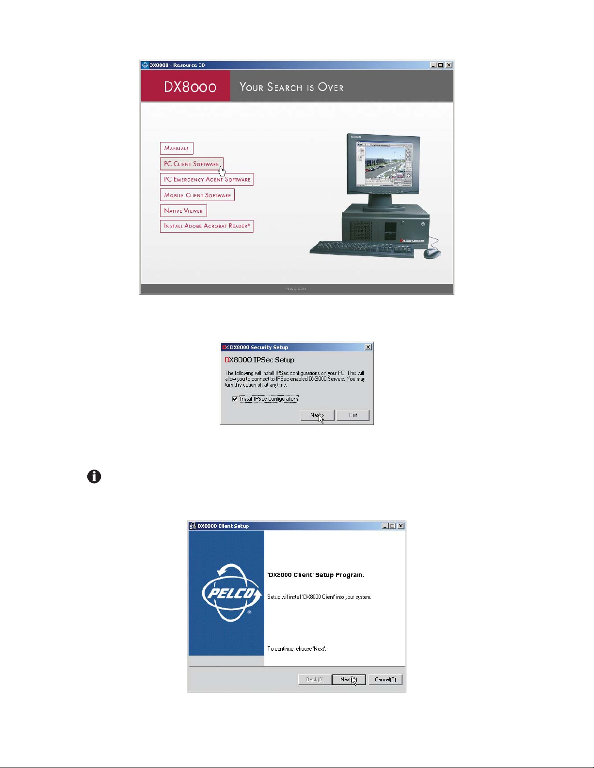
Figure 1. Resource CD Screen: PC Client Installation Option
4. Click “PC Client Software.” The DX8000 Security Setup dialog box opens.
Figure 2. DX8000 Security Setup Dialog Box
5. Verify that the “Install IPSec Configurations” check box is selected.
IMPORTANT: IPSec is a standard security protocol used by the DX8000 Series DVR and its clients to communicate safely over a network.
Although IPSec security can be disabled at any time, it must be enabled in order to communicate with a DX8000 server.
6. Click Next. The DX8000 Client Setup dialog box opens.
Figure 3.
14 C626M-B (3/05)
DX8000 PC Client Application
DX8000 PC Client Setup Dialog Box
Page 15
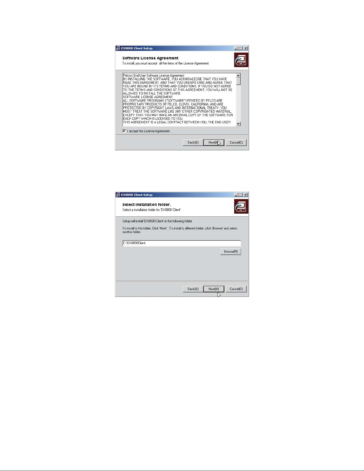
7. Click Next. The Software License Agreement dialog box opens.
Figure 4. PC Client Software License Agreement Dialog Box
8. Read the license agreement and select the “I accept this License Agreement” check box.
9. Click Next. The Select Installation Folder dialog box opens.
Figure 5. PC Client Select Installation Folder Dialog Box
10. Click Next to accept the default installation folder.
C626M-B (3/05) 15
DX8000 PC Client Application
Page 16
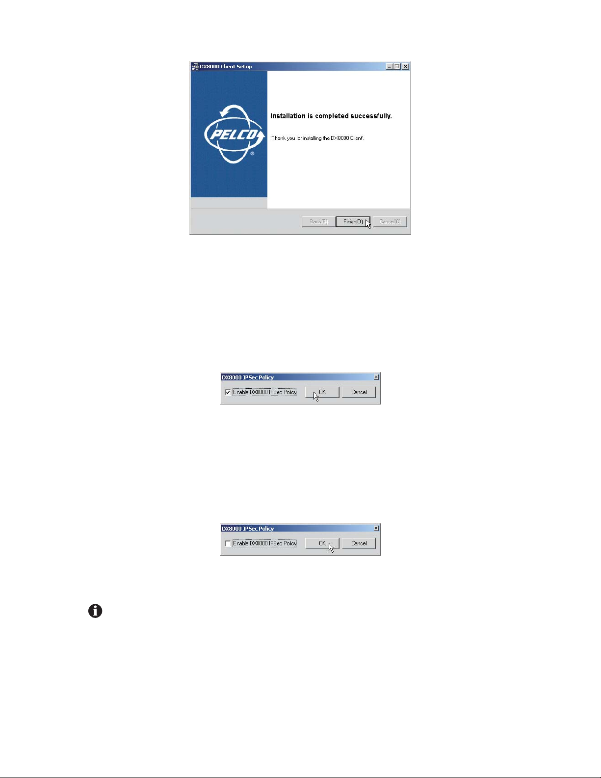
Figure 6. PC Client Installation Finalization Dialog Box
11. Click Finish to complete the installation process.
ENABLING IPSEC SECURITY SERVICES
In order to communicate with a networked DX8000 Series DVR, IPSec security must be enabled on your PC computer.
To enable IPSec security services:
1. Go to Start > Manage IPSec Policy. The DX8000 IPSec Policy dialog box opens.
Figure 7. Enabling IPSec Security for the PC Client Application
2. Select the Enable DX8000 IPSec Policy check box if it is not already selected.
DISABLING IPSEC SECURITY SERVICES
To disable IPSec security services:
1. Go to Start > Manage IPSec Policy. The DX8000 IPSec Policy dialog box opens.
Figure 8. Enabling IPSec Security for the PC Client Application
2. De-select the Enable DX8000 IPSec Policy check box.
IMPORTANT: Disabling IPSec security services may hamper your PC’s ability to communicate with DX8000 servers. Consult your system
administrator before disabling IPSec security.
16 C626M-B (3/05)
DX8000 PC Client Application
Page 17

Before You Begin
Ensure that the following requirements have been met before starting the PC Client application:
1. Make sure there is at least one active DX8000 Series DVR available on your network and your PC computer is set up to access it. Consult
your network administrator for more information.
2. Install the DX8000 PC Client application on your PC computer if you have not done so already. Refer to Installing the PC Client Application
on page 13 for instructions.
3. Make sure you have a valid, active account on the DX8000 DVR server you want to access. Consult your system administrator if you have
not been assigned a DX8000 user name and password.
4. Make sure IPSec security services are installed and enabled on your PC. Refer to Installing the PC Client Application on page 13 and
Enabling IPSec Security Services on page 16 for more information.
C626M-B (3/05) 17
DX8000 PC Client Application
Page 18
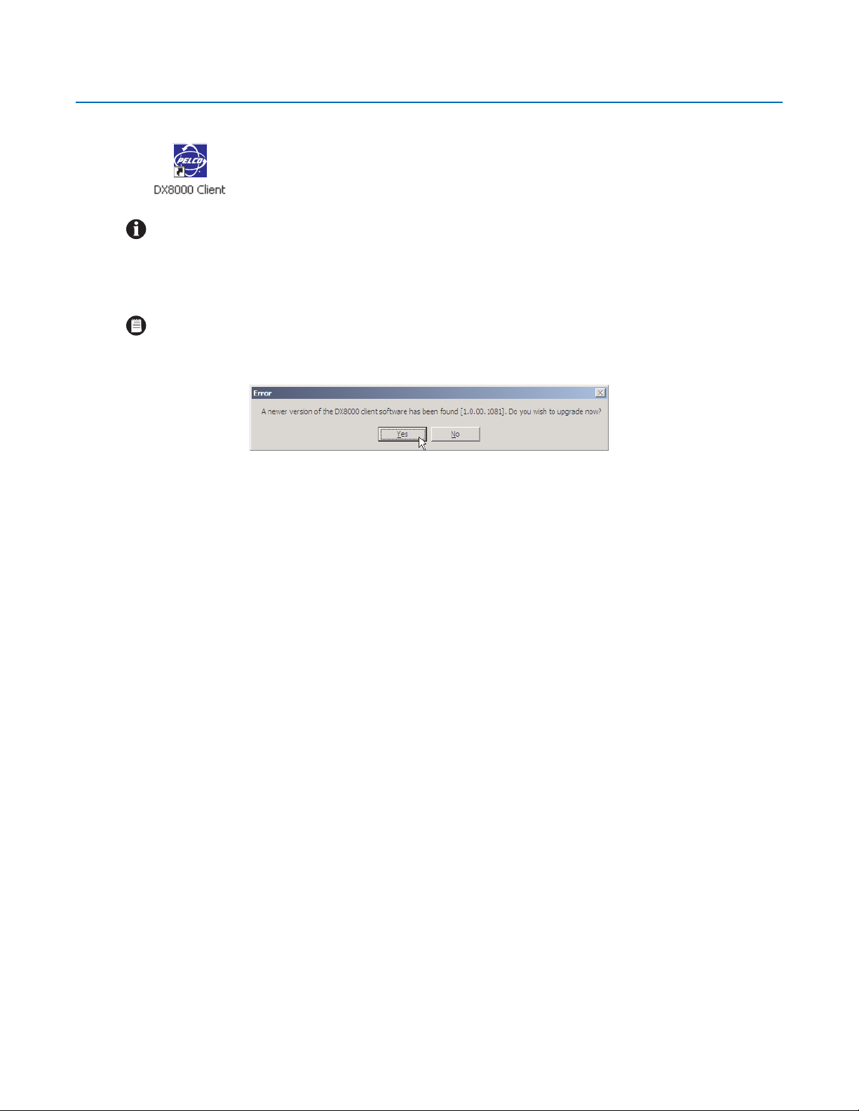
Starting the DX8000 PC Client Application
To start the DX8000 Client Application, double-click the DX8000 Client icon on your desktop.
IMPORTANT: To avoid potential problems and conflicts within your computer’s video subsystem, run only one instance of the PC Client
application at a time.
AUTOMATIC SYSTEM UPGRADE
NOTE: Each time the PC Client application starts, the system will check the network to see if there is a newer version of the software
available for upgrade. If a new version is found, a message screen like the one in Figure 9 will appear. When this screen appears, click Yes
and the DX8000 PC Client software will automatically download the upgrade files, install them, and restart your computer.
Figure 9. Client Upgrade Notice
To check the current version of software, go to Help > About.
18 C626M-B (3/05)
DX8000 PC Client Application
Page 19
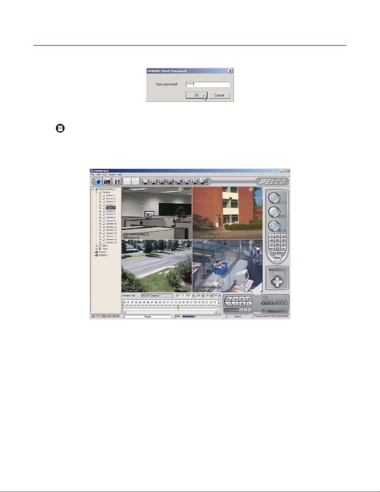
PC Client Application Log-In
To access the DX8000 PC Client application, enter a valid password in the “Input password” text box.
Figure 10. DX8000 Client Password Dialog Box
NOTE: The default password for the DX8000 PC Client application is “000000.” You should change the client password immediately after
logging in to the software for the first time. Follow the instructions below to change the client application log-in password.
To change the DX8000 Client password:
1. Wait while the software loads and the main screen appears.
Figure 11. DX8000 PC Client Application Main Screen
C626M-B (3/05) 19
DX8000 PC Client Application
Page 20
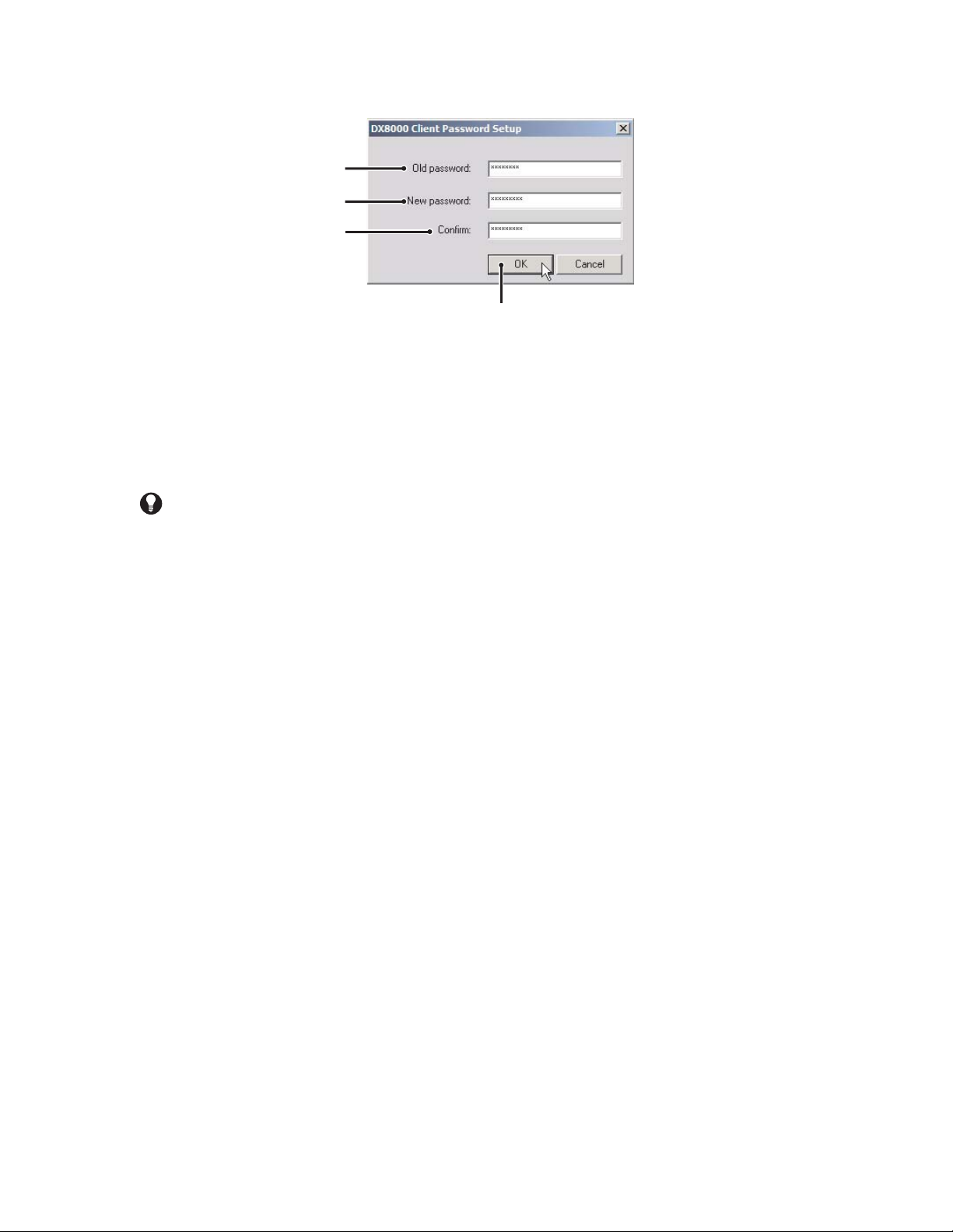
2. Go to File > Client Password. The DX8000 Client Password Setup dialog box opens.
Figure 12. DX8000 Client Password Setup Dialog Box
3. Enter the old password in the “Old password” text box.
4. Enter a new password in the “New password” text box.
5. Re-enter the new password in the “Confirm” text box.
6. Click OK.
TIP: Remember the new client password or write it down and store it in a secure location.
20 C626M-B (3/05)
DX8000 PC Client Application
Page 21
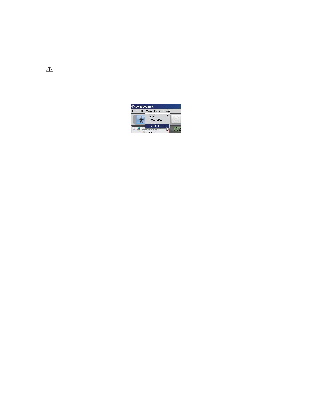
Enabling DirectDraw Video Hardware Acceleration
If your computer’s video hardware supports Microsoft
®
DirectDraw
®
extensions, you can enable DirectDraw to enhance video performance.
Enabling DirectDraw improves performance by delegating graphics acceleration duties to your PC’s video hardware instead of your computer’s
main processor.
WARNING: Do not enable DirectDraw on the PC Client application unless you are certain that your hardware supports DirectDraw hard-
ware acceleration. Check the documentation that came with your PC and your graphics card before enabling DirectDraw. Although some
VGA cards support DirectDraw, not all are compatible with the DX8000 PC Client application. Check the Pelco Web site for a complete list
of compatible VGA cards.
To enable DirectDraw hardware acceleration, go to View > DirectX Draw.
Figure 13.
View Menu DirectDraw Option
C626M-B (3/05) 21
DX8000 PC Client Application
Page 22
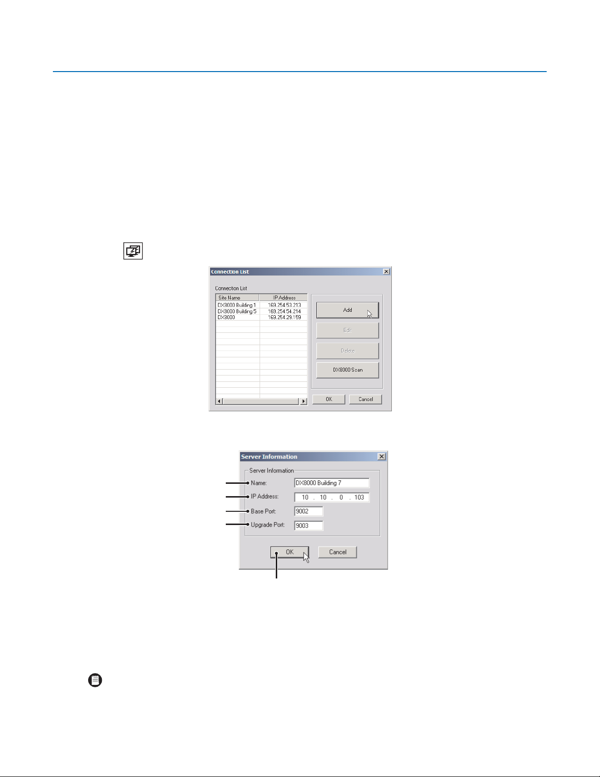
•
Connecting to DX8000 DVR Server Sites
ADDING A DX8000 DVR SERVER TO THE CONNECTION LIST
The DX8000 PC Client application allows operators and DVRs to be geographically dispersed. Up to five DVR servers can be actively viewed from
a single PC client. Up to 50 DX8000 server sites can be added to the Connection List.
The PC Client application facilitates
Remote viewing of live and playback video
Index, thumbnail, and pixel searching
Exporting to a variety of media and formats
Printing still images from video
Limited remote control and administration
To add a site to the Connection List when you know the site’s IP address:
1. Click . The Connection List dialog box opens.
•
•
•
•
Figure 14.
2. Click Add. The Server Information dialog box opens.
Connection List Dialog Box
Figure 15.
3. Enter the name of the DX8000 Series DVR you wish to connect to.
4. Enter the IP address of the DVR.
5. If necessary enter a new base port number (9002 is the default).
NOTE: Consult your network administrator before assigning or changing port numbers. Make sure that the ports are not blocked internally,
but are protected from external threats by a firewall. Client and server ports must be identical.
Server Information Dialog Box
22 C626M-B (3/05)
DX8000 PC Client Application
Page 23
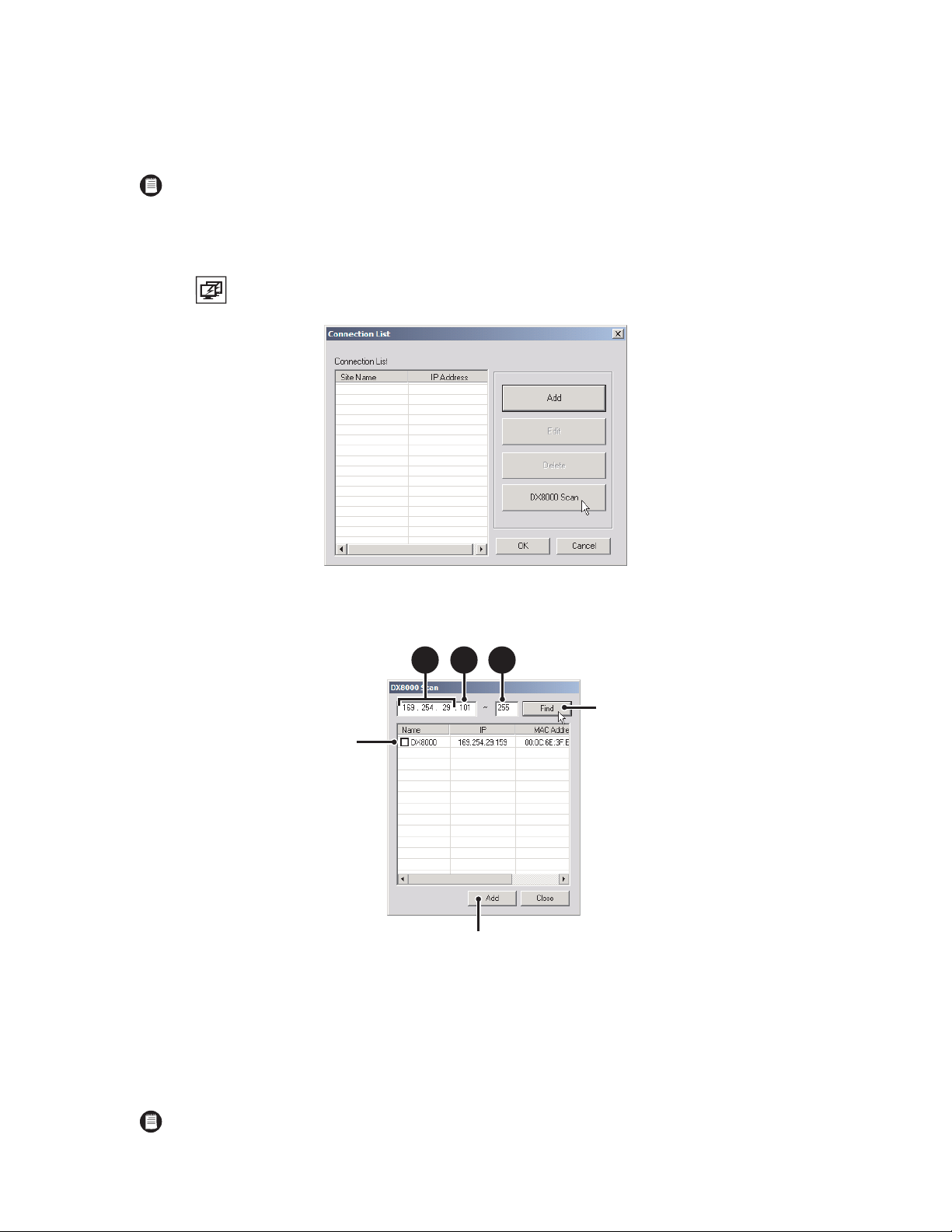
6. If necessary enter a software upgrade port number (9003 is the default).
7. Click OK. The site appears in the Connection List.
To add a remote DVR site to the Connection List when you do not know the IP address of the site:
NOTE: To be successful, the following stipulations must be satisfied:
Each DVR must be attached to the same subnet.
The first three octets of the IP address of the subnet must be known.
The range of addresses used in the last octet of the subnet must be known.
1. Click . The Connection List dialog box opens.
•
•
•
Figure 16. Connection List Dialog Box
2. Click DX8000 Scan. The DX8000 Scan dialog box opens.
3a 3b 3c
Figure 17. DX8000 Scan Dialog Box
3. Enter an IP address range to search for DVR sites.
a. Enter the first three octets of the IP range you wish to search; for example, 10.10.1.
b. Enter the beginning value for the search range in the fourth octet; for example, 001.
c. Enter the final value for the search range in the text box provided; for example, 254.
NOTE: Each octet of the IP address must be an integer between 1 and 255.
C626M-B (3/05) 23
DX8000 PC Client Application
Page 24
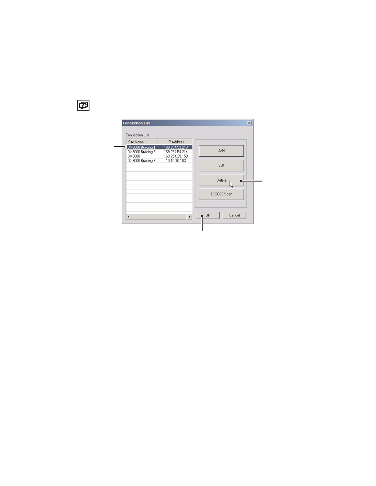
4. Click Find.
5. Select one or more DX8000 servers to add to the site tree.
6. Click Add. The site appears in the Connection List.
7. Click OK when you return to the Connection List dialog box.
DELETING A DX8000 DVR SERVER FROM THE CONNECTION LIST
1. Click . The Connection List dialog box opens.
Figure 18. Deleting a Site from the Connection List
2. Select the DX8000 Series DVR you wish to delete.
3. Click Delete. The site disappears from the Connection List.
4. Click OK.
24 C626M-B (3/05)
DX8000 PC Client Application
Page 25
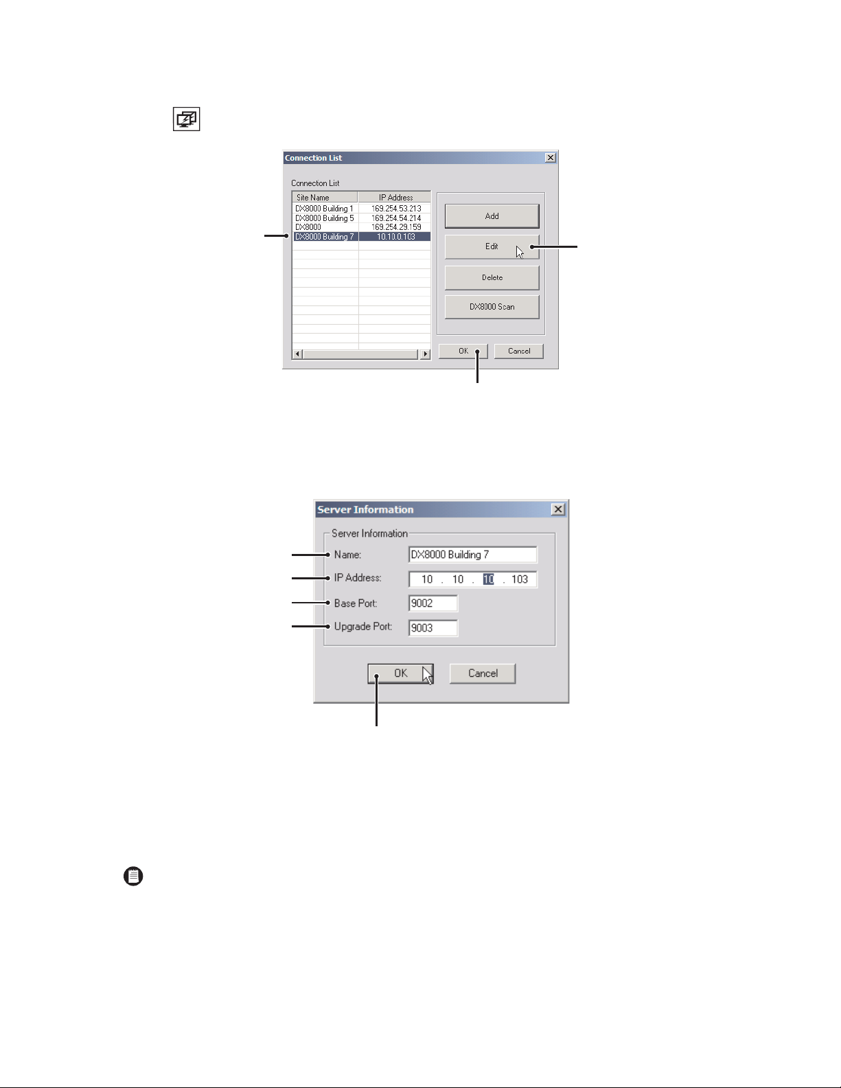
EDITING A DX8000 SERVER’S INFORMATION FROM THE CONNECTION LIST
1. Click . The Connection List dialog box opens.
Figure 19. Editing a Site from the Connection List
2. Select the DX8000 Series DVR you wish to edit.
3. Click Edit. The Server Information dialog box opens.
Figure 20. Editing Server Information
4. Enter a new name for the server.
5. Enter a new IP address for the server.
6. If necessary enter a new base port number (9002 is the default).
NOTE: Consult your network administrator before assigning or changing port numbers. Make sure that the ports are not blocked internally,
but are protected from external threats by a firewall. Client and server ports must be identical.
7. If necessary enter a software upgrade port number (9003 is the default).
8. Click OK. The site appears in the Connection List.
9. Click OK when you return to the Connection List dialog box.
C626M-B (3/05) 25
DX8000 PC Client Application
Page 26
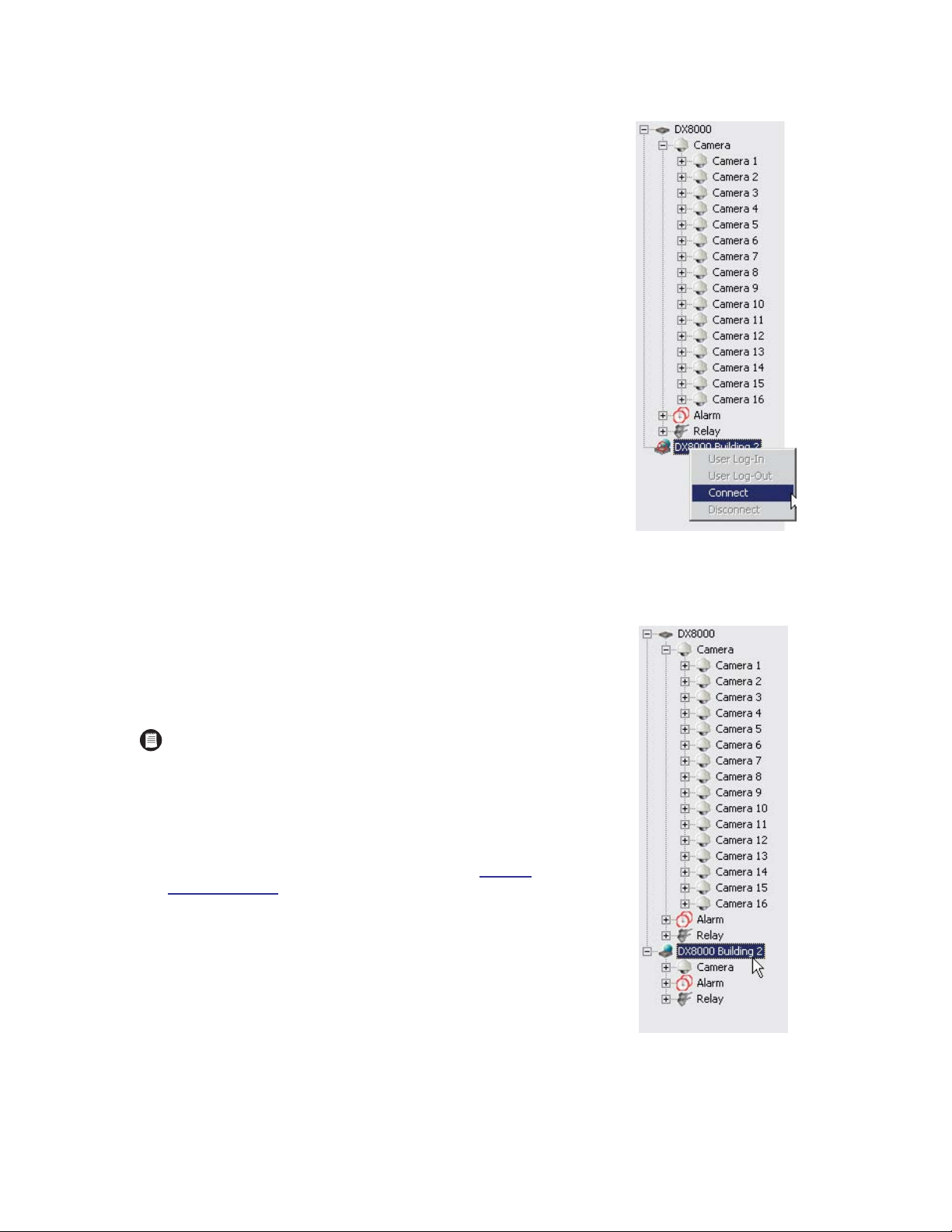
CONNECTING TO A REMOTE SITE
You can view live and playback video from multiple DX8000 DVR servers
simultaneously.
To connect to an active DX8000 server on the network:
1. Right-click the remote site name from the site tree.
2. Select Connect from the quick-menu.
LOGGING IN TO A REMOTE SITE
After a connection to a remote site has been established, log in with a valid user
name and password for that site.
To log in to a remote site:
1. Select a remote DX8000 Series DVR site from the site tree.
NOTE: To access the features of the DX8000 Series DVR, you must log
in with a valid user name and password. The DX8000 comes equipped
with a built-in user account named “Guest.” Each time the unit is turned
on, the Guest account is automatically activated. In addition to the
Guest account, there are four other user access levels, or groups, that
can be configured on the DX8000. The Guest user is granted only limited
access to the system. The other four access levels range from the
Administrator group, with the most rights and privileges, to the
Restricted group, with the least rights and privileges. Refer to Defi
of User Access Levels
permissions of the user group to which you have been assigned. To
operate and configure all but the most basic features of the DX8000, you
must be assigned a user account other than Guest. If you have not been
assigned a user account, contact your system administrator before
proceeding.
on page 131 for information on the rights and
Figure 21. Remote Site Connect Quick-Menu
nition
Figure 22. Selecting a Site
26 C626M-B (3/05)
DX8000 PC Client Application
Page 27
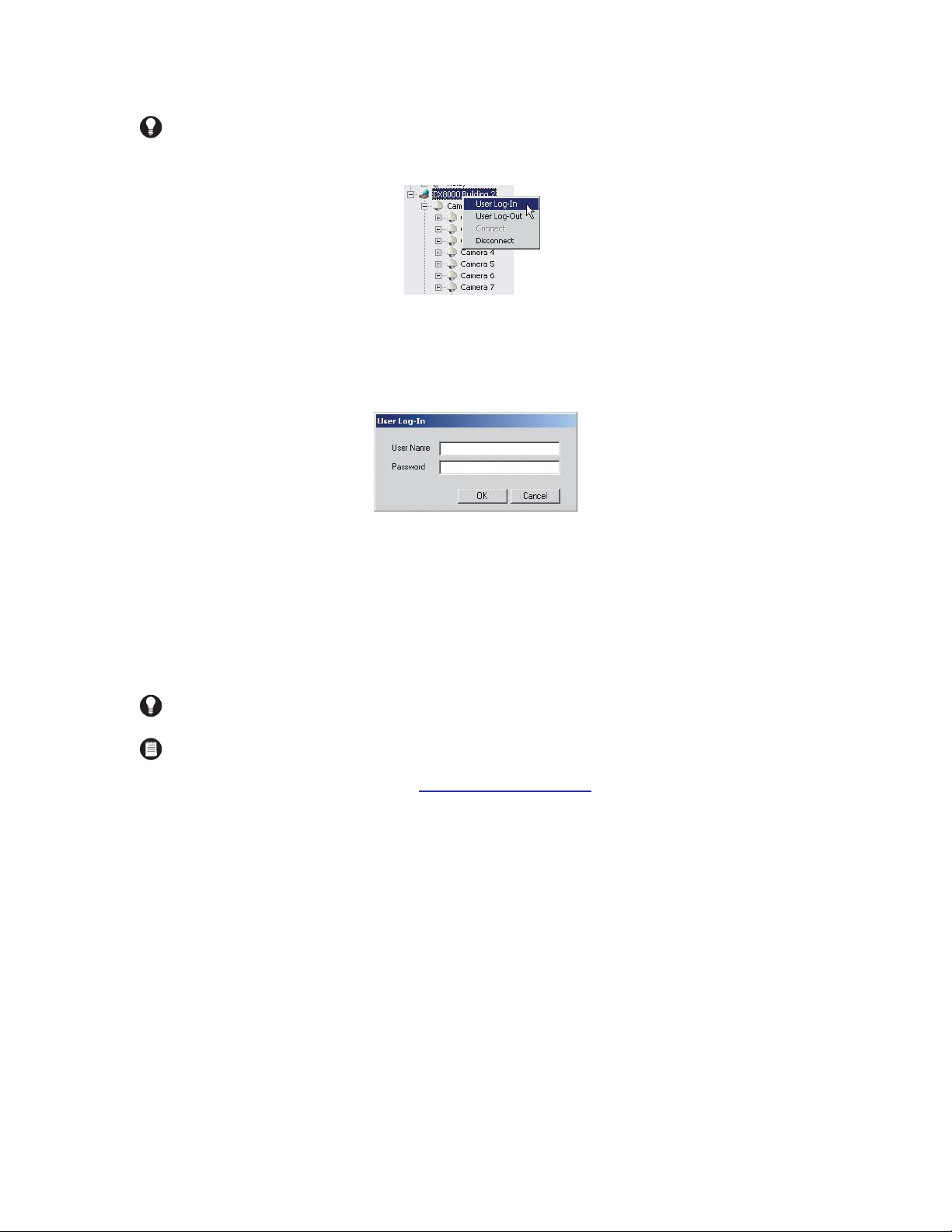
2. Go to File > User Log-in.
TIP: You can also log in to a remote site by right-clicking its site name and then selecting User Log-In from the quick-menu. Refer to
Figure 23.
Figure 23. Log-in Quick-Menu
3. Enter a valid user name in the User Name field and a valid password in the Password field.
4. Click OK.
•
•
LOGGING OUT OF A REMOTE SITE
To log out of a remote DVR site:
1. Select the remote server from the site tree.
2. Go to File > User Log-Out.
TIP: You can also log out of a remote DVR by right-clicking its site name from the site tree and selecting User Log-Out from the quick-
menu.
NOTES:
Logging out of a remote DVR does not disconnect you from that system. Logging out will return you to the Guest account.
To disconnect from a remote server, refer to Disconnecting from a Remote Site on page 28 .
You can only log out of one server at a time. If you are logged into multiple servers you must log out of each server individually.
Figure 24. Log-in Dialog Box
C626M-B (3/05) 27
DX8000 PC Client Application
Page 28
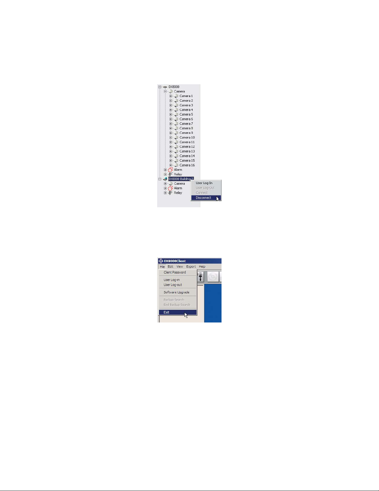
DISCONNECTING FROM A REMOTE SITE
To terminate a connection with a remote DX8000 server:
1. Right-click the name of the remote site from the site tree.
2. Select Disconnect from the quick-menu.
Figure 25. Remote Site Disconnect Quick-Menu
EXITING THE DX8000 PC CLIENT APPLICATION
To exit the DX8000 PC Client application and return to the Windows operating system, go to File > Exit.
Figure 26. Exiting the PC Client Application
28 C626M-B (3/05)
DX8000 PC Client Application
Page 29

Description of Operating Modes
The DX8000 Series DVR has four primary operating modes. These are Live, Playback, Search, and Setup modes. Each operating mode is accessed
by clicking its corresponding button on the toolbar.
Live Mode – Allows all users to view live video.
Playback Mode – Allows users with Standard User access and higher to play back recorded video.
Search Mode – Allows users with Standard User access and higher to search video data using specific criteria.
Setup Mode – Allows users with Power User access and higher to set up the features and options for the DVR.
C626M-B (3/05) 29DX8000 PC Client Application
Page 30
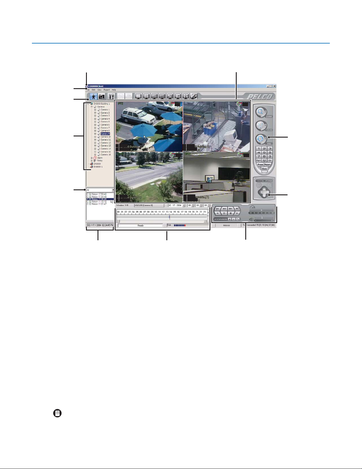
DX8000 PC Client Application Main Screen
The main screen provides access to both live and recorded video.
S1 DX8000
C1 Camera 1
S1 DX8000
C3 Camera 3
REC
S1 DX8000
C2 Camera 2
REC REC
S1 DX8000
C4 Camera 4
REC
Figure 27. Main Screen Layout
Title Bar: Displays the DX8000 application title.
Menu Bar: Provides access to drop-down menus.
Toolbar: Provides access to display, setup, export, and search tools.
Site Tree: Displays top-down, hierarchical management of DX8000 resources, such as servers, cameras, alarms, and relays.
View Panels: Display live and playback video from attached cameras.
PTZ Control Panel: Allows users with access rights to operate camera lens control features and to program PTZ presets, patterns, and
tours.
Event Index Panel: Allows users with access rights to search motion and alarm events within a 24-hour period specified in the playback
timeline.
Playback Timeline: Displays a 24-hour timeline marked with color-coded video events. Allows users with Standard User access rights to
select a date and time for playback.
Playback Control Panel: Provides buttons for users with access rights to control video playback. Includes forward and reverse playback
and still image. It also provides controls for playback speed and volume.
Playback Zoom Control: Provides users with access rights to operate digital zoom features during playback.
Status Bar: Displays current date and time, recorder processing status, disk status indicator, user name of currently logged-in user, and total
amount of recorded video.
NOTE: As the storage array of the DX8000 fills beyond its capacity, video is deleted in a first-in, first-out (FIFO) fashion. The disk status
indicator on the status bar shows the amount of disk space used by recorded video. The red indicator marks the current recording position
of the disk array, blue indicators mark parts of the array that are storing previously recorded video, and clear indicates that no video has
been recorded in that area of the array.
30 C626M-B (3/05)DX8000 PC Client Application
Page 31

WORKING WITH THE SITE TREE
The site tree provides access to DX8000 resources, such as cameras, alarm inputs, and relay outputs. Objects can be selected by clicking once
with the left mouse button and linked by dragging and dropping with the mouse.
SITE NAME
CAMERA NAME
CHANNEL INFORMATION
-RECORDING TYPE
-RESOLUTION
-FRAME RATE
-IMAGE QUALITY
ALARM INPUTS
RELAY OUTPUTS
Figure 28. Site Tree
NOTE: Site tree information reflects the current server configuration.
C626M-B (3/05) 31DX8000 PC Client Application
Page 32

ASSIGNING CAMERAS TO VIEW PANELS
The DX8000 includes 32 view panels that can display cameras from up to five connected DVR sites.
To assign a single camera to a view panel:
1. Click .
2. In the site tree, click the plus sign (+) next to to expand the tree if necessary.
3. Drag the camera from the site tree onto a view panel.
TIP: To assign all cameras from a single site to the view panels at once, drag onto a single view panel. (The default arrangement of
cameras is Camera1, Camera2, Camera3 – from left to right, top to bottom.)
4. Repeat the process in step 3 for up to 32 cameras from up to five DVR sites.
NOTE: The DX8000 Series DVR supports triplex operation. Triplex operation means the DX8000 will continuously record even while users
view simultaneous live and playback video or modify the system setup.
Figure 29. Dragging a Camera to a View Panel
32 C626M-B (3/05)DX8000 PC Client Application
Page 33

LINKING ALARM INPUTS AND RELAY OUTPUTS TO CAMERAS
To link an alarm input to a camera:
1. Click .
2. In the site tree, click the plus sign (+) next to the camera to which you want to link alarms.
Figure 30. Expanding a Camera Channel Branch 1
3. Click the plus sign (+) next to the to see the list of alarm inputs.
4. Drag an alarm input onto a camera.
Figure 31. Dragging an Alarm Input to a Camera
C626M-B (3/05) 33DX8000 PC Client Application
Page 34

To link a relay output to a camera:
1. Click .
2. In the site tree, click the plus sign (+) next to the camera to which you want to link relays.
Figure 32. Expanding a Camera Channel Branch 2
3. Click the plus sign (+) next to to see the list of relay outputs.
34 C626M-B (3/05)DX8000 PC Client Application
Figure 33. Expanding a Relay Branch
Page 35

4. Drag a relay onto a camera.
Figure 34. Dragging a Relay to a Camera
TIP: You can link multiple alarms and relays to a single camera. You can also link a single alarm or relay to multiple cameras. You can also
link alarms and relays to cameras by dragging them onto individual camera view panels.
C626M-B (3/05) 35DX8000 PC Client Application
Page 36

LINKING RELAY OUTPUTS TO ALARM INPUTS
To link a relay output to an alarm:
1. Click .
2. In the site tree, click the plus sign (+) next to to expand the alarm tree if needed.
Figure 35. Expanding an Alarm Input Branch
3. Click the plus sign (+) next to to expand the relay tree if needed.
4. Drag a relay output onto an alarm input.
TIP: Relays can also be linked to cameras and alarms on the relay and alarm settings page. Refer to Configuring Basic Relay and Alarm
Settings on page 102 for more information.
36 C626M-B (3/05)DX8000 PC Client Application
Figure 36. Dragging a Relay Output to an Alarm Input
Page 37

REMOVING A LINKED ALARM INPUT FROM A CAMERA
To unlink an alarm from a camera:
1. Click .
2. In the site tree, click the plus sign (+) next to the camera from which you want to remove alarms or relays.
3. Drag the alarm or relay above or below the site tree panel and release the mouse button.
4. Repeat the above process for each alarm or relay you want to remove.
Figure 37. Removing an Alarm Input from a Camera
C626M-B (3/05) 37DX8000 PC Client Application
Page 38

REMOVING A LINKED RELAY OUTPUT FROM A CAMERA
To unlink a relay from a camera:
1. Click .
2. In the site tree, click the plus sign (+) next to the camera from which you want to remove the relay output.
3. Drag the relay above or below the site tree panel and release the mouse button.
4. Repeat the above process for each relay you want to remove.
38 C626M-B (3/05)DX8000 PC Client Application
Figure 38. Removing a Relay Output from a Camera
Page 39

REMOVING A LINKED RELAY OUTPUT FROM AN ALARM INPUT
To unlink a relay from an alarm:
1. Click .
2. In the site tree, click the plus sign (+) next to the alarm input from which you want to remove the relay output.
3. Drag the relay either above or below the site tree panel and release the mouse button.
4. Repeat the above process for each relay you want to remove.
Figure 39. Removing a Relay Output from an Alarm Input
C626M-B (3/05) 39DX8000 PC Client Application
Page 40

UNDERSTANDING VIEW PANELS AND WINDOWS
View Panels – A view panel is a division of a view window. Each view panel contains only a single camera channel. Up to sixteen view panels
can fit in a single view window.
View Windows – A view window is made up of the entire camera viewing area. View windows are divided into multiple panels. Each window
can display from one to sixteen individual cameras.
VIEW PANELS
WINDOWS
Figure 40. View Panels and Window
40 C626M-B (3/05)DX8000 PC Client Application
Page 41

CONFIGURING VIEW PANELS
The DX8000 PC Client Application can display up to sixteen cameras simultaneously on a single window.
To configure the view panels in a window:
1. Click .
Figure 41. Main Display
2. Select a view panel division button from the toolbar.
Displays one camera. Divides screen into 1+5, 2+8, or 1+12 view panels.
Displays four cameras at a time (quad display).
Displays nine cameras at a time.
Displays 16 cameras at a time.
Turns window cycling on and off. (Cycles through each
view window ensuring all cameras get displayed.)
Full-screen view. Expands view window to occupy entire
monitor screen. Click the right mouse button to exit fullscreen view.
C626M-B (3/05) 41DX8000 PC Client Application
Page 42

NAVIGATING BETWEEN VIEW WINDOWS
The DX8000 PC Client application allows you to monitor up to 32 channels; however, the main screen can display only one to sixteen view panels
at a time. Since only one screen window can be viewed at a time, you must cycle through multiple windows to view any hidden windows.
For example, if a single channel is selected to cover the entire window, there will be an additional 31 hidden windows available to cycle through.
Similarly, if four channels are displayed on a single window, there will be seven hidden windows and so on.
Pressing one of the view panel division buttons sets the number of visible channels on a screen window. Figure 42 illustrates the view panel
division buttons available on the toolbar.
TOTAL # OF WINDOWSCURRENT WINDOW
Figure 42. View Window Identifier
To manually cycle through hidden view windows, click one of the screen division buttons repeatedly.
For example, click repeatedly to cycle through each of the eight available view windows.
Continue clicking until you return to window one.
To cycle automatically through view windows, click .
To turn window cycling off, click again.
29 30
25 26
21 22
27
17 18
23
13 14
9
15
5
6
11 12
1
32
12
7
4
3
8
20
19
10
16
13 - 16
9 - 12
5 - 8
1 - 4
1
31
28
24
17 - 20
32
26 - 28
21 - 24
29 - 32
17 18 19
8 9 10
20 21 22
1 2 3
11 12 13
23 24 25
4 5 6
14 15 16
7 8 9
25 26 27
28 29 30
32 31 32
8 - 16
1 - 9
25 - 32
17 - 25
18
17
1
2
3
22
21
5
6
7
25
26
9
10
11
29
303231
15
13
14
Figure 43. Hidden View Windows
TIP: Double-click a view panel to expand it so it fills the entire view window. Double-click again to return to the previous view.
19
20
4
23
24
8
27
28
12
17 - 32
16
1 - 16
42 C626M-B (3/05)DX8000 PC Client Application
Page 43

Live View Mode
All users can view live video from the main screen. Users with Standard User access and higher can operate the on-screen PTZ controls.
Click to view live video on the main screen.
ASSIGNING CAMERAS TO VIEW PANELS
1. Drag a camera from the site tree onto a camera view panel. Refer to Assigning Cameras to View Panels on page 32 for instructions on how
to assign cameras to view panels.
2. Repeat the process in step 1 for up to 32 cameras from up to five different DX8000 sites.
Figure 44. Dragging a Camera to a View Panel
C626M-B (3/05) 43DX8000 PC Client Application
Page 44

LIVE VIEW ON-SCREEN DISPLAY (OSD)
The DX8000 PC Client Application’s OSD consists of camera and site information that is superimposed on each view panel. Each display item in
the OSD can be customized for both live and playback viewing.
Figure 45. Live View OSD
PTZ: Indicates that PTZ control is enabled.
: Indicates that audio recording is enabled.
REC: Indicates camera recording mode and status.
• Green indicates normal recording.
• Blue indicates motion recording.
• Red indicates alarm recording.
• Yellow indicates event recording.
NOTE: A blinking REC indicator signifies event recording.
Site Designator: Lists the number and name of the current site.
Camera Designator: Lists the number and name of the current camera.
On-Screen PTZ Control: Facilitates mouse control of PTZ functions. Refer to Operating the On-Screen Pan, Tilt, and Zoom (PTZ) Controls
on page 47.
Instant Recording: Starts/stops instant recording if enabled.
44 C626M-B (3/05)DX8000 PC Client Application
Page 45

CUSTOMIZING THE ON-SCREEN DISPLAY (OSD)
Users with Power User access and higher can add and delete on-screen display items.
To customize the on-screen display:
1. Go to View > OSD and then select the items you want to add to or delete from the OSD. Items include
• Site Name
• Camera Name
• Video Recording
• Audio Recording
• PTZ
• Instant Recording
• Select All (shows all items on screen)
Figure 46. OSD Menu Options
2. Go to View > OSD > Background Color > Set Color to add a contrasting background field behind each OSD display item.
or
Go to View > OSD > Background Color > Disable Background to remove background field.
INSTANT RECORDING
ENABLING AND DISABLING
Users with Power User access and higher can configure the DX8000 for recording video both instantly and in accordance with a preset schedule.
The Instant Recording mode is enabled from the schedule setup screen. Instant recording is activated from the main screen by clicking the
Instant Recording icon. For information about adding the Instant Recording icon to the OSD, refer to Adding Instant Recording to OSD on page 46.
To enable the Instant Recording mode:
1. Click .
2. Click .
3. In the Camera Settings Panel, from the Instant Recording drop-down box, select Enable.
Figure 47. Enabling Instant Recording
To disable the Instant Recording mode, select Disable from the Instant Recording drop-down box.
C626M-B (3/05) 45DX8000 PC Client Application
Page 46

ADDING INSTANT RECORDING TO OSD
To add the Instant Recording icon to the OSD, click View > OSD > Instant Recording.
Figure 48. Adding the Instant Recording to OSD
ACTIVATING AND DEACTIVATING INSTANT RECORDING
The Instant Recording mode must first be enabled from the Schedule setup screen. For more information, refer to Instant Recording on page 45.
To activate instant recording:
1. Ensure that instant recording is enabled, and then double-click the Instant Recording icon. The Instant Recording icon changes from silver
to blue, indicating that instant recording is activated.
2. If video recording is enabled, verify that REC blinks, If video recording is not enabled, REC is not displayed.
To deactivate instant recording, double-click the Instant Recording icon.
46 C626M-B (3/05)DX8000 PC Client Application
Figure 49. Activating Instant Recording
Page 47

OPERATING THE ON-SCREEN PAN, TILT, AND ZOOM (PTZ) CONTROLS
Users with Standard User access and higher may operate pan, tilt, and lens functions of cameras that support such features. PTZ functions can
be controlled on-screen in Live mode using the mouse.
NOTE: PTZ control is available only for cameras that support PTZ functions using Pelco’s P, D, or Coaxitron® protocols. Refer to RS-422/
RS-485 Communication Port Software Configuration section in the Operation and Programming manual for information on configuring PTZ
ports. In addition, the PTZ option must be enabled and a protocol must be assigned to the camera channel. Refer to Configuring Cameras on
page 97 for instructions.
To operate the on-screen PTZ controls:
1. Click .
2. Select a PTZ-enabled camera from the site tree.
3. Place the mouse pointer in the middle of the camera’s view panel. The mouse pointer will change to a black cross when on-screen PTZ
control is available.
Figure 50. On-Screen PTZ
4. Click the left mouse button, and then drag the mouse pointer in the direction you want to move the camera. The display changes to an
arrow indicating the direction of the mouse.
Figure 51. On-Screen PTZ Movement
5. Release the mouse button when you have repositioned the camera to the desired location.
C626M-B (3/05) 47DX8000 PC Client Application
Page 48

6. To adjust camera lens features, click the plus (+) or minus (−) button next to each function on the keypad. Refer to Figure 52.
Figure 52. PTZ Keypad with Camera Lens Controls
7. To adjust camera zoom using the mouse, rotate the mouse wheel forward to zoom in and backward to zoom out.
Figure 53. Mouse Wheel Zoom
TIP: You can also use keyboard shortcuts to operate the lens features of cameras such as Pelco’s Spectra III™. For more information about
using keyboard shortcuts, refer to Using PC Keyboard Shortcuts to Operate PTZ and Lens Functions on page 49.
48 C626M-B (3/05)DX8000 PC Client Application
Page 49

USING PC KEYBOARD SHORTCUTS TO OPERATE PTZ AND LENS FUNCTIONS
Users with Standard User access and higher may use a PC keyboard to operate PTZ and lens functions of cameras that support such features.
PTZ and lens functions can be controlled in Live mode using the keyboard.
Table A describes the keyboard buttons that you use to control PTZ and lens functions. Operation of the keyboard shortcuts, with the exception of
the plus (+) and minus (−) keys, are self-explanatory. A procedure is provided following Table A that describes how to use the plus (+) and minus
(−) keys.
Table A. Standard PC Keyboard Functions for Controlling PTZ and Lens Functions
Key(s) Description
Insert and Delete These keys provide the following functionality:
• On-screen display, preset and pattern modes: Insert increases and Delete decreases focus,
performing the same actions as the focus control on the PTZ keypad.
• Remote camera programming mode: Insert and Delete perform the same actions as the PTZ
keypad focus (+) and (−) buttons, navigating up and down the camera menu choices.
Home and End These keys provide the following functionality:
• On-screen display, preset and pattern modes: The Home key opens and the End key closes
the iris, performing the same actions as the PTZ keypad iris (+) and (−) buttons.
• Remote camera programming mode: The Home key selects an option from the camera’s on-
screen menu. The End key cancels an option or exit a menu. These keys perform the same
actions as the PTZ keypad iris (+) and (−) buttons.
Page Up and Page Down These keys perform the same functionality in the on-screen display and the preset and pattern
modes as the PTZ keypad zoom (+) and (−) buttons. Page Up zooms in; Page Down zooms out.
Up and Down Arrow These keys provide the following functionality:
• On-screen display, preset and pattern modes: The up arrow key raises the camera and the
down arrow key lowers the camera. The keys perform the same actions as clicking the left
mouse button when in on-screen PTZ control and dragging the mouse pointer up and down.
• Remote camera programming mode: The arrow keys navigate up and down the camera menu
choices. The keys perform the same actions as the PTZ keypad focus (+) and (−) buttons.
Left and Right Arrow These keys provide the same actions as clicking the left mouse button for on-screen PTZ control
and dragging the mouse pointer left and right. The left arrow key pans the camera in a counterclockwise direction, and the right arrow key pans the camera in a clockwise direction.
+ and – These keys perform similar actions in the on-screen display and the preset and pattern modes as
clicking the left mouse button when in on-screen PTZ control and dragging the mouse pointer to
change the speed of camera movement. The plus (+) key, pressed once increases the camera’s pan
and tilt speed. The minus (−) key pressed once decreases the camera’s pan and tilt speed. Each
time the plus (+) key is pressed the pan and tilt speed is increased toward the maximum speed.
Each time the minus (−) key is pressed, the pan and tilt speed is decreased toward the minimum
speed.
To use the keyboard (+) and (−) keys to control camera pan and tilt speed:
1. Click .
2. Select a PTZ-enabled camera from the site tree.
3. Click the mouse pointer in the camera’s view panel.
4. Press and hold the up/down and left/right arrows to pan and tilt the camera.
5. Press the plus (+) key once to increase the pan and tilt speed. Press the minus (−) key once to decrease the pan and tilt speed.
C626M-B (3/05) 49DX8000 PC Client Application
Page 50

PTZ PRESETS
A preset is a user-defined camera position using pan and tilt, zoom, and focus commands. A DX8000 Series DVR can address up to 32 PTZ
presets (1-32). Preset 95 is reserved for remote camera setup, and preset 99 is reserved for camera autoscan mode.
NOTE: Only cameras that support positioning and programming using D, P, or Coaxitron protocols can use this feature.
IMPORTANT: To program or clear presets, preset tours, and patterns, the icon must be engaged. To activate presets, tours, and
patterns, the icon must be disengaged.
PROGRAMMING A PRESET
TIP: Clicking the icon places DX8000 in PTZ programming mode. While in PTZ programming mode, multiple presets
can be programmed until the icon is pressed again.
To program a PTZ preset:
1. Click .
2. Drag a camera from the site tree onto a view panel.
3. Click .
50 C626M-B (3/05)DX8000 PC Client Application
Figure 54. Main Display with PTZ Control Pad Visible
Page 51

4. Using the on-screen PTZ controls and PTZ keypad, move the camera to the desired position and adjust zoom and iris settings.
EXIT
Figure 55. Moving to a Preset
5. Using the PTZ keypad, select a number for the new preset (for example, 1).
Figure 56. Programming a Preset
6. Click to store the preset in the selected memory location.
7. Repeat steps 4-6 for each preset you want to program.
8. Click again to exit programming mode.
C626M-B (3/05) 51DX8000 PC Client Application
Page 52

ACTIVATING A PRESET
To activate a preset:
1. Click a preset number (1-32) on the keypad.
2. Click to activate preset. The camera repositions to the new preset.
Figure 57. Activating a Preset
TIP: Double-digit presets can be set or activated by pressing the first digit and then the second digit sequentially. For example, preset 20
can be selected by clicking the number 2 and then the number 0 on the PTZ keypad.
CLEARING A PRESET
To clear a preset:
1. Click to enter programming mode.
2. Click the number of the preset you want to clear from the PTZ keypad.
3. Click .
4. Repeat steps 2 and 3 to clear multiple presets.
5. Click to exit programming mode.
Figure 58. Clearing a Preset
52 C626M-B (3/05)DX8000 PC Client Application
Page 53

PTZ PATTERNS
A pattern is a user-defined, viewable camera path with a definite beginning and end. Patterns are made up of a sequence of standard pan, tilt,
and lens commands. Patterns are stored in the internal memory of the PTZ device, such as a Spectra dome, that is connected to the DX8000.
Depending on the type and configuration of the PTZ device, the DX8000 can address up to four unique PTZ patterns. Once defined, a pattern can
be activated with a series of on-screen commands. A pattern will run continuously until it is deactivated.
NOTE: Only PTZ-enabled cameras that support pattern programming through D, P, or Coaxitron protocols can use this feature.
PROGRAMMING A PATTERN
To program a pattern:
1. Click .
2. Drag a camera from the site tree onto a view panel.
3. Click to enter programming mode.
4. Using the PTZ keypad, select a number for the pattern (1 to 4).
5. Click .
6. Move the camera through a series of movements using the on-screen pan and tilt, zoom, and focus controls.
NOTE: Certain PTZ devices, like Pelco’s Spectra series domes, will display an on-screen message stating the amount of remaining memory
available for pattern programming.
Figure 59. Programming a Pattern
To stop programming a pattern:
1. Click .
2. Click .
C626M-B (3/05) 53DX8000 PC Client Application
Page 54

ACTIVATING A PATTERN
To activate a pattern:
1. Click a pattern number (1 to 4) on the keypad.
2. Click .
Figure 60. Activating a Pattern
IMPORTANT: A pattern will repeat indefinitely until it is cleared, another pattern is set, or the on-screen PTZ control is moved.
CLEARING A PATTERN
To clear a pattern:
1. Click to enter programming mode.
2. Select a pattern number (1 to 4) on the keypad.
3. Click .
4. Click .
5. Click again.
6. Click again to exit programming mode.
54 C626M-B (3/05)DX8000 PC Client Application
Figure 61. Clearing a Pattern
Page 55

ACCESSING PROGRAMMING FEATURES OF REMOTE CAMERAS
You can use the PTZ function to program features of remote cameras, such as Pelco’s Spectra or Esprit®.
NOTE: Only cameras that support remote programming through D, P, or Coaxitron protocols can use this feature.
To access a programming menu for a remote camera:
1. Click .
2. Drag a camera from the site tree onto a view panel.
Figure 62. View Panel
C626M-B (3/05) 55DX8000 PC Client Application
Page 56

3. Click from the keypad to access remote camera setup mode.
Figure 63. PTZ Control Panel
TIP: For certain camera models, you can also select preset number 95 from the keypad to access remote setup mode.
To access preset number 95, click , 9, 5, and from the PTZ keypad.
4. Use the on-screen PTZ controls or the focus (+) and focus (−) buttons to navigate up and down camera menu choices.
5. Click the iris (+) button to select an option from the camera’s on-screen menu.
6. Click the iris (−) button to cancel an option or exit a menu.
Figure 64. Camera Setup Menu
TIP: You can also use the on-screen PTZ controls with your mouse to navigate camera menus. Click and drag the mouse up or down to
move between menu options and then select the option using the iris (+) button.
56 C626M-B (3/05)DX8000 PC Client Application
Page 57

SENDING AUXILIARY COMMANDS TO A DEVICE
The DX8000 auxiliary feature allows you to control external equipment connected to the auxiliary outputs of Spectra domes or Esprit positioning
systems. The auxiliary function is implemented through the D Protocol and P Protocol. In this case, the attached camera and DX8000 must be
configured to communicate using one of these protocols.
The Aux key selects the auxiliary mode. Buttons 1- 4 select which of the camera’s auxiliary outputs to operate. Buttons 1–4 operate as a toggle
(on/off) each time they are clicked.
For example, an Esprit equipped with a wiper uses Aux 1 to control the wiper. In this case, pressing Aux+1 sends a command to the Esprit to
operate the wiper. You must configure the camera to establish how the camera responds to an auxiliary command. For detailed information about
how a specific Spectra or Exprit camera system interprets auxiliary commands, refer to the documentation that accompanies your Spectra or
Esprit camera system.
To send an auxiliary command:
1. Click to enter the programming mode.
2. Select the camera in the DX8000 view panel to which you want to send the auxiliary command.
3. Click the Aux button.
Figure 65. Auxiliary (Aux) Button
Keypad buttons 1–4 are available.
Figure 66. Keypad Buttons 1–4
4. Click a keypad button (1–4). The auxiliary function assigned by camera for the selected button is executed.
C626M-B (3/05) 57DX8000 PC Client Application
Page 58

CONFIGURING PRESET TOURS
A preset tour allows a camera to move through a programmed sequence of PTZ presets. The DX8000 Series DVR can store up to four preset
tours. While four tours can be programmed, only one tour can be activated at a time. A preset tour will operate continuously until another PTZ
control action is performed.
NOTE: At least one PTZ preset must be set in order to create a preset tour.
PROGRAMMING PRESET TOURS
To access the Preset tour group programming screen:
1. Click .
2. Click and then on the PTZ keypad to bring up the preset tour dialog box.
Figure 67. Preset Tour Dialog Box
3. Select the preset tour (1-4) that you want to program from the drop-down box.
4. Follow the directions in the following sections to add presets to and delete presets from a tour.
58 C626M-B (3/05)DX8000 PC Client Application
Page 59

Adding Presets to a Tour
To add presets to a tour:
1. Click the check box next to one of the presets you want to add to the tour.
2. Double-click within the Dwell Time field of the preset and increase or decrease the time in seconds the camera will remain on the preset
during that sequence of the tour.
3. Repeat steps 1 and 2 for each additional preset you want to add to the tour.
4. Click Add to Group.
5. Click Save.
6. Click Exit to return to the main screen.
Figure 68. Adding Preset to Tour
C626M-B (3/05) 59DX8000 PC Client Application
Page 60

Deleting Presets from a Tour
To delete presets from a tour:
1. Click the check box next to one or more presets you want to delete from the tour.
2. Click Delete.
3. Click Save.
4. Click Exit to return to the main screen.
Figure 69. Deleting Preset from Tour
60 C626M-B (3/05)DX8000 PC Client Application
Page 61

ACTIVATING A PRESET TOUR
To activate a preset tour:
1. Click and then to bring up the preset tour dialog box.
2. From the drop-down box, select the preset tour (1-4) you want to activate.
3. Click Save.
NOTE: You can save a preset tour for later use without engaging the tour by continuing on to step 5 without clicking Apply.
4. Click Apply.
5. Click Exit to return to the main screen.
6. Click on the PTZ keypad to exit programming mode.
7. Click on the PTZ keypad to activate the tour.
Figure 70. Activating a Preset Tour
TIP: To reactivate the last preset tour you configured, click .
DEACTIVATING A PRESET TOUR
To deactivate a preset tour, use the mouse to move the on-screen PTZ control or activate a PTZ preset.
C626M-B (3/05) 61DX8000 PC Client Application
Page 62

Playback Mode
Recorded video can be played back one channel at a time on the DX8000 PC Client application. Like live video, recorded video is viewed from the
camera view panels on the main screen. Refer to Understanding View Panels and Windows on page 40 for information on view panels. Only
users with Standard User access and higher are allowed to view recorded video.
ACCESSING PLAYBACK MODE
Click to access Playback mode.
ASSIGNING CAMERAS TO VIEW PANELS
1. To assign a camera to a view panel, drag it from the site tree onto a camera view panel.
2. Repeat this process for up to 32 cameras.
62 C626M-B (3/05)DX8000 PC Client Application
Figure 71. Dragging a Camera to a View Panel
Page 63

PLAYBACK ON-SCREEN DISPLAY (OSD)
>>1-20-2004 16:27:20.625
>>1-20-2004 16:27:20.625
[Camera
S1[DX8000]
S1[DX8000]
[Camera
The on-screen display for playback is identical to live view with the exception of a date/time field in place of the PTZ designator.
>>1-20-2004 16:27:20.625
>>1-20-2004 16:27:20.625
S1[DX8000]
S1[DX8000]
C9[Camera
C9[Camera
9]
9]
Figure 72. Playback OSD
PLAYBACK CONTROLS
Use the playback controls to start playback, control direction, and adjust speed. Click at any time to return to live view.
FRAME-BY-FRAME
REVERSE
REWIND TO
BEGINNING
PLAY REVERSE
PAUSE
FRAME-BY-FRAME
FORWARD
FAST FORWARD
TO END
PLAY FORWARD
STOP
Figure 73. Playback Controls
NORMAL
SLOWER
CLICK
TO MUTE
FASTER
LOUDER
Figure 74. Playback Speed and Volume Controls
C626M-B (3/05) 63DX8000 PC Client Application
Page 64

PLAYBACK TIMELINE
The playback timeline is used to select a day and time to begin playback. The timeline includes a horizontal slider that can be moved to select
playback time over a 24-hour period. Time periods containing recorded video are represented as color-coded segments of the timeline. Figure 75
illustrates the timeline color-coding scheme.
Currently displayed view window
Total number of view windows
Figure 75. Playback Timeline
Site number
Camera number
Camera name
Selected date
Selected hour
Selected minute
Selected second
Increase timeline detail
Decrease timeline detail
Alarm recording
Normal recording
Motion detection recording
Timeline slider
64 C626M-B (3/05)DX8000 PC Client Application
Page 65

PLAYING BACK VIDEO BY TIME
To start video playback from a particular point in time:
1. Click .
2. Select a camera by clicking it in the site tree.
TIP: You can also select the camera from a view panel if it appears in the window.
3. From the drop-down box, select the day that you want playback to begin.
Figure 76. Date Selection Drop-Down Box
4. Use the spinner buttons to select the time.
Figure 77. Time Selection Spinner Buttons
NOTE: Time is displayed in 24-hour clock format.
TIP: You can select the time by moving the slider along the timeline.
TIMELINE SLIDER
Figure 78. Timeline Slider Control
5. Click to begin viewing.
INSTANT REPLAY
The DX8000’s ability to perform instant playback of video is limited by a two-minute delay in disk recording. The DX8000 has a built-in
latency of approximately one minute between the time that video is captured and when it is written to disk. This delay exists to ensure that
video is accurately stored and that the DVR’s database is updated correctly.
C626M-B (3/05) 65DX8000 PC Client Application
Page 66

PLAYING BACK VIDEO BY EVENT
Standard users and higher can search video by events, such as motion detection or alarm activation.
To play back video recorded during an alarm or motion event:
1. Click .
2. Go to View > Index View to show the event index panel.
3. Select a camera by clicking it in the site tree.
4. From the drop-down box, select the day that you want playback to begin.
Figure 79. Index View Menu Option
66 C626M-B (3/05)DX8000 PC Client Application
Figure 80. Selecting a Date
Page 67

5. From the event type drop-down box, select the event type you want to view. Options are
• All
• None
• Motion
• Alarm in
NOTE: A sensor event is identical to an alarm event.
Figure 81. Event Type Drop-Down Box
6. Select an event from the index.
7. Click to begin viewing.
Figure 82. Event Index Panel
C626M-B (3/05) 67DX8000 PC Client Application
Page 68

OPERATING PLAYBACK DIGITAL ZOOM
Video playback can be zoomed using a control keypad or the mouse when in Playback or Search modes. In Playback mode, the on-screen PTZ
feature is replaced with the mouse-activated digital zoom. Playback digital zoom is also available in Search mode.
ZOOM USING THE DIGITAL ZOOM CONTROL
To zoom using the digital zoom control:
1. Click to start video playback.
2. Use the digital zoom control to zoom and pan video playback.
PAN IMAGE
WITHIN FRAME
Figure 83. Playback Digital Zoom Control
ZOOM INZOOM OUT
68 C626M-B (3/05)DX8000 PC Client Application
Page 69

ZOOM USING THE MOUSE
To zoom using the mouse:
1. Click to start video playback.
2. Click and drag the mouse diagonally in a downward direction to zoom in.
Figure 84. Zoom In Using Mouse
3. Click and drag the mouse diagonally in an upward direction to zoom out.
Figure 85. Zoom Out Using Mouse
C626M-B (3/05) 69DX8000 PC Client Application
Page 70

PANNING A ZOOMED IMAGE
To pan a zoomed portion of video within the view panel:
1. Right-click within the view panel.
2. Click and drag the mouse using the left mouse button in the direction you want to move the video image. (Notice that the mouse pointer
now resembles a hand.)
3. Right-click again to return to zoom mode.
Figure 86. Panning Zoomed Video with the Mouse
VIEWING VIDEO IN THE DEINTERLACED MODE
Images recorded at 4CIF at a low frame rate per second might move or tear. In this case, you can use the View menu’s Deinterlaced Image option
to enhance the displayed image. In the deinterlaced mode, the DX8000 converts the recorded image and displays it at 2CIF resolution. The
process removes one of the 4CIF interlaced fields (even or odd) from the 4CIF recorded image to arrive at 2CIF resolution for the displayed image.
The original image is retained at the recorded 4CIF resolution.
For exported images, the DX8000 provides a global option for enabling a deinterlacing filter. In this case, the selected channel’s image is
exported at 2CIF resolution. This setting is effective for all channels and cannot be set for individual channels. For more information about
enabling the deinterfacing filter, refer to Enabling the Deinterlacing Filter
To view video using the deinteraced option:
1. Click to start video playback.
2. On the menu bar, click View > Display deinterlaced image.
on page 85.
70 C626M-B (3/05)DX8000 PC Client Application
Page 71

Viewing Live and Playback Video Simultaneously
The DX8000 PC Client Application allows simultaneous viewing of live and playback video from a single camera source.
To view live and playback video from the same camera:
1. Click .
2. Drag a camera from the site tree to a view panel.
3. Click to begin playback.
4. Drag the same camera from the site tree onto a different view panel while video is playing.
Figure 87. Viewing Live and Playback Video Simultaneously from a Single Channel
C626M-B (3/05) 71DX8000 PC Client Application
Page 72

Search Mode
The DX8000 PC Client Application supports three video search methods: index, thumbnail, and pixel.
Click to enter the search screen.
SEARCH SCREEN
The search screen facilitates access to the search capabilities of the DX8000. Available search methods include index, thumbnail, and pixel. Each
search method allows users with Standard User access and higher to locate video data instantly using criteria such as time of day or changes in
screen pixels.
Figure 88. Search Mode Screen
Index Search: Allows users to search motion and alarm events listed in the event index panel.
Thumbnail Search: Allows users to visually search video that has been recorded over a 24-hour period. Video is presented as a series of
thumbnail images. Each thumbnail represents the first image recorded during a specified period of time. Thumbnails can be expanded and
collapsed to represent hourly, 10-minute, and 1-minute intervals.
Pixel Search: Allows users to search any 24-hour period of recorded video automatically for changes in screen pixels.
Site Tree: Facilitates top-down, hierarchical management of DX8000 resources, such as servers, cameras, alarms, and relays.
View Window: Displays search video, image thumbnails, and pixel grid.
Event Index Panel: Lists motion and alarm events over the 24-hour time period specified in the playback timeline.
Playback Timeline: Displays a 24-hour timeline marked with color-coded video events. Allows user to select a date and time for playback.
Select All Check Box: Enables playback for all visible view panels when selected. If this check box is deselected, only the selected
channel will play. This control is only available while using Index Search.
72 C626M-B (3/05)DX8000 PC Client Application
Page 73

Playback Control Panel – Provides buttons to control video playback. Includes forward and reverse playback and still image. Also provides
controls for playback speed and volume.
Playback Zoom Control Keypad – Provides access to digital zoom features during playback.
NOTE: As in Playback mode, digital zoom, export, and print features are available in Search mode. Refer to Operating Playback Digital
Zoom on page 68, Exporting Video on page 82, and Printing Images on page 94 for instructions on using these features.
INDEX VIDEO SEARCH
Index search allows a user to search video by events, such as motion detection or alarm activation. Events are listed chronologically and by type.
To search video by motion or alarm events:
1. Click .
2. Click .
3. Select a view panel division from the toolbar.
4. From the site tree, drag the camera channel you want to search onto one of the view panels.
5. Click the view panel of the channel you want to search.
TIP: To ensure that the proper camera channel is selected, check the camera information box above the playback timeline or verify that the
desired view panel is framed with a thin red outline.
6. From the drop-down box on the playback timeline, select the day you want playback to begin.
Figure 89. Index Search Screen
C626M-B (3/05) 73DX8000 PC Client Application
Page 74

7. Select the event type you want to view from the event type drop-down box. Options are
• All
• None
• Motion
• Alarm in
NOTE: Only events recorded for the selected camera are listed in the index. A sensor event is identical to an alarm event.
Figure 90. Event Type Drop-down Box
8. Select an event from the index.
\
Figure 91. Event Index Panel
9. Verify that the “Select all” check box is selected. Deselecting the “Select all” check box will disable playback for all view panels except the
channel being searched.
TIP: The DX8000 PC Client Application allows you to view playback on multiple cameras in addition to the camera being searched. This
feature is valuable if you want to examine a variety of views recorded at the time a certain event was detected.
10. Click to begin viewing.
74 C626M-B (3/05)DX8000 PC Client Application
Page 75

THUMBNAIL VIDEO SEARCH
Thumbnail search allows users to visually search video that has been recorded over a 24-hour period. Video is presented as a series of thumbnail
images. Each thumbnail represents the first image recorded during a specified period of time. Thumbnails can be expanded and collapsed to
represent hourly, 10-minute, and 1-minute intervals.
To search video visually using thumbnail images:
1. Click .
2. Click .
3. Select a camera from the site tree.
Figure 92. Thumbnail Search Screen
4. From the drop-down box, select the date on which you want to begin your search.
Figure 93. Date Selection Drop-down Box
C626M-B (3/05) 75DX8000 PC Client Application
Page 76

5. Click the thumbnail for the hour you want to begin searching.
Figure 94. One-Hour Interval Thumbnail Images
6. Click to change the thumbnail time range to shorter intervals, or click to change the thumbnail time range to longer intervals.
• Click to change from 1-hour intervals to 10-minute intervals.
• Click again to change from 10-minute intervals to 1-minute intervals.
• Click once to change from 1-minute intervals to 10-minute intervals.
• Click again to change from 10-minute intervals to 1-hour intervals.
CONTRACTEXPAND
76 C626M-B (3/05)DX8000 PC Client Application
Figure 95. Thumbnail Images Expanded to 10-Minute Intervals
Page 77

Figure 96. Thumbnail Images Expanded to One-Minute Intervals
7. Click the thumbnail of the interval you want to search.
8. Click to view video.
TIP: Double-clicking a thumbnail image will enlarge the image and begin playback.
9. Click to return to thumbnail images.
C626M-B (3/05) 77DX8000 PC Client Application
Page 78

PIXEL VIDEO SEARCH
The DX8000 PC Client application allows a user to search any 24-hour period of recorded video automatically for changes in screen pixels. This
feature can be configured to identify motion events even when motion detection has not been enabled on a camera.
To search video by analyzing changes in screen pixels:
1. Click .
2. Click .
3. Select a camera from the site tree.
4. From the drop-down box, select the date on which you want to begin your search.
5. Select the start and end times to define your search range.
6. Using your mouse, highlight areas on the grid that you want to search for pixel changes.
• Hold down the left mouse button and drag to select areas.
• Hold down the right mouse button and drag to clear areas.
7. Adjust the pixel sensitivity threshold. (Moving the slider to the left decreases sensitivity and moving it to the right increases sensitivity.)
8. Click Start and then wait for the progress line on the status bar to return to Ready.
TIP: Use the icon to show and hide the pixel grid for a clearer view in the search screen.
78 C626M-B (3/05)DX8000 PC Client Application
Figure 97. Pixel Search Screen
Page 79

After the search has been completed, a series of thumbnails appear on the screen below the search grid. Each thumbnail contains the first image
of recorded video for the listed time period.
1. Click a thumbnail.
Figure 98. Thumbnail Images Marking Pixel Changes
2. Click to begin viewing video.
3. Click to remove the thumbnail results.
TIPS:
• Double-clicking a thumbnail will cause it to begin playing.
• Click and to move backwards and forwards through thumbnails.
C626M-B (3/05) 79DX8000 PC Client Application
Page 80

Viewing and Searching Backed Up Video
The DX8000 PC Client application provides Standard Users and higher the ability to view previously backed up video data.
To view back up video data:
1. Ensure that you have the correct backup device connected directly to your client PC. Example devices include
• CD-ROM/R/RW drives
• DVD-ROM/R/RW drives
• External drives
• Shared network storage
2. Insert the backup media into the device.
3. Click .
4. Go to File > Backup Search. The backup search screen appears.
Figure 99. Backup Search Screen
5. Click “Update list” to search backup storage devices for DX8000 backup files.
NOTE: Archived PDB data refers to files stored in the DX8000’s native backup format. The acronym PDB is used to represent data stored in
Pelco’s Proprietary Data Base format.
6. Select a file from the list to view.
7. Click OK. The backup search screen disappears and the site tree now displays only the server and cameras that are recorded in the selected
backup file.
80 C626M-B (3/05)DX8000 PC Client Application
Page 81

Figure 100. Viewing Backed-Up Data
8. Search and play back the backed-up video just as you would normal video. Refer to Index V
ideo Search on page 73, Thumbnail Video Search
on page 75, and Pixel Video Search on page 78.
To exit Backup Search and return to the normal DVR search mode, go to File > End Backup Search.
C626M-B (3/05) 81DX8000 PC Client Application
Page 82

Exporting Video
Power Users and Administrators can export sections of prerecorded video to a local hard disk drive or other device attached to a client PC. The
following instructions demonstrate how to export video.
NOTE: You must put the recorder in Playback or Search mode in order to export video. You cannot access Export in Live mode.
IMPORTANT: To export video or still images to a CD-R/RW or DVD-R/RW, you must have Nero Express CD burning software version
6.3.0.3 installed on your client PC. If you do not have this version of Nero Express, you can download an update or demo version at
http://www.nero.com.
EXPORTING BOOKMARKED VIDEO REGIONS
You can bookmark multiple regions of video along the timeline for export. Bookmarked regions are designated with start point and end point
bookmarks. Multiple regions can be bookmarked along a single 24-hour timeline, but only a single channel can be exported at a time. Bookmarked regions are listed in the Export Video dialog box at the time of export.
CREATING BOOKMARKS
To select a region to export:
1. Make sure the DVR is in Playback or Search mode by clicking or .
2. Click if you are in Live mode or proceed to step 3 if you are in Search mode.
3. Select a camera from the site tree.
4. Locate the timeline slider at the beginning of the range you want to bookmark.
TIP: You can use the drop-down box and spinner buttons above the timeline to locate a bookmark.
5. Click . A red bookmark flag appears on the timeline.
Figure 101. Setting a Starting Bookmark
6. Locate the timeline slider at the end of the range you want to bookmark.
7. Click . The bookmark flag and the region between bookmarks turn gray.
82 C626M-B (3/05)DX8000 PC Client Application
Figure 102. Setting an Ending Bookmark
Page 83

IMPORTANT: Exporting a bookmarked region of video requires at least one pair of start and end bookmarks. If only one bookmark is set,
video will not be marked for export.
Repeat steps 4 through 7 for each additional region you want to bookmark for that camera.
8. Click if you are in Live mode or proceed to step 8 if you are in Search mode.
9. Click and follow the directions in the following section, Performing the Export.
CLEARING BOOKMARKS
To clear a single bookmark:
1. Select a bookmark flag from the timeline. The bookmark flag should change color to red.
2. Click to remove the selected bookmark.
To clear all bookmarks, click .
Figure 103. Removing a Single Bookmark
Figure 104. Removing All Bookmarks
C626M-B (3/05) 83DX8000 PC Client Application
Page 84

INSERTING AND REMOVING A USB FLASH DRIVE
The DX8000 supports both USB 1.1 and USB 2.0 flash drives. To ensure data is not lost or corrupted when exporting data to a USB flash drive,
follow the steps listed in Removing a USB Flash Drive .
NOTE: The DX8000 does not support exporting or backing up to CD-RW and DVD-RW disks, but does support exporting or backing up to
CD-R and DVD-R disks.
INSTALLING A USB FLASH DRIVE
To install a USB flash drive into the DX8000:
1. Insert the USB drive into the PC’s USB 2.0 port.
2. Wait five seconds while the PC recognizes and automatically installs the device.
REMOVING A USB FLASH DRIVE
You can remove a USB device within the DX8000 environment. In this case, you do not have to exit to the Windows environment.
CAUTION: Improperly removing a USB drive can cause data to be lost or corrupted.
To remove the USB flash drive from the PC, follow the Windows instructions applicable for your machine. For example, for Windows XP:
1. Click the Safely Remove Hardware icon in the task bar.
Figure 105. Safely Remove Hardware Message
The system display a message to safely remove the USB device.
Figure 106. Safely Remove USB Mass Storage Device Response
2. Click the Safely remove USB Mass Storage Device - Drive(G:) box. The system displays a confirmation message.
Figure 107. Safe to Remove Hardware Message
3. Remove the USB flash drive.
84 C626M-B (3/05)DX8000 PC Client Application
Page 85

ENABLING THE DEINTERLACING FILTER
Images recorded at 4CIF at a low frame rate per second might move or tear. The DX8000 provides a global option for enabling deinterlacing
filtering to enhance the exported image for 4CIF recorded channels. In this case, the exported image is converted to 2CIF resolution. This setting
is effective for all channels, and cannot be set for enabling individual channels. For more information about the viewing video in the deinterlaced
mode, refer to Viewing Video in the Deinterlaced Mode on page 70.
To enable the deinterlacing filter:
1. Make sure the DVR is in Playback or Search mode by clicking or .
2. Click if you are in Live mode, or proceed to step 3 if you are in Search mode.
3. Click . The Export Video dialog box opens.
4. From the Export Format area, select the “Enable deinterlacing filter” check box.
Figure 108. Enabling the Deinterfacing Filter from the Export Video Dialog Box
MAPPING AND DISCONNECTING A NETWORK DRIVE
You can export sections of prerecorded video to a network drive. The DX8000 allows you to map to or disconnect from a network drive. You need
to know what letters are already assigned to drives and the path to the folder you want to map to.
To map a network drive:
1. Make sure the DVR is in Playback or Search mode by clicking or .
2. Click if you are in Live mode, or proceed to step 3 if you are in Search mode.
3. Click . The Export Video dialog box opens.
Figure 109. Export Video Dialog Box
C626M-B (3/05) 85DX8000 PC Client Application
Page 86

4. Click Map NetDrv.
Figure 110. Clicking the Network Drive Button
The Map Network Drive dialog box opens asking for a drive letter and path.
Figure 111. Map Network Drive Dialog Box
5. In the Drive drop-down box select a drive letter that is not being used.
6. Type the path in the Folder drop-down box; \\servername\foldername is an example.
7. (Optional) Click the “Reconnect at logon” box if you do not want the mapped drive to remain connected each time you logon.
86 C626M-B (3/05)DX8000 PC Client Application
Page 87

8. Click Finish. The newly mapped drive is added as a remote drive and is displayed in the Device area. The mapped drive can now be
accessed just like a local drive.
Figure 112. Mapped Drive Added as a Remote Drive
To disconnect the network drive:
1. Click Disconnect NetDrv. The Disconnect Network Drive dialog box opens.
Figure 113. Disconnect Network Drive Dialog Box
2. Select the network drive you want to disconnect, and then click OK. The drive is disconnected and removed from the Export Video dialog
box’s Device area.
C626M-B (3/05) 87DX8000 PC Client Application
Page 88

PERFORMING THE EXPORT
To export video:
1. Make sure the DVR is in Playback or Search mode by clicking or .
2. Click if you are in Live mode or proceed to step 3 if you are in Search mode.
3. Click . The Export Video dialog box opens.
4. Click the plus (+) sign next to a drive in the Device list. Available devices are indicated by a check box to the left of the device name.
10.0.1.14
Figure 114. Exporting Selected Video
5. Select the check box of the desired device. If you choose a remote drive, select the drive and folder path where you would like to store the
exported file. You can also click the Browse button to access the file system for the appropriate folder.
TIP: If your DX8000 is connected to a network that supports shared folders and drives, you can map a network drive by right-clicking the
Network Drive icon in the device list. To map a network drive, select Add Network Drive from the quick-menu and follow the on-screen
directions. To remove a mapped drive, right-click the Network Drive icon and select Remove Network Drive.
Refer to Table B for a listing of available devices.
88 C626M-B (3/05)DX8000 PC Client Application
Table B. Available Backup Devices
Device Type Available Devices
Optical Drives
Hard disk drive
Removable drive USB Flash Drive
CD-R/RW
DVD-R/RW
Local Drives
Remote Drives
Page 89

6. Select the check box of the video time range you want to export. You can export multiple time ranges simultaneously. For more information,
refer to Changing a Bookmarked Time Range on page 89.
7. Click in the File Name box and type the file name for each selected video time range. You can accept the default file name assigned to the
time range. For more information, refer to Assigning a Custom Export V
ideo File Name on page 90.
8. Select the export format. For more information, refer to Selecting the Export Format
9. Click Export.
on page 91.
CHANGING A BOOKMARKED TIME RANGE
To change a bookmarked time range or create a new time range to be exported:
1. Select the desired row in the Time Range table.
2. Double-click the Start Day field, and then use the spinner buttons to set the start date for the export.
NOTE: Start dates and times cannot be set later than end dates and times.
3. Double-click the Start Time field, and then use the spinner buttons to set the start time for the export.
4. Double-click the End Day field, and then use the spinner buttons to set the end date for the export.
5. Double-click the End Time field, and then use the spinner buttons to set the end time for the export.
6. Select the check box next to each time range you would like to export.
Figure 115. Export Time Range
C626M-B (3/05) 89DX8000 PC Client Application
Page 90

ASSIGNING A CUSTOM EXPORT VIDEO FILE NAME
By default, the DX8000 assigns a file name to each time range. When the video channel selected is exported, the file is assigned the name
appearing in the Name column.
Figure 116. Default File Names
The default filename is constructed from the information displayed in the Start Day, Start Time, End Day, and End Time columns.
To assign a custom file name for a time range:
1. Verify that the check box of the row you want to rename is selected.
2. Enter a file name for the file you want to export. (Export file names follow standard Windows file-naming conventions.)
3. Click Apply. The Apply button updates the Name field.
10.0.1.14
Figure 117. Renaming Export Time Ranges
90 C626M-B (3/05)DX8000 PC Client Application
Page 91

SELECTING THE EXPORT FORMAT
To select the export format, select the radio button of the file format you want to export. The available formats are listed in Table C.
Table C. Export Data Types
AVI Saves video sequence as a standard Windows video format.
ASF Saves video sequence as a standard Windows media file.
Saves video sequence using DX8000’s proprietary compression
Native
BMP
JPEG
TIF
NOTES:
• When exporting video in the native format, the DX8000 embeds a digital watermark in the video stream for the purpose of
authentication. Watermarking ensures that an image has not been edited or damaged after it has been recorded. The watermark is an
encrypted, digital signature embedded in the video stream during the compression stage, protecting the video from the moment of
creation. The DX8000 Viewer software is capable of reading a DX8000 watermark and verifying the originality of the video.
• Video exported in AVI or ASF format can be viewed using standard viewer software such as Windows Media Player. When exporting
video in the native format to a CD or DVD device, the DX8000 will automatically include the DX8000 Viewer application along with
the video. This viewer is designed to play a variety of still image, video, and audio media formats, including the native DX8000 format.
The DX8000 Viewer application will automatically run each time a CD or DVD created by the DX8000’s export feature is inserted into
a Windows-based PC. To ensure that the viewer software runs automatically after the disk has been inserted, verify that the autorun
feature of your PC’s optical drive has not been disabled.
format. Native format provides increased compression and
smaller file sizes.
Saves a still image file in standard Windows bitmap format. Only
the first frame of the video sequence is saved.
Saves a single compressed image file. Only the first frame of the
video sequence is saved.
Saves a single uncompressed image file in Tagged Image File
Format. Only the first frame of the video sequence is saved.
Saved images contain a digital watermark to secure against
unauthorized alteration.
C626M-B (3/05) 91DX8000 PC Client Application
Page 92

EXPORTING A SEQUENCE OF STILL IMAGES
To export a sequence of still images:
1. Select a still image format. Options are BMP, JPEG, and TIF.
2. Select the number of images (1 to 999) you want to save in the sequence.
3. Select the time interval between each saved image in the sequence. Options are
• Continuous
• 0.5 seconds
• 1 second
• 2 second
• 3 second
• 4 seconds
• 5 seconds
Figure 118. Still Image Export Formats
NOTE: Still image formats export the first frame of a bookmarked region and then a single frame for each time interval until the number of
images specified has been exported. For example, consider exporting a six-hour bookmarked region of video with an image count of 100
and a time interval of 3 seconds. The resulting export will include the first frame of the bookmarked region followed by 99 additional
images taken at 3-second intervals. The first exported image will be the first frame of the bookmarked region and the last image will be the
frame taken at 300 seconds into the bookmarked region.
FINALIZING AN EXPORT PROCESS
To finalize the export process:
1. Make sure that the export media selected is inserted in the drive unit and that the drive is ready.
2. Select the check mark of each time range you want to export.
3. Select the Audio Record check box if you want to include recorded audio.
NOTE: Audio export is available only with DX8000 Native, AVI, and ASF video formats.
4. Select the Real Time check box to export video using standard clock time.
NOTES:
• Real Time setting only applies to DX8000 Native, AVI, and ASF video formats.
• When the Real Time check box is selected, the DX8000 will export video so it can be played back in real time (30 fps) for the same
length of time as the original recording. For example, if video was recorded at 1 fps, this means the DX8000 will insert 29 null frames
for every 1 frame of actual video. Thus, one minute of video recorded at 1 fps (60 frames total) will play back for one minute at
30 frames per second (60 frames of actual video interspersed with 1,740 null frames). If the Real Time check box is not selected, one
minute of video recorded at 1 fps will play back in two seconds in real time. Figure 119 illustrates the two video streams: one padded
with null frames to match the actual time duration and another stream without null frames.
92 C626M-B (3/05)DX8000 PC Client Application
Page 93

Null Frame Null Frame Null Frame Null Frame
NULL FRAMES INSERTED TO MATCH CLOCK TIME
NO NULL FRAMES INSERTED
Figure 119. Real Time Versus Non-Real Time Export
5. Click Export to begin writing video to the device.
CLOCK TIME
Figure 120. Finalizing the Export Process
STOPPING AN EXPORT WHILE IN PROCESS
When an export operation has begun, a user can easily stop it by interrupting or canceling the operation from the Export menu on the main or
search screens. Interrupting an export simply stops the progress of the export while keeping all video information stored up to that point intact.
Canceling an export will delete any video data exported during the operation as well as ending the export itself.
To halt an export that is in process while retaining video data stored to that point, go to Export > Interrupt Export.
To halt an export that is in process and delete any video data stored to that point, go to Export > Cancel Export.
Figure 121. Export Menu Options
C626M-B (3/05) 93DX8000 PC Client Application
Page 94

Printing Images
The printing feature of the DX8000 produces a hard copy of the current on-screen image. The DVR must be placed in Playback or Search mode to
use the print feature. Playback is paused once the print button is pressed.
NOTE: A Windows-compatible printer must be installed to take advantage of the DX8000’s print feature. Refer to the installation manual
that came with your unit for instructions on installing a printer.
To print an on-screen image:
1. Click or .
2. Locate the video image you want to print. Refer to Playback Mode
video.
3. Click .
4. Click .
5. Click OK.
TIP: Use the , , and buttons to locate the exact image you want to print before clicking .
on page 62 and Search Mode on page 72 for information on locating
PRINTING IMAGES IN THE DEINTERLACED MODE
If you are printing images recorded at 4CIF at a low frame rate per second, the viewed image might move or tear. The View menu’s Deinterlaced
Image option is used to enhance the image for printing.
To print an image using the deinteraced option:
1. Click or .
2. Locate the video image you want to print. Refer to Playback Mode
video.
3. Click
.
on page 62 and Search Mode on page 72 for information on locating
4. Click to freeze the image for printing.
5. Click to print the image to a designated printer.
94 C626M-B (3/05)DX8000 PC Client Application
Page 95

Setup Mode
SETUP SCREEN
Click to enter the setup screen.
The setup screen allows Administrators and Power Users access to the DX8000’s setup functions. However, only Administrators can define user
names and passwords for new users.
NOTE: Only a single user with Administrator or Power User access is allowed to access a DX8000’s Setup mode at one time. When
connected to a network supporting multiple DVRs and/or clients, users with Administrator access override and block Power Users. If two
users with the same access level attempt to enter Setup mode simultaneously, the DX8000 will allow access to setup features on a firstcome, first-served basis. Unavailable setup options will be grayed-out.
Figure 122. Setup Screen
Click the Camera button to configure cameras. Available options are PTZ functions, motion detection, picture adjustment, and audio
settings.
Click the Linking button to configure relays and alarms, associate relays and alarms with cameras, link relays to alarms, and link
cameras to other cameras.
Click the Schedule button to build custom recording schedules.
Click the Network button to view the network configuration. Network setup cannot be changed using the PC Client application.
Click the Backup button to view the backup configuration. Backup setup cannot be changed using the PC Client application.
Click the User button to add, delete, or change user accounts.
C626M-B (3/05) 95DX8000 PC Client Application
Page 96

Click the Site Setup button to view the remote site configuration. Site setup cannot be changed using the PC Client application.
Click the System button to view the system configuration, to import/export configuration files, and to save or view system logs.
Click the Ext. Monitor button to view the external monitor configuration. External monitor setup cannot be changed using the PC
Client application. (This button appears only if the optional display card has been installed.)
Click the Notification button to configure emergency agent and e-mail notification options.
The following sections describe each of these setup functions in turn.
96 C626M-B (3/05)DX8000 PC Client Application
Page 97

CONFIGURING CAMERAS
Depending on your system’s current configuration, up to 16 video cameras can be connected to a single DX8000. The following section illustrates
basic camera configuration.
NOTE: You must be logged in as an Administrator or Power User to configure cameras.
BASIC CAMERA SETUP
To set up camera picture and PTZ features:
1. Click .
2. Click .
3. Select a camera from the drop-down box.
TIP: You can also select a camera from the site tree by clicking on it.
4. Select the Disable check box if you wish to disable the camera.
5. Enter an optional new name for the camera. Camera names can be up to 32 characters long and can include spaces and special characters.
6. Set camera security level. Available security levels are
• None – Camera can be viewed by all users
• Low – Camera can be viewed by all users except the Guest account
• Medium – Camera can be viewed by users with Standard User access and higher
• High – Camera can be viewed by users with Power User access and higher
Figure 123. Camera Configuration Screen
C626M-B (3/05) 97DX8000 PC Client Application
Page 98

7. Select the appropriate PTZ protocol for the camera, or select No PTZ if the selected camera does not support PTZ functions. Available
protocol options are
• NO PTZ – Disables all PTZ functions for the current camera
• PELCO-C – Coaxitron
• PELCO-D – Pelco proprietary
• PELCO-P – Pelco proprietary
8. Select an appropriate “PTZ Locking Auto-timeout” value from the drop-down box. Time out values can be set between 5 and 60 seconds.
The default value is 10 seconds.
NOTE: Because the DX8000 Series DVR is designed to operate in a networked environment, it is possible that multiple users may attempt
to simultaneously control the PTZ features of a single camera. To minimize potential conflicts, only one user at a time is allowed to control
the PTZ features of a camera. PTZ control is made available on a first-come-first-served basis. Once a user gains control of a camera’s PTZ
features, all other users must wait until the controls for that device have been left idle for the amount of time specified in the “PTZ Locking
Auto-timeout” drop-down box.
9. Adjust picture properties by moving sliders for Brightness, Contrast, Hue, and Saturation.
NOTE: As you adjust the picture properties of a camera on the local DVR, changes will be reflected immediately in the view area near the
top of the screen. Changes made to cameras at a remote site will not appear in the view area until you click the Apply button.
TIP: You can click the Hide/Show button to clear the view area to get a better look at your picture property changes. Refer to step 2 in
Motion Detection Setup on page 99.
10. Click Default to return all picture property settings to the normal state.
11. Click Apply.
98 C626M-B (3/05)DX8000 PC Client Application
Page 99

MOTION DETECTION SETUP
Up to five motion detection zones can be defined for each camera. When the DX8000 is scheduled to record motion detection, motion sensed in
the selected zone will result in video data being recorded for that channel. Motion detection can also be used to trigger relays, PTZ presets, and
recording on multiple cameras. Refer to Schedule on page 110 and Linking on page 102 for more information.
To define motion detection zones for the selected camera:
1. Select the motion zone (1-5) from the drop-down box.
2. Click the Hide/Show button to either hide or display the motion grid.
3. Move the Number of Blocks slider to change the grid size of the motion overlay.
4. Define the area for motion detection:
• Click Clear All to remove the currently defined motion detection area.
• Click Select All to enable motion detection for the entire viewable area.
• Hold down the left mouse button and drag to select areas.
• Hold down the right mouse button and drag to deselect areas.
5. Move the Sensitivity slider to adjust motion sensitivity. Moving the slider to the left decreases motion sensitivity, moving the slider to the
right increases sensitivity.
6. Click Apply.
Figure 124. Camera Motion Detection Setup
C626M-B (3/05) 99DX8000 PC Client Application
Page 100

AUDIO SETUP
IMPORTANT: To use the DX8000’s audio features, the optional DX8000-AUD audio card must be installed. Consult your Pelco sales
representative for more information regarding the DX8000-AUD option.
To set up audio for a camera:
1. Check the Channel Information section to verify that the audio option is installed and available.
2. Verify that the Audio Disable check box is not selected.
3. Click Apply.
Figure 125. Camera Audio Setup
100 C626M-B (3/05)DX8000 PC Client Application
 Loading...