

Page 1
DX8000 Operations
and Programming
OPERATIONS/PROGRAMMING
DX8000 Series
Digital Video Recorder
Server Software Application
C624M-C (5/06)
Page 2

Page 3

Contents
Operation and Programming . . . . . . . . . . . . . . . . . . . . . . . . . . . . . . . . . . . . . . . . . . . . . . . . . . . . . . . . . . . . . . . . . . . . . . . . . . . . . . . . . . . . . . . . . . . . 13
Welcome to the DX8000 Series DVR . . . . . . . . . . . . . . . . . . . . . . . . . . . . . . . . . . . . . . . . . . . . . . . . . . . . . . . . . . . . . . . . . . . . . . . . . . . . . . . . 13
Getting Started with DX8000 DVR Software . . . . . . . . . . . . . . . . . . . . . . . . . . . . . . . . . . . . . . . . . . . . . . . . . . . . . . . . . . . . . . . . . . . . . . . . . . . . . . . 14
Upgrade Policy . . . . . . . . . . . . . . . . . . . . . . . . . . . . . . . . . . . . . . . . . . . . . . . . . . . . . . . . . . . . . . . . . . . . . . . . . . . . . . . . . . . . . . . . . . . . . . . . . . 14
Starting and Shutting Down the DX8000 . . . . . . . . . . . . . . . . . . . . . . . . . . . . . . . . . . . . . . . . . . . . . . . . . . . . . . . . . . . . . . . . . . . . . . . . . . . . . 15
DX8000 Documentation . . . . . . . . . . . . . . . . . . . . . . . . . . . . . . . . . . . . . . . . . . . . . . . . . . . . . . . . . . . . . . . . . . . . . . . . . . . . . . . . . . . . . . . . . . . 15
Logging In to the DX8000 Application . . . . . . . . . . . . . . . . . . . . . . . . . . . . . . . . . . . . . . . . . . . . . . . . . . . . . . . . . . . . . . . . . . . . . . . . . . . . . . . . . . . . 16
Local DX8000 Login . . . . . . . . . . . . . . . . . . . . . . . . . . . . . . . . . . . . . . . . . . . . . . . . . . . . . . . . . . . . . . . . . . . . . . . . . . . . . . . . . . . . . . . . . . . . . . 16
Remote DX8000 Login . . . . . . . . . . . . . . . . . . . . . . . . . . . . . . . . . . . . . . . . . . . . . . . . . . . . . . . . . . . . . . . . . . . . . . . . . . . . . . . . . . . . . . . . . . . . 17
DX8000 Client Emergency Agent . . . . . . . . . . . . . . . . . . . . . . . . . . . . . . . . . . . . . . . . . . . . . . . . . . . . . . . . . . . . . . . . . . . . . . . . . . . . . . . 13
DX8000 Viewer . . . . . . . . . . . . . . . . . . . . . . . . . . . . . . . . . . . . . . . . . . . . . . . . . . . . . . . . . . . . . . . . . . . . . . . . . . . . . . . . . . . . . . . . . . . . . 13
DX8000 Mobile Client . . . . . . . . . . . . . . . . . . . . . . . . . . . . . . . . . . . . . . . . . . . . . . . . . . . . . . . . . . . . . . . . . . . . . . . . . . . . . . . . . . . . . . . . 13
DX8000 Web Client . . . . . . . . . . . . . . . . . . . . . . . . . . . . . . . . . . . . . . . . . . . . . . . . . . . . . . . . . . . . . . . . . . . . . . . . . . . . . . . . . . . . . . . . . 13
Software Upgrades . . . . . . . . . . . . . . . . . . . . . . . . . . . . . . . . . . . . . . . . . . . . . . . . . . . . . . . . . . . . . . . . . . . . . . . . . . . . . . . . . . . . . . . . . . 14
Hardware Upgrades . . . . . . . . . . . . . . . . . . . . . . . . . . . . . . . . . . . . . . . . . . . . . . . . . . . . . . . . . . . . . . . . . . . . . . . . . . . . . . . . . . . . . . . . . 14
Starting the DX8000 . . . . . . . . . . . . . . . . . . . . . . . . . . . . . . . . . . . . . . . . . . . . . . . . . . . . . . . . . . . . . . . . . . . . . . . . . . . . . . . . . . . . . . . . . 15
Shutting Down the DX8000 . . . . . . . . . . . . . . . . . . . . . . . . . . . . . . . . . . . . . . . . . . . . . . . . . . . . . . . . . . . . . . . . . . . . . . . . . . . . . . . . . . . 15
Logging in to a Local DX8000 . . . . . . . . . . . . . . . . . . . . . . . . . . . . . . . . . . . . . . . . . . . . . . . . . . . . . . . . . . . . . . . . . . . . . . . . . . . . . . . . . . 16
Logging Out of the Local DX8000 . . . . . . . . . . . . . . . . . . . . . . . . . . . . . . . . . . . . . . . . . . . . . . . . . . . . . . . . . . . . . . . . . . . . . . . . . . . . . . . 16
Exiting to the Windows Operating System . . . . . . . . . . . . . . . . . . . . . . . . . . . . . . . . . . . . . . . . . . . . . . . . . . . . . . . . . . . . . . . . . . . . . . . 17
Connecting to a Remote Site . . . . . . . . . . . . . . . . . . . . . . . . . . . . . . . . . . . . . . . . . . . . . . . . . . . . . . . . . . . . . . . . . . . . . . . . . . . . . . . . . . 17
Disconnecting from a Remote Site . . . . . . . . . . . . . . . . . . . . . . . . . . . . . . . . . . . . . . . . . . . . . . . . . . . . . . . . . . . . . . . . . . . . . . . . . . . . . . 17
Logging in to a Remote Site . . . . . . . . . . . . . . . . . . . . . . . . . . . . . . . . . . . . . . . . . . . . . . . . . . . . . . . . . . . . . . . . . . . . . . . . . . . . . . . . . . . 17
Logging Out of a Remote Site . . . . . . . . . . . . . . . . . . . . . . . . . . . . . . . . . . . . . . . . . . . . . . . . . . . . . . . . . . . . . . . . . . . . . . . . . . . . . . . . . . 18
Understanding the DX8000 Application Window . . . . . . . . . . . . . . . . . . . . . . . . . . . . . . . . . . . . . . . . . . . . . . . . . . . . . . . . . . . . . . . . . . . . . . . . . . . 19
Description of the DX8000 Main Window . . . . . . . . . . . . . . . . . . . . . . . . . . . . . . . . . . . . . . . . . . . . . . . . . . . . . . . . . . . . . . . . . . . . . . . . . . . . 19
DX8000 Menu Bar . . . . . . . . . . . . . . . . . . . . . . . . . . . . . . . . . . . . . . . . . . . . . . . . . . . . . . . . . . . . . . . . . . . . . . . . . . . . . . . . . . . . . . . . . . . 22
File Menu . . . . . . . . . . . . . . . . . . . . . . . . . . . . . . . . . . . . . . . . . . . . . . . . . . . . . . . . . . . . . . . . . . . . . . . . . . . . . . . . . . . . . . . . . . . . . 22
Edit Menu . . . . . . . . . . . . . . . . . . . . . . . . . . . . . . . . . . . . . . . . . . . . . . . . . . . . . . . . . . . . . . . . . . . . . . . . . . . . . . . . . . . . . . . . . . . . . 22
View Menu . . . . . . . . . . . . . . . . . . . . . . . . . . . . . . . . . . . . . . . . . . . . . . . . . . . . . . . . . . . . . . . . . . . . . . . . . . . . . . . . . . . . . . . . . . . . 23
Export Menu . . . . . . . . . . . . . . . . . . . . . . . . . . . . . . . . . . . . . . . . . . . . . . . . . . . . . . . . . . . . . . . . . . . . . . . . . . . . . . . . . . . . . . . . . . . 24
Favorite Menu . . . . . . . . . . . . . . . . . . . . . . . . . . . . . . . . . . . . . . . . . . . . . . . . . . . . . . . . . . . . . . . . . . . . . . . . . . . . . . . . . . . . . . . . . 24
Help Menu . . . . . . . . . . . . . . . . . . . . . . . . . . . . . . . . . . . . . . . . . . . . . . . . . . . . . . . . . . . . . . . . . . . . . . . . . . . . . . . . . . . . . . . . . . . . 24
DX8000 Toolbar . . . . . . . . . . . . . . . . . . . . . . . . . . . . . . . . . . . . . . . . . . . . . . . . . . . . . . . . . . . . . . . . . . . . . . . . . . . . . . . . . . . . . . . . . . . . 25
Displaying the DX8000 Window from a Page . . . . . . . . . . . . . . . . . . . . . . . . . . . . . . . . . . . . . . . . . . . . . . . . . . . . . . . . . . . . . . . . . . . . . 26
Description of Operating Modes . . . . . . . . . . . . . . . . . . . . . . . . . . . . . . . . . . . . . . . . . . . . . . . . . . . . . . . . . . . . . . . . . . . . . . . . . . . . . . . 26
Switching Between Standard and Extended Panel Views . . . . . . . . . . . . . . . . . . . . . . . . . . . . . . . . . . . . . . . . . . . . . . . . . . . . . . . . . . . . 26
Understanding View Panes and Panels . . . . . . . . . . . . . . . . . . . . . . . . . . . . . . . . . . . . . . . . . . . . . . . . . . . . . . . . . . . . . . . . . . . . . . . . . . . . . . . 26
Working with View Pane and Panel . . . . . . . . . . . . . . . . . . . . . . . . . . . . . . . . . . . . . . . . . . . . . . . . . . . . . . . . . . . . . . . . . . . . . . . . . . . . . 26
Configuring View Panels . . . . . . . . . . . . . . . . . . . . . . . . . . . . . . . . . . . . . . . . . . . . . . . . . . . . . . . . . . . . . . . . . . . . . . . . . . . . . . . . . . . . . . 27
Navigating View Panels . . . . . . . . . . . . . . . . . . . . . . . . . . . . . . . . . . . . . . . . . . . . . . . . . . . . . . . . . . . . . . . . . . . . . . . . . . . . . . . . . . . . . . 27
Navigating Between View Panels . . . . . . . . . . . . . . . . . . . . . . . . . . . . . . . . . . . . . . . . . . . . . . . . . . . . . . . . . . . . . . . . . . . . . . . . . . 27
Expanding and Collapsing View Pane . . . . . . . . . . . . . . . . . . . . . . . . . . . . . . . . . . . . . . . . . . . . . .
Manually Cycling Through Hidden View Panels . . . . . . . . . . . . . . . . . . . . . . . . . . . . . . . . . . . . . . . . . . . . . . . . . . . . . . . . . . . . . . . 29
Automatically Cycling Through View Windows . . . . . . . . . . . . . . . . . . . . . . . . . . . . . . . . . . . . . . . . . . . . . . . . . . . . . . . . . . . . . . . 29
Working with the Site tree . . . . . . . . . . . . . . . . . . . . . . . . . . . . . . . . . . . . . . . . . . . . . . . . . . . . . . . . . . . . . . . . . . . . . . . . . . . . . . . . . . . . . . . . 31
Assigning Cameras to View Panes . . . . . . . . . . . . . . . . . . . . . . . . . . . . . . . . . . . . . . . . . . . . . . . . . . . . . . . . . . . . . . . . . . . . . . . . . . . . . . 32
Setting Up Links . . . . . . . . . . . . . . . . . . . . . . . . . . . . . . . . . . . . . . . . . . . . . . . . . . . . . . . . . . . . . . . . . . . . . . . . . . . . . . . . . . . . . . . . . . . . 32
Manually Turning a Relay On and Off . . . . . . . . . . . . . . . . . . . . . . . . . . . . . . . . . . . . . . . . . . . . . . . . . . . . . . . . . . . . . . . . . . . . . . . 33
Linking Alarm Inputs to a Camera . . . . . . . . . . . . . . . . . . . . . . . . . . . . . . . . . . . . . . . . . . . . . . . . . . . . . . . . . . . . . . . . . . . . . . . . . . 33
Linking a Relay Output to a Camera . . . . . . . . . . . . . . . . . . . . . . . . . . . . . . . . . . . . . . . . . . . . . . . . . . . . . . . . . . . . . . . . . . . . . . . . 33
Linking Relay Outputs to Alarm Inputs . . . . . . . . . . . . . . . . . . . . . . . . . . . . . . . . . . . . . . . . . . . . . . . . . . . . . . . . . . . . . . . . . . . . . . 33
Removing Links . . . . . . . . . . . . . . . . . . . . . . . . . . . . . . . . . . . . . . . . . . . . . . . . . . . . . . . . . . . . . . . . . . . . . . . . . . . . . . . . . . . . . . . . . . . . . 34
Removing a Linked Alarm Input from a Camera . . . . . . . . . . . . . . . . . . . . . . . . . . . . . . . . . . . . . . . . . . . . . . . . . . . . . . . . . . . . . . . 34
Removing a Linked Relay Output from a Camera . . . . . . . . . . . . . . . . . . . . . . . . . . . . . . . . . . . . . . . . . . . . . . . . . . . . . . . . . . . . . . 34
Removing a Linked Relay Output from an Alarm Input . . . . . . . . . . . . . . . . . . . . . . . . . . . . . . . . . . . . . . . . . . . . . . . . . . . . . . . . . . 34
. . . . . . . . . . . . . . . . . . . . . . . . . 29
C624M-C (5/06) 3
Page 4

Working in Live View Mode . . . . . . . . . . . . . . . . . . . . . . . . . . . . . . . . . . . . . . . . . . . . . . . . . . . . . . . . . . . . . . . . . . . . . . . . . . . . . . . . . . . . . . . . . . . . 35
Assigning Cameras to View Panes . . . . . . . . . . . . . . . . . . . . . . . . . . . . . . . . . . . . . . . . . . . . . . . . . . . . . . . . . . . . . . . . . . . . . . . . . . . . . . . . . . 35
Setting Up Favorites . . . . . . . . . . . . . . . . . . . . . . . . . . . . . . . . . . . . . . . . . . . . . . . . . . . . . . . . . . . . . . . . . . . . . . . . . . . . . . . . . . . . . . . . . . . . . 35
Adding a Camera View to Favorites . . . . . . . . . . . . . . . . . . . . . . . . . . . . . . . . . . . . . . . . . . . . . . . . . . . . . . . . . . . . . . . . . . . . . . . . . . . . . 35
Organizing Favorites in Folders . . . . . . . . . . . . . . . . . . . . . . . . . . . . . . . . . . . . . . . . . . . . . . . . . . . . . . . . . . . . . . . . . . . . . . . . . . . . . . . . . 36
Creating a Favorites Folder . . . . . . . . . . . . . . . . . . . . . . . . . . . . . . . . . . . . . . . . . . . . . . . . . . . . . . . . . . . . . . . . . . . . . . . . . . . . . . . 36
Organizing Favorites in Folders . . . . . . . . . . . . . . . . . . . . . . . . . . . . . . . . . . . . . . . . . . . . . . . . . . . . . . . . . . . . . . . . . . . . . . . . . . . . 37
Live View On-Screen Display (OSD) . . . . . . . . . . . . . . . . . . . . . . . . . . . . . . . . . . . . . . . . . . . . . . . . . . . . . . . . . . . . . . . . . . . . . . . . . . . . . . . . . 38
Customizing the On-Screen Display (OSD) . . . . . . . . . . . . . . . . . . . . . . . . . . . . . . . . . . . . . . . . . . . . . . . . . . . . . . . . . . . . . . . . . . . . . . . . . . . . 39
Instant Recording . . . . . . . . . . . . . . . . . . . . . . . . . . . . . . . . . . . . . . . . . . . . . . . . . . . . . . . . . . . . . . . . . . . . . . . . . . . . . . . . . . . . . . . . . . . . . . . . 39
Enabling and Disabling Instant Recording . . . . . . . . . . . . . . . . . . . . . . . . . . . . . . . . . . . . . . . . . . . . . . . . . . . . . . . . . . . . . . . . . . . . . . . . 39
Enabling Instant Recording . . . . . . . . . . . . . . . . . . . . . . . . . . . . . . . . . . . . . . . . . . . . . . . . . . . . . . . . . . . . . . . . . . . . . . . . . . . . . . . 40
Disabling Instant Recording . . . . . . . . . . . . . . . . . . . . . . . . . . . . . . . . . . . . . . . . . . . . . . . . . . . . . . . . . . . . . . . . . . . . . . . . . . . . . . . 40
Adding Instant Recording to OSD . . . . . . . . . . . . . . . . . . . . . . . . . . . . . . . . . . . . . . . . . . . . . . . . . . . . . . . . . . . . . . . . . . . . . . . . . . . . . . . 40
Starting and Stopping Instant Recording . . . . . . . . . . . . . . . . . . . . . . . . . . . . . . . . . . . . . . . . . . . . . . . . . . . . . . . . . . . . . . . . . . . . . . . . . 40
Starting Instant Recording . . . . . . . . . . . . . . . . . . . . . . . . . . . . . . . . . . . . . . . . . . . . . . . . . . . . . . . . . . . . . . . . . . . . . . . . . . . . . . . . 41
Stopping Instant Recording . . . . . . . . . . . . . . . . . . . . . . . . . . . . . . . . . . . . . . . . . . . . . . . . . . . . . . . . . . . . . . . . . . . . . . . . . . . . . . . 41
Operating the On-Screen Pan, Tilt, and Zoom (PTZ) Controls . . . . . . . . . . . . . . . . . . . . . . . . . . . . . . . . . . . . . . . . . . . . . . . . . . . . . . . . . . . . . . 41
Operating the PTZ Controls . . . . . . . . . . . . . . . . . . . . . . . . . . . . . . . . . . . . . . . . . . . . . . . . . . . . . . . . . . . . . . . . . . . . . . . . . . . . . . . . . . . . 41
Adjusting the Camera Lens . . . . . . . . . . . . . . . . . . . . . . . . . . . . . . . . . . . . . . . . . . . . . . . . . . . . . . . . . . . . . . . . . . . . . . . . . . . . . . . . . . . . 43
Adjusting the Camera Zoom . . . . . . . . . . . . . . . . . . . . . . . . . . . . . . . . . . . . . . . . . . . . . . . . . . . . . . . . . . . . . . . . . . . . . . . . . . . . . . . . . . . 44
Using PC Keyboard Shortcuts to Operate PTZ and Lens Functions . . . . . . . . . . . . . . . . . . . . . . . . . . . . . . . . . . . . . . . . . . . . . . . . . . . . . 45
PTZ Presets . . . . . . . . . . . . . . . . . . . . . . . . . . . . . . . . . . . . . . . . . . . . . . . . . . . . . . . . . . . . . . . . . . . . . . . . . . . . . . . . . . . . . . . . . . . . . . . . . . . . 46
Programming a Preset . . . . . . . . . . . . . . . . . . . . . . . . . . . . . . . . . . . . . . . . . . . . . . . . . . . . . . . . . . . . . . . . . . . . . . . . . . . . . . . . . . . . . . . . 46
Activating a Preset . . . . . . . . . . . . . . . . . . . . . . . . . . . . . . . . . . . . . . . . . . . . . . . . . . . . . . . . . . . . . . . . . . . . . . . . . . . . . . . . . . . . . . . . . . 47
Clearing a Preset . . . . . . . . . . . . . . . . . . . . . . . . . . . . . . . . . . . . . . . . . . . . . . . . . . . . . . . . . . . . . . . . . . . . . . . . . . . . . . . . . . . . . . . . . . . . 48
PTZ Patterns . . . . . . . . . . . . . . . . . . . . . . . . . . . . . . . . . . . . . . . . . . . . . . . . . . . . . . . . . . . . . . . . . . . . . . . . . . . . . . . . . . . . . . . . . . . . . . . . . . . . 48
Programming a Pattern . . . . . . . . . . . . . . . . . . . . . . . . . . . . . . . . . . . . . . . . . . . . . . . . . . . . . . . . . . . . . . . . . . . . . . . . . . . . . . . . . . . . . . . 49
Activating a Pattern . . . . . . . . . . . . . . . . . . . . . . . . . . . . . . . . . . . . . . . . . . . . . . . . . . . . . . . . . . . . . . . . . . . . . . . . . . . . . . . . . . . . . . . . . 50
Clearing a Pattern . . . . . . . . . . . . . . . . . . . . . . . . . . . . . . . . . . . . . . . . . . . . . . . . . . . . . . . . . . . . . . . . . . . . . . . . . . . . . . . . . . . . . . . . . . . 50
Accessing Programming Features of Remote Cameras . . . . . . . . . . . . . . . . . . . . . . . . . . . . . . . . . . . . . . . . . . . . . . . . . . . . . . . . . . . . . . 51
Using the PTZ OSD Menu Control . . . . . . . . . . . . . . . . . . . . . . . . . . . . . . . . . . . . . . . . . . . . . . . . . . . . . . . . . . . . . . . . . . . . . . . . . . 51
Accessing a Remote Camera Programming Menu . . . . . . . . . . . . . . . . . . . . . . . . . . . . . . . . . . . . . . . . . . . . . . . . . . . . . . . . . . . . . 52
Sending Auxiliary Commands to a Device . . . . . . . . . . . . . . . . . . . . . . . . . . . . . . . . . . . . . . . . . . . . . . . . . . . . . . . . . . . . . . . . . . . . . . . . . . . . . 54
Configuring Preset Tours . . . . . . . . . . . . . . . . . . . . . . . . . . . . . . . . . . . . . . . . . . . . . . . . . . . . . . . . . . . . . . . . . . . . . . . . . . . . . . . . . . . . . . . . . . 55
Programming a Preset Tour . . . . . . . . . . . . . . . . . . . . . . . . . . . . . . . . . . . . . . . . . . . . . . . . . . . . . . . . . . . . . . . . . . . . . . . . . . . . . . . . . . . 55
Accessing a Preset Tour Group . . . . . . . . . . . . . . . . . . . . . . . . . . . . . . . . . . . . . . . . . . . . . . . . . . . . . . . . . . . . . . . . . . . . . . . . . . . . 55
Adding Presets to a Tour . . . . . . . . . . . . . . . . . . . . . . . . . . . . . . . . . . . . . . . . . . . . . . . . . . . . . . . . . . . . . . . . . . . . . . . . . . . . . . . . . 56
Deleting Presets from a Tour . . . . . . . . . . . . . . . . . . . . . . . . . . . . . . . . . . . . . . . . . . . . . . . . . . . . . . . . . . . . . . . . . . . . . . . . . . . . . . 57
Activating a Preset Tour . . . . . . . . . . . . . . . . . . . . . . . . . . . . . . . . . . . . . . . . . . . . . . . . . . . . . . . . . . . . . . . . . . . . . . . . . . . . . . . . . . . . . . 58
Deactivating a Preset Tour . . . . . . . . . . . . . . . . . . . . . . . . . . . . . . . . . . . . . . . . . . . . . . . . . . . . . . . . . . . . . . . . . . . . . . . . . . . . . . . . . . . . 58
Using the KBD300A Keyboard . . . . . . . . . . . . . . . . . . . . . . . . . . . . . . . . . . . . . . . . . . . . . . . . . . . . . . . . . . . . . . . . . . . . . . . . . . . . . . . . . . . . . . 59
KBD300A Standard Mode Operational Features . . . . . . . . . . . . . . . . . . . . . . . . . . . . . . . . . . . . . . . . . .
. . . . . . . . . . . . . . . . . . . . . . . . . 59
KBD300A Shift Mode Operational Features . . . . . . . . . . . . . . . . . . . . . . . . . . . . . . . . . . . . . . . . . . . . . . . . . . . . . . . . . . . . . . . . . . 60
Working in Playback Mode . . . . . . . . . . . . . . . . . . . . . . . . . . . . . . . . . . . . . . . . . . . . . . . . . . . . . . . . . . . . . . . . . . . . . . . . . . . . . . . . . . . . . . . . . . . . . 61
Accessing Playback Mode . . . . . . . . . . . . . . . . . . . . . . . . . . . . . . . . . . . . . . . . . . . . . . . . . . . . . . . . . . . . . . . . . . . . . . . . . . . . . . . . . . . . . . . . . 61
Assigning Cameras to View Panels . . . . . . . . . . . . . . . . . . . . . . . . . . . . . . . . . . . . . . . . . . . . . . . . . . . . . . . . . . . . . . . . . . . . . . . . . . . . . . . . . . 61
Playback On-Screen Display (OSD) . . . . . . . . . . . . . . . . . . . . . . . . . . . . . . . . . . . . . . . . . . . . . . . . . . . . . . . . . . . . . . . . . . . . . . . . . . . . . . . . . . 61
Playback Controls . . . . . . . . . . . . . . . . . . . . . . . . . . . . . . . . . . . . . . . . . . . . . . . . . . . . . . . . . . . . . . . . . . . . . . . . . . . . . . . . . . . . . . . . . . . . . . . . 62
Playback Timeline . . . . . . . . . . . . . . . . . . . . . . . . . . . . . . . . . . . . . . . . . . . . . . . . . . . . . . . . . . . . . . . . . . . . . . . . . . . . . . . . . . . . . . . . . . . . . . . 64
Playing Back Video by Time . . . . . . . . . . . . . . . . . . . . . . . . . . . . . . . . . . . . . . . . . . . . . . . . . . . . . . . . . . . . . . . . . . . . . . . . . . . . . . . . . . . . . . . . 65
Starting Playback from a Specific Point in Time . . . . . . . . . . . . . . . . . . . . . . . . . . . . . . . . . . . . . . . . . . . . . . . . . . . . . . . . . . . . . . . . . . . 65
Understanding Instant Playback . . . . . . . . . . . . . . . . . . . . . . . . . . . . . . . . . . . . . . . . . . . . . . . . . . . . . . . . . . . . . . . . . . . . . . . . . . . . . . . . 65
Playing Back Video by Event . . . . . . . . . . . . . . . . . . . . . . . . . . . . . . . . . . . . . . . . . . . . . . . . . . . . . . . . . . . . . . . . . . . . . . . . . . . . . . . . . . . . . . . 66
Operating Playback Digital Zoom . . . . . . . . . . . . . . . . . . . . . . . . . . . . . . . . . . . . . . . . . . . . . . . . . . . . . . . . . . . . . . . . . . . . . . . . . . . . . . . . . . . 67
Zoom Using the Digital Zoom Control . . . . . . . . . . . . . . . . . . . . . . . . . . . . . . . . . . . . . . . . . . . . . . . . . . . . . . . . . . . . . . . . . . . . . . . . . . . 67
Zoom Using the Mouse . . . . . . . . . . . . . . . . . . . . . . . . . . . . . . . . . . . . . . . . . . . . . . . . . . . . . . . . . . . . . . . . . . . . . . . . . . . . . . . . . . . . . . . 68
Panning a Zoomed Image . . . . . . . . . . . . . . . . . . . . . . . . . . . . . . . . . . . . . . . . . . . . . . . . . . . . . . . . . . . . . . . . . . . . . . . . . . . . . . . . . . . . . 69
Working in Search Mode . . . . . . . . . . . . . . . . . . . . . . . . . . . . . . . . . . . . . . . . . . . . . . . . . . . . . . . . . . . . . . . . . . . . . . . . . . . . . . . . . . . . . . . . . . . . . . 70
Search Window . . . . . . . . . . . . . . . . . . . . . . . . . . . . . . . . . . . . . . . . . . . . . . . . . . . . . . . . . . . . . . . . . . . . . . . . . . . . . . . . . . . . . . . . . . . . . . . . . 71
4 C624M-C (5/06)
Page 5

Displaying a Deinterlaced Image in the Search Mode . . . . . . . . . . . . . . . . . . . . . . . . . . . . . . . . . . . . . . . . . . . . . . . . . . . . . . . . . . . . . . . . . . . 73
Index Video Search . . . . . . . . . . . . . . . . . . . . . . . . . . . . . . . . . . . . . . . . . . . . . . . . . . . . . . . . . . . . . . . . . . . . . . . . . . . . . . . . . . . . . . . . . . . . . . 73
Thumbnail Video Search . . . . . . . . . . . . . . . . . . . . . . . . . . . . . . . . . . . . . . . . . . . . . . . . . . . . . . . . . . . . . . . . . . . . . . . . . . . . . . . . . . . . . . . . . . 74
POS Search . . . . . . . . . . . . . . . . . . . . . . . . . . . . . . . . . . . . . . . . . . . . . . . . . . . . . . . . . . . . . . . . . . . . . . . . . . . . . . . . . . . . . . . . . . . . . . . . . . . . 76
Understanding the POS Search View . . . . . . . . . . . . . . . . . . . . . . . . . . . . . . . . . . . . . . . . . . . . . . . . . . . . . . . . . . . . . . . . . . . . . . . . . . . . 77
Searching and Displaying POS Data by Device Name . . . . . . . . . . . . . . . . . . . . . . . . . . . . . . . . . . . . . . . . . . . . . . . . . . . . . . . . . . . . . . . 80
Searching POS Data by Device Name . . . . . . . . . . . . . . . . . . . . . . . . . . . . . . . . . . . . . . . . . . . . . . . . . . . . . . . . . . . . . . . . . . . . . . . 80
Displaying POS Data Discovered by Device Name . . . . . . . . . . . . . . . . . . . . . . . . . . . . . . . . . . . . . . . . . . . . . . . . . . . . . . . . . . . . . 81
Searching by POS Transaction Number . . . . . . . . . . . . . . . . . . . . . . . . . . . . . . . . . . . . . . . . . . . . . . . . . . . . . . . . . . . . . . . . . . . . . . . . . . 82
Searching for All Transactions with Exceptions . . . . . . . . . . . . . . . . . . . . . . . . . . . . . . . . . . . . . . . . . . . . . . . . . . . . . . . . . . . . . . . . . . . . 83
Searching for Transactions that Satisfy Specific Exceptions . . . . . . . . . . . . . . . . . . . . . . . . . . . . . . . . . . . . . . . . . . . . . . . . . . . . . . . . . . 84
Searching for Transactions by Line Item . . . . . . . . . . . . . . . . . . . . . . . . . . . . . . . . . . . . . . . . . . . . . . . . . . . . . . . . . . . . . . . . . . . . . . . . . 85
Searching for Transactions by Action Code . . . . . . . . . . . . . . . . . . . . . . . . . . . . . . . . . . . . . . . . . . . . . . . . . . . . . . . . . . . . . . . . . . . . . . . 86
Pixel Video Search . . . . . . . . . . . . . . . . . . . . . . . . . . . . . . . . . . . . . . . . . . . . . . . . . . . . . . . . . . . . . . . . . . . . . . . . . . . . . . . . . . . . . . . . . . . . . . . 87
Searching Video Based on Changes in Screen Pixels . . . . . . . . . . . . . . . . . . . . . . . . . . . . . . . . . . . . . . . . . . . . . . . . . . . . . . . . . . . . . . . 87
Viewing a Video Thumbnail . . . . . . . . . . . . . . . . . . . . . . . . . . . . . . . . . . . . . . . . . . . . . . . . . . . . . . . . . . . . . . . . . . . . . . . . . . . . . . . . . . . 89
Working with Special View and Search Methods . . . . . . . . . . . . . . . . . . . . . . . . . . . . . . . . . . . . . . . . . . . . . . . . . . . . . . . . . . . . . . . . . . . . . . 90
Viewing Video in the Deinterlaced Mode . . . . . . . . . . . . . . . . . . . . . . . . . . . . . . . . . . . . . . . . . . . . . . . . . . . . . . . . . . . . . . . . . . . . . . . . 90
Viewing Live and Playback Video Simultaneously . . . . . . . . . . . . . . . . . . . . . . . . . . . . . . . . . . . . . . . . . . . . . . . . . . . . . . . . . . . . . . . . . . 90
Exporting Video . . . . . . . . . . . . . . . . . . . . . . . . . . . . . . . . . . . . . . . . . . . . . . . . . . . . . . . . . . . . . . . . . . . . . . . . . . . . . . . . . . . . . . . . . . . . . . . . . . . . . . 91
Exporting Bookmarked Video Regions . . . . . . . . . . . . . . . . . . . . . . . . . . . . . . . . . . . . . . . . . . . . . . . . . . . . . . . . . . . . . . . . . . . . . . . . . . . . . . . . 91
Creating Bookmarks . . . . . . . . . . . . . . . . . . . . . . . . . . . . . . . . . . . . . . . . . . . . . . . . . . . . . . . . . . . . . . . . . . . . . . . . . . . . . . . . . . . . . . . . . 92
Clearing Bookmarks . . . . . . . . . . . . . . . . . . . . . . . . . . . . . . . . . . . . . . . . . . . . . . . . . . . . . . . . . . . . . . . . . . . . . . . . . . . . . . . . . . . . . . . . . 92
Clearing a Single Bookmark . . . . . . . . . . . . . . . . . . . . . . . . . . . . . . . . . . . . . . . . . . . . . . . . . . . . . . . . . . . . . . . . . . . . . . . . . . . . . . . 92
Clearing All Bookmarks . . . . . . . . . . . . . . . . . . . . . . . . . . . . . . . . . . . . . . . . . . . . . . . . . . . . . . . . . . . . . . . . . . . . . . . . . . . . . . . . . . 93
Inserting and Removing a USB Flash Drive . . . . . . . . . . . . . . . . . . . . . . . . . . . . . . . . . . . . . . . . . . . . . . . . . . . . . . . . . . . . . . . . . . . . . . . . . . . . 93
Installing a USB Flash Drive . . . . . . . . . . . . . . . . . . . . . . . . . . . . . . . . . . . . . . . . . . . . . . . . . . . . . . . . . . . . . . . . . . . . . . . . . . . . . . . . . . . 93
Removing a USB Flash Drive . . . . . . . . . . . . . . . . . . . . . . . . . . . . . . . . . . . . . . . . . . . . . . . . . . . . . . . . . . . . . . . . . . . . . . . . . . . . . . . . . . 93
Enabling the Deinterlacing Filter . . . . . . . . . . . . . . . . . . . . . . . . . . . . . . . . . . . . . . . . . . . . . . . . . . . . . . . . . . . . . . . . . . . . . . . . . . . . . . . . . . . . 94
Mapping and Disconnecting a Network Drive . . . . . . . . . . . . . . . . . . . . . . . . . . . . . . . . . . . . . . . . . . . . . . . . . . . . . . . . . . . . . . . . . . . . . . . . . 94
Mapping a Network Drive . . . . . . . . . . . . . . . . . . . . . . . . . . . . . . . . . . . . . . . . . . . . . . . . . . . . . . . . . . . . . . . . . . . . . . . . . . . . . . . . . . . . 94
Disconnecting a Network Drive . . . . . . . . . . . . . . . . . . . . . . . . . . . . . . . . . . . . . . . . . . . . . . . . . . . . . . . . . . . . . . . . . . . . . . . . . . . . . . . . 95
Performing the Export . . . . . . . . . . . . . . . . . . . . . . . . . . . . . . . . . . . . . . . . . . . . . . . . . . . . . . . . . . . . . . . . . . . . . . . . . . . . . . . . . . . . . . . . . . . . 95
Starting an Export Process . . . . . . . . . . . . . . . . . . . . . . . . . . . . . . . . . . . . . . . . . . . . . . . . . . . . . . . . . . . . . . . . . . . . . . . . . . . . . . . . . . . . 95
Changing a Bookmarked Time Range . . . . . . . . . . . . . . . . . . . . . . . . . . . . . . . . . . . . . . . . . . . . . . . . . . . . . . . . . . . . . . . . . . . . . . . . . . . . 97
Assigning a Custom Export Video File Name . . . . . . . . . . . . . . . . . . . . . . . . . . . . . . . . . . . . . . . . . . . . . . . . . . . . . . . . . . . . . . . . . . . . . . 97
Selecting the Export Format . . . . . . . . . . . . . . . . . . . . . . . . . . . . . . . . . . . . . . . . . . . . . . . . . . . . . . . . . . . . . . . . . . . . . . . . . . . . . . . . . . . 98
Exporting a Sequence of Still Images . . . . . . . . . . . . . . . . . . . . . . . . . . . . . . . . . . . . . . . . . . . . . . . . . . . . . . . . . . . . . . . . . . . . . . . . . . . . 99
Finalizing an Export Process . . . . . . . . . . . . . . . . . . . . . . . . . . . . . . . . . . . . . . . . . . . . . . . . . . . . . . . . . . . . . . . . . . . . . . . . . . . . . . . . . . . 99
Stopping an Export While in Process . . . . . . . . . . . . . . . . . . . . . . . . . . . . . . . . . . . . . . . . . . . . . . . . . . . . . . . . . . . . . . . . . . . . . . . . . . . 100
Retaining Video When Stopping an Export Process . . . . . . . . . . . . . . . . . . . . . . . . . . . . . . . . . . . . . . .
. . . . . . . . . . . . . . . . . . . . 100
Deleting Video Data When Stopping an Export Process . . . . . . . . . . . . . . . . . . . . . . . . . . . . . . . . . . . . . . . . . . . . . . . . . . . . . . . . 100
Working with DX8000 Backed-Up Video . . . . . . . . . . . . . . . . . . . . . . . . . . . . . . . . . . . . . . . . . . . . . . . . . . . . . . . . . . . . . . . . . . . . . . . . 100
Printing Images . . . . . . . . . . . . . . . . . . . . . . . . . . . . . . . . . . . . . . . . . . . . . . . . . . . . . . . . . . . . . . . . . . . . . . . . . . . . . . . . . . . . . . . . . . . . . . . . . . . . . 101
Printing Images in the Deinterlaced Mode . . . . . . . . . . . . . . . . . . . . . . . . . . . . . . . . . . . . . . . . . . . . . . . . . . . . . . . . . . . . . . . . . . . . . . . . . . . 101
Setting Up the DX8000 . . . . . . . . . . . . . . . . . . . . . . . . . . . . . . . . . . . . . . . . . . . . . . . . . . . . . . . . . . . . . . . . . . . . . . . . . . . . . . . . . . . . . . . . . . . . . . . 102
Accessing the Setup Mode . . . . . . . . . . . . . . . . . . . . . . . . . . . . . . . . . . . . . . . . . . . . . . . . . . . . . . . . . . . . . . . . . . . . . . . . . . . . . . . . . . . . . . . 102
Understanding the Setup Dialog Box . . . . . . . . . . . . . . . . . . . . . . . . . . . . . . . . . . . . . . . . . . . . . . . . . . . . . . . . . . . . . . . . . . . . . . . . . . . . . . . 103
Camera Setup . . . . . . . . . . . . . . . . . . . . . . . . . . . . . . . . . . . . . . . . . . . . . . . . . . . . . . . . . . . . . . . . . . . . . . . . . . . . . . . . . . . . . . . . . . . . . . . . . 105
Basic Camera Setup . . . . . . . . . . . . . . . . . . . . . . . . . . . . . . . . . . . . . . . . . . . . . . . . . . . . . . . . . . . . . . . . . . . . . . . . . . . . . . . . . . . . . . . . 105
Motion Detection Setup . . . . . . . . . . . . . . . . . . . . . . . . . . . . . . . . . . . . . . . . . . . . . . . . . . . . . . . . . . . . . . . . . . . . . . . . . . . . . . . . . . . . . 107
Audio Setup . . . . . . . . . . . . . . . . . . . . . . . . . . . . . . . . . . . . . . . . . . . . . . . . . . . . . . . . . . . . . . . . . . . . . . . . . . . . . . . . . . . . . . . . . . . . . . 108
Listening to Live Audio . . . . . . . . . . . . . . . . . . . . . . . . . . . . . . . . . . . . . . . . . . . . . . . . . . . . . . . . . . . . . . . . . . . . . . . . . . . . . . . . . . . . . . 109
Listening to Live Audio at a Local Server . . . . . . . . . . . . . . . . . . . . . . . . . . . . . . . . . . . . . . . . . . . . . . . . . . . . . . . . . . . . . . . . . . . 109
Listening to Live Audio from a Remote DX8000 System . . . . . . . . . . . . . . . . . . . . . . . . . . . . . . . . . . . . . . . . . . . . . . . . . . . . . . . . 109
Configuring Video Loss Detection . . . . . . . . . . . . . . . . . . . . . . . . . . . . . . . . . . . . . . . . . . . . . . . . . . . . . . . . . . . . . . . . . . . . . . . . . . . . . 110
Applying Settings to all Cameras . . . . . . . . . . . . . . . . . . . . . . . . . . . . . . . . . . . . . . . . . . . . . . . . . . . . . . . . . . . . . . . . . . . . . . . . . . . . . . 111
Link Setup . . . . . . . . . . . . . . . . . . . . . . . . . . . . . . . . . . . . . . . . . . . . . . . . . . . . . . . . . . . . . . . . . . . . . . . . . . . . . . . . . . . . . . . . . . . . . . . . . . . . 111
Configuring Basic Relay and Alarm Settings . . . . . . . . . . . . . . . . . . . . . . . . . . . . . . . . . . . . . . . . . . . . . . . . . . . . . . . . . . . . . . . . . . . . . 111
C624M-C (5/06) 5
Page 6

Understanding How Relays and Alarms React to a Power Outage . . . . . . . . . . . . . . . . . . . . . . . . . . . . . . . . . . . . . . . . . . . . . . . 111
Configuring DX8000 Basic Relay and Alarm Settings . . . . . . . . . . . . . . . . . . . . . . . . . . . . . . . . . . . . . . . . . . . . . . . . . . . . . . . . . . 111
Configuring Basic Relay Operating Properties . . . . . . . . . . . . . . . . . . . . . . . . . . . . . . . . . . . . . . . . . . . . . . . . . . . . . . . . . . . . . . . 112
Configuring Basic Alarm Input Operating Properties . . . . . . . . . . . . . . . . . . . . . . . . . . . . . . . . . . . . . . . . . . . . . . . . . . . . . . . . . . 112
Linking Relay Outputs to External Events . . . . . . . . . . . . . . . . . . . . . . . . . . . . . . . . . . . . . . . . . . . . . . . . . . . . . . . . . . . . . . . . . . . . . . . . 113
Linking Relay Outputs to Motion Events . . . . . . . . . . . . . . . . . . . . . . . . . . . . . . . . . . . . . . . . . . . . . . . . . . . . . . . . . . . . . . . . . . . . 113
Linking Relay Outputs to Alarm Events . . . . . . . . . . . . . . . . . . . . . . . . . . . . . . . . . . . . . . . . . . . . . . . . . . . . . . . . . . . . . . . . . . . . . 114
Linking Relay Outputs to ATM/POS Events . . . . . . . . . . . . . . . . . . . . . . . . . . . . . . . . . . . . . . . . . . . . . . . . . . . . . . . . . . . . . . . . . . 114
Linking Relay Outputs to Video Loss Events . . . . . . . . . . . . . . . . . . . . . . . . . . . . . . . . . . . . . . . . . . . . . . . . . . . . . . . . . . . . . . . . . 115
Linking Cameras to Record in Response to External Events . . . . . . . . . . . . . . . . . . . . . . . . . . . . . . . . . . . . . . . . . . . . . . . . . . . . . . . . . 115
Linking Cameras to Record in Response to Motion Events . . . . . . . . . . . . . . . . . . . . . . . . . . . . . . . . . . . . . . . . . . . . . . . . . . . . . . 116
Linking Cameras to Record in Response to Alarm Events . . . . . . . . . . . . . . . . . . . . . . . . . . . . . . . . . . . . . . . . . . . . . . . . . . . . . . . 116
Linking Cameras to Record in Response to ATM/POS Events . . . . . . . . . . . . . . . . . . . . . . . . . . . . . . . . . . . . . . . . . . . . . . . . . . . 117
Linking Cameras to Record in Response to Video Loss Events . . . . . . . . . . . . . . . . . . . . . . . . . . . . . . . . . . . . . . . . . . . . . . . . . . . 117
Linking PTZ Presets and Patterns to External Events . . . . . . . . . . . . . . . . . . . . . . . . . . . . . . . . . . . . . . . . . . . . . . . . . . . . . . . . . . . . . . . 118
Linking PTZ Presets and Patterns to Motion Events . . . . . . . . . . . . . . . . . . . . . . . . . . . . . . . . . . . . . . . . . . . . . . . . . . . . . . . . . . . 118
Linking PTZ Presets and Patterns to Alarm Events . . . . . . . . . . . . . . . . . . . . . . . . . . . . . . . . . . . . . . . . . . . . . . . . . . . . . . . . . . . . 119
Linking Presets and Patterns to ATM/POS Events . . . . . . . . . . . . . . . . . . . . . . . . . . . . . . . . . . . . . . . . . . . . . . . . . . . . . . . . . . . . 120
Linking Presets and Patterns to Video Loss Events . . . . . . . . . . . . . . . . . . . . . . . . . . . . . . . . . . . . . . . . . . . . . . . . . . . . . . . . . . . . 121
Schedule Setup . . . . . . . . . . . . . . . . . . . . . . . . . . . . . . . . . . . . . . . . . . . . . . . . . . . . . . . . . . . . . . . . . . . . . . . . . . . . . . . . . . . . . . . . . . . . . . . . 122
Accessing the Schedule . . . . . . . . . . . . . . . . . . . . . . . . . . . . . . . . . . . . . . . . . . . . . . . . . . . . . . . . . . . . . . . . . . . . . . . . . . . . . . . . . . . . . 122
Setting Up the Camera Recording Mode . . . . . . . . . . . . . . . . . . . . . . . . . . . . . . . . . . . . . . . . . . . . . . . . . . . . . . . . . . . . . . . . . . . . . . . . 124
Scheduling a Record Mode . . . . . . . . . . . . . . . . . . . . . . . . . . . . . . . . . . . . . . . . . . . . . . . . . . . . . . . . . . . . . . . . . . . . . . . . . . . . . . 124
Clearing a Scheduled Recording . . . . . . . . . . . . . . . . . . . . . . . . . . . . . . . . . . . . . . . . . . . . . . . . . . . . . . . . . . . . . . . . . . . . . . . . . . 125
Creating Yearly Recording Schedules . . . . . . . . . . . . . . . . . . . . . . . . . . . . . . . . . . . . . . . . . . . . . . . . . . . . . . . . . . . . . . . . . . . . . . . . . . 126
Creating a Yearly Recording Schedule . . . . . . . . . . . . . . . . . . . . . . . . . . . . . . . . . . . . . . . . . . . . . . . . . . . . . . . . . . . . . . . . . . . . . 126
Scheduling Individual Days Using the Year View . . . . . . . . . . . . . . . . . . . . . . . . . . . . . . . . . . . . . . . . . . . . . . . . . . . . . . . . . . . . . 127
Copying Schedule Attributes to a Different Day . . . . . . . . . . . . . . . . . . . . . . . . . . . . . . . . . . . . . . . . . . . . . . . . . . . . . . . . . . . . . . 127
Creating Monthly or Multiple-Day Recording Schedules . . . . . . . . . . . . . . . . . . . . . . . . . . . . . . . . . . . . . . . . . . . . . . . . . . . . . . . . . . . . 128
Creating Multiple-Day Schedules . . . . . . . . . . . . . . . . . . . . . . . . . . . . . . . . . . . . . . . . . . . . . . . . . . . . . . . . . . . . . . . . . . . . . . . . . 128
Creating Single-Day Schedules . . . . . . . . . . . . . . . . . . . . . . . . . . . . . . . . . . . . . . . . . . . . . . . . . . . . . . . . . . . . . . . . . . . . . . . . . . . 129
Editing Schedules . . . . . . . . . . . . . . . . . . . . . . . . . . . . . . . . . . . . . . . . . . . . . . . . . . . . . . . . . . . . . . . . . . . . . . . . . . . . . . . . . . . . . . . . . . 131
Changing an Existing Schedule Profile . . . . . . . . . . . . . . . . . . . . . . . . . . . . . . . . . . . . . . . . . . . . . . . . . . . . . . . . . . . . . . . . . . . . . 131
Deleting an Existing Schedule Profile . . . . . . . . . . . . . . . . . . . . . . . . . . . . . . . . . . . . . . . . . . . . . . . . . . . . . . . . . . . . . . . . . . . . . . 132
Working with Custom Camera Settings . . . . . . . . . . . . . . . . . . . . . . . . . . . . . . . . . . . . . . . . . . . . . . . . . . . . . . . . . . . . . . . . . . . . . . . . . 133
Configuring Custom Camera Settings . . . . . . . . . . . . . . . . . . . . . . . . . . . . . . . . . . . . . . . . . . . . . . . . . . . . . . . . . . . . . . . . . . . . . . 133
Examples of Custom Camera Settings . . . . . . . . . . . . . . . . . . . . . . . . . . . . . . . . . . . . . . . . . . . . . .
. . . . . . . . . . . . . . . . . . . . . . . 134
Configuring the Frame Rate . . . . . . . . . . . . . . . . . . . . . . . . . . . . . . . . . . . . . . . . . . . . . . . . . . . . . . . . . . . . . . . . . . . . . . . . . . . . . . . . . . 135
Accessing the Frame Rate Configuration Dialog Box . . . . . . . . . . . . . . . . . . . . . . . . . . . . . . . . . . . . . . . . . . . . . . . . . . . . . . . . . . 135
Setting the Basic Frame Rate . . . . . . . . . . . . . . . . . . . . . . . . . . . . . . . . . . . . . . . . . . . . . . . . . . . . . . . . . . . . . . . . . . . . . . . . . . . . 135
Setting the Advanced Frame Rate . . . . . . . . . . . . . . . . . . . . . . . . . . . . . . . . . . . . . . . . . . . . . . . . . . . . . . . . . . . . . . . . . . . . . . . . . 136
Understanding the DX8000 Frame Rate Calculations . . . . . . . . . . . . . . . . . . . . . . . . . . . . . . . . . . . . . . . . . . . . . . . . . . . . . . . . . . 138
Setting Up Advanced Relay Output . . . . . . . . . . . . . . . . . . . . . . . . . . . . . . . . . . . . . . . . . . . . . . . . . . . . . . . . . . . . . . . . . . . . . . . . . . . . 138
Configuring Advanced Motion-Activated Relay Output . . . . . . . . . . . . . . . . . . . . . . . . . . . . . . . . . . . . . . . . . . . . . . . . . . . . . . . . 139
Configuring Advanced Alarm-Activated Relay Output . . . . . . . . . . . . . . . . . . . . . . . . . . . . . . . . . . . . . . . . . . . . . . . . . . . . . . . . . 140
Configuring Advanced ATM/POS-Activated Relay Output . . . . . . . . . . . . . . . . . . . . . . . . . . . . . . . . . . . . . . . . . . . . . . . . . . . . . . 141
Configuring Advanced Video Loss-Activated Relay Output . . . . . . . . . . . . . . . . . . . . . . . . . . . . . . . . . . . . . . . . . . . . . . . . . . . . . 142
Setting Up Network Properties . . . . . . . . . . . . . . . . . . . . . . . . . . . . . . . . . . . . . . . . . . . . . . . . . . . . . . . . . . . . . . . . . . . . . . . . . . . . . . . . . . . . 143
Configuring the DX8000 for Network Access . . . . . . . . . . . . . . . . . . . . . . . . . . . . . . . . . . . . . . . . . . . . . . . . . . . . . . . . . . . . . . . . . . . . . 143
Setting Up DX8000 Network Access . . . . . . . . . . . . . . . . . . . . . . . . . . . . . . . . . . . . . . . . . . . . . . . . . . . . . . . . . . . . . . . . . . . . . . . 143
Setting Up DHCP . . . . . . . . . . . . . . . . . . . . . . . . . . . . . . . . . . . . . . . . . . . . . . . . . . . . . . . . . . . . . . . . . . . . . . . . . . . . . . . . . . . . . . 144
Setting Up a Static IP Address . . . . . . . . . . . . . . . . . . . . . . . . . . . . . . . . . . . . . . . . . . . . . . . . . . . . . . . . . . . . . . . . . . . . . . . . . . . 144
Setting Up TCP/IP and Bandwidth Throttle . . . . . . . . . . . . . . . . . . . . . . . . . . . . . . . . . . . . . . . . . . . . . . . . . . . . . . . . . . . . . . . . . . . . . . 145
Accessing Network Information . . . . . . . . . . . . . . . . . . . . . . . . . . . . . . . . . . . . . . . . . . . . . . . . . . . . . . . . . . . . . . . . . . . . . . . . . . . . . . . 146
Setting Up DNS/WINS . . . . . . . . . . . . . . . . . . . . . . . . . . . . . . . . . . . . . . . . . . . . . . . . . . . . . . . . . . . . . . . . . . . . . . . . . . . . . . . . . . . . . . 146
Setting Up Port and Device Communication Properties . . . . . . . . . . . . . . . . . . . . . . . . . . . . . . . . . . . . . . . . . . . . . . . . . . . . . . . . . . . . . . . . . 147
Understanding the Port/Device Page . . . . . . . . . . . . . . . . . . . . . . . . . . . . . . . . . . . . . . . . . . . . . . . . . . . . . . . . . . . . . . . . . . . . . . . . . . . 147
Setting Up ATM/POS Device Communication Ports . . . . . . . . . . . . . . . . . . . . . . . . . . . . . . . . . . . . . . . . . . . . . . . . . . . . . . . . . . . . . . . 149
Setting Up COM1 and COM2 Port Properties . . . . . . . . . . . . . . . . . . . . . . . . . . . . . . . . . . . . . . . . . . . . . . . . . . . . . . . . . . . . . . . . 149
Setting Up RS-422/RS-485 Communication Port Properties . . . . . . . . . . . . . . . . . . . . . . . . . . . . . . . . . . . . . . . . . . . . . . . . . . . . . 150
Setting UP ATM/POS Device Properties . . . . . . . . . . . . . . . . . . . . . . . . . . . . . . . . . . . . . . . . . . . . . . . . . . . . . . . . . . . . . . . . . . . . . . . . 150
Selecting the ATM/POS Device Mode . . . . . . . . . . . . . . . . . . . . . . . . . . . . . . . . . . . . . . . . . . . . . . . . . . . . . . . . . . . . . . . . . . . . . 150
6 C624M-C (5/06)
Page 7

Setting Up an ATM/POS Data Format . . . . . . . . . . . . . . . . . . . . . . . . . . . . . . . . . . . . . . . . . . . . . . . . . . . . . . . . . . . . . . . . . . . . . . 151
Assigning a Data Format to an ATM/POS Device . . . . . . . . . . . . . . . . . . . . . . . . . . . . . . . . . . . . . . . . . . . . . . . . . . . . . . . . . . . . . 154
Setting Up ATM/POS Exceptions . . . . . . . . . . . . . . . . . . . . . . . . . . . . . . . . . . . . . . . . . . . . . . . . . . . . . . . . . . . . . . . . . . . . . . . . . 155
Verifying the ATM/POS Communication Connection . . . . . . . . . . . . . . . . . . . . . . . . . . . . . . . . . . . . . . . . . . . . . . . . . . . . . . . . . . 159
Recording ATM/POS Events . . . . . . . . . . . . . . . . . . . . . . . . . . . . . . . . . . . . . . . . . . . . . . . . . . . . . . . . . . . . . . . . . . . . . . . . . . . . . 160
Setting Up the KBD300A Keyboard . . . . . . . . . . . . . . . . . . . . . . . . . . . . . . . . . . . . . . . . . . . . . . . . . . . . . . . . . . . . . . . . . . . . . . . . . . . . 161
Configuring KBD300A Communication Settings . . . . . . . . . . . . . . . . . . . . . . . . . . . . . . . . . . . . . . . . . . . . . . . . . . . . . . . . . . . . . . 162
KBD300A Standard Mode Operational Features . . . . . . . . . . . . . . . . . . . . . . . . . . . . . . . . . . . . . . . . . . . . . . . . . . . . . . . . . . . . . . 162
KBD300A Shift Mode Operational Features . . . . . . . . . . . . . . . . . . . . . . . . . . . . . . . . . . . . . . . . . . . . . . . . . . . . . . . . . . . . . . . . . 163
Installing or Updating Device Protocols . . . . . . . . . . . . . . . . . . . . . . . . . . . . . . . . . . . . . . . . . . . . . . . . . . . . . . . . . . . . . . . . . . . . . . . . . 163
Data Backup Setup . . . . . . . . . . . . . . . . . . . . . . . . . . . . . . . . . . . . . . . . . . . . . . . . . . . . . . . . . . . . . . . . . . . . . . . . . . . . . . . . . . . . . . . . . . . . . 164
Accessing the Backup Configuration Page . . . . . . . . . . . . . . . . . . . . . . . . . . . . . . . . . . . . . . . . . . . . . . . . . . . . . . . . . . . . . . . . . . . . . . . 165
Adding a Backup Schedule . . . . . . . . . . . . . . . . . . . . . . . . . . . . . . . . . . . . . . . . . . . . . . . . . . . . . . . . . . . . . . . . . . . . . . . . . . . . . . . . . . . 166
Editing an Existing Backup Schedule . . . . . . . . . . . . . . . . . . . . . . . . . . . . . . . . . . . . . . . . . . . . . . . . . . . . . . . . . . . . . . . . . . . . . . . . . . . 167
Deleting an Existing Backup Schedule . . . . . . . . . . . . . . . . . . . . . . . . . . . . . . . . . . . . . . . . . . . . . . . . . . . . . . . . . . . . . . . . . . . . . . . . . . 168
Initiating an Instant Backup Schedule . . . . . . . . . . . . . . . . . . . . . . . . . . . . . . . . . . . . . . . . . . . . . . . . . . . . . . . . . . . . . . . . . . . . . . . . . . 168
Mapping a Network Device . . . . . . . . . . . . . . . . . . . . . . . . . . . . . . . . . . . . . . . . . . . . . . . . . . . . . . . . . . . . . . . . . . . . . . . . . . . . . . . . . . 169
Disconnecting from a Network Drive . . . . . . . . . . . . . . . . . . . . . . . . . . . . . . . . . . . . . . . . . . . . . . . . . . . . . . . . . . . . . . . . . . . . . . . . . . . 169
Selecting a Backup Media Device . . . . . . . . . . . . . . . . . . . . . . . . . . . . . . . . . . . . . . . . . . . . . . . . . . . . . . . . . . . . . . . . . . . . . . . . . . . . . 170
Viewing Backed-Up Video . . . . . . . . . . . . . . . . . . . . . . . . . . . . . . . . . . . . . . . . . . . . . . . . . . . . . . . . . . . . . . . . . . . . . . . . . . . . . . . . . . . 170
User Setup . . . . . . . . . . . . . . . . . . . . . . . . . . . . . . . . . . . . . . . . . . . . . . . . . . . . . . . . . . . . . . . . . . . . . . . . . . . . . . . . . . . . . . . . . . . . . . . . . . . . 171
Accessing the User Page . . . . . . . . . . . . . . . . . . . . . . . . . . . . . . . . . . . . . . . . . . . . . . . . . . . . . . . . . . . . . . . . . . . . . . . . . . . . . . . . . . . . 171
Built-in User Accounts . . . . . . . . . . . . . . . . . . . . . . . . . . . . . . . . . . . . . . . . . . . . . . . . . . . . . . . . . . . . . . . . . . . . . . . . . . . . . . . . . . . . . . 173
Definition of User Access Levels . . . . . . . . . . . . . . . . . . . . . . . . . . . . . . . . . . . . . . . . . . . . . . . . . . . . . . . . . . . . . . . . . . . . . . . . . . . . . . 173
Definition of Camera Security Access . . . . . . . . . . . . . . . . . . . . . . . . . . . . . . . . . . . . . . . . . . . . . . . . . . . . . . . . . . . . . . . . . . . . . . . . . . 174
Adding New Users . . . . . . . . . . . . . . . . . . . . . . . . . . . . . . . . . . . . . . . . . . . . . . . . . . . . . . . . . . . . . . . . . . . . . . . . . . . . . . . . . . . . . . . . . 174
Modifying User Properties . . . . . . . . . . . . . . . . . . . . . . . . . . . . . . . . . . . . . . . . . . . . . . . . . . . . . . . . . . . . . . . . . . . . . . . . . . . . . . . . . . . 175
Changing User Passwords . . . . . . . . . . . . . . . . . . . . . . . . . . . . . . . . . . . . . . . . . . . . . . . . . . . . . . . . . . . . . . . . . . . . . . . . . . . . . . . . . . . 175
Changing a User’s Group Affiliation . . . . . . . . . . . . . . . . . . . . . . . . . . . . . . . . . . . . . . . . . . . . . . . . . . . . . . . . . . . . . . . . . . . . . . . . . . . . 176
Deleting Existing Users . . . . . . . . . . . . . . . . . . . . . . . . . . . . . . . . . . . . . . . . . . . . . . . . . . . . . . . . . . . . . . . . . . . . . . . . . . . . . . . . . . . . . . 176
Setting Login Timeout . . . . . . . . . . . . . . . . . . . . . . . . . . . . . . . . . . . . . . . . . . . . . . . . . . . . . . . . . . . . . . . . . . . . . . . . . . . . . . . . . . . . . . . 176
Assigning Automatic Login Permission to a User . . . . . . . . . . . . . . . . . . . . . . . . . . . . . . . . . . . . . . . . . . . . . . . . . . . . . . . . . . . . . . . . . 177
Site Setup . . . . . . . . . . . . . . . . . . . . . . . . . . . . . . . . . . . . . . . . . . . . . . . . . . . . . . . . . . . . . . . . . . . . . . . . . . . . . . . . . . . . . . . . . . . . . . . . . . . . 177
Adding a Remote Site . . . . . . . . . . . . . . . . . . . . . . . . . . . . . . . . . . . . . . . . . . . . . . . . . . . . . . . . . . . . . . . . . . . . . . . . . . . . . . . . . . . . . . . 177
Adding a Site with a Static IP Address . . . . . . . . . . . . . . . . . . . . . . . . . . . . . . . . . . . . . . . . . . . . . . . . . . . . . . . . . . . . . . . . . . . . . 177
Adding a Site with a Dynamic IP Address . . . . . . . . . . . . . . . . . . . . . . . . . . . . . . . . . . . . . . . . . . . . . . . . . . . . . . . . . . . . . . . . . . . 179
Finding Active Remote Cameras . . . . . . . . . . . . . . . . . . . . . . . . . . . . . . . . . . . . . . . . . . . . . . . . . . . . . . . . . . . . . . . . . . . . . . . . . . . . . . . 180
Activating Remote Sites . . . . . . . . . . . . . . . . . . . . . . . . . . . . . . . . . . . . . . . . . . . . . . . . . . . . . . . . . . . . . . . . . . . . . . . . . . . . . . . . . . . . . 181
Modifying a Remote Site . . . . . . . . . . . . . . . . . . . . . . . . . . . . . . . . . . . . . . . . . . . . . . . . . . . . . . . . . . . . . . . . . . . . . . . . . . . . . . . . . . . . 181
Editing a Remote Site . . . . . . . . . . . . . . . . . . . . . . . . . . . . . . . . . . . . . . . . . . . . . . . . . . . . . . . . . . . . . . . . . . . . . . . . . . . . . . . . . . 181
Deleting a Remote Site . . . . . . . . . . . . . . . . . . . . . . . . . . . . . . . . . . . . . . . . . . . . . . . . . . . .
. . . . . . . . . . . . . . . . . . . . . . . . . . . . . 181
System Setup . . . . . . . . . . . . . . . . . . . . . . . . . . . . . . . . . . . . . . . . . . . . . . . . . . . . . . . . . . . . . . . . . . . . . . . . . . . . . . . . . . . . . . . . . . . . . . . . . . 182
Accessing the System Page . . . . . . . . . . . . . . . . . . . . . . . . . . . . . . . . . . . . . . . . . . . . . . . . . . . . . . . . . . . . . . . . . . . . . . . . . . . . . . . . . . 182
Working with the Export Feature . . . . . . . . . . . . . . . . . . . . . . . . . . . . . . . . . . . . . . . . . . . . . . . . . . . . . . . . . . . . . . . . . . . . . . . . . . . . . . 182
Exporting Current DVR Settings . . . . . . . . . . . . . . . . . . . . . . . . . . . . . . . . . . . . . . . . . . . . . . . . . . . . . . . . . . . . . . . . . . . . . . . . . . . 182
Using the Edit Menu to Perform an Export . . . . . . . . . . . . . . . . . . . . . . . . . . . . . . . . . . . . . . . . . . . . . . . . . . . . . . . . . . . . . . . . . . 183
Working with the Import Feature . . . . . . . . . . . . . . . . . . . . . . . . . . . . . . . . . . . . . . . . . . . . . . . . . . . . . . . . . . . . . . . . . . . . . . . . . . . . . . 184
Importing DVR Settings . . . . . . . . . . . . . . . . . . . . . . . . . . . . . . . . . . . . . . . . . . . . . . . . . . . . . . . . . . . . . . . . . . . . . . . . . . . . . . . . . 184
Using the Edit Menu to Perform an Import . . . . . . . . . . . . . . . . . . . . . . . . . . . . . . . . . . . . . . . . . . . . . . . . . . . . . . . . . . . . . . . . . . 184
Using System Logs . . . . . . . . . . . . . . . . . . . . . . . . . . . . . . . . . . . . . . . . . . . . . . . . . . . . . . . . . . . . . . . . . . . . . . . . . . . . . . . . . . . . . . . . . 185
Viewing a Log File . . . . . . . . . . . . . . . . . . . . . . . . . . . . . . . . . . . . . . . . . . . . . . . . . . . . . . . . . . . . . . . . . . . . . . . . . . . . . . . . . . . . . 185
Exporting Log Information . . . . . . . . . . . . . . . . . . . . . . . . . . . . . . . . . . . . . . . . . . . . . . . . . . . . . . . . . . . . . . . . . . . . . . . . . . . . . . . 187
Selecting the Language . . . . . . . . . . . . . . . . . . . . . . . . . . . . . . . . . . . . . . . . . . . . . . . . . . . . . . . . . . . . . . . . . . . . . . . . . . . . . . . . . . . . . 187
Setting the System Time . . . . . . . . . . . . . . . . . . . . . . . . . . . . . . . . . . . . . . . . . . . . . . . . . . . . . . . . . . . . . . . . . . . . . . . . . . . . . . . . . . . . 187
Setting System Time . . . . . . . . . . . . . . . . . . . . . . . . . . . . . . . . . . . . . . . . . . . . . . . . . . . . . . . . . . . . . . . . . . . . . . . . . . . . . . . . . . . 188
Working with Standard and Daylight Saving Time . . . . . . . . . . . . . . . . . . . . . . . . . . . . . . . . . . . . . . . . . . . . . . . . . . . . . . . . . . . . 188
Selecting the Video Format . . . . . . . . . . . . . . . . . . . . . . . . . . . . . . . . . . . . . . . . . . . . . . . . . . . . . . . . . . . . . . . . . . . . . . . . . . . . . . . . . . 189
Working with Ctrl+Alt+Del Function . . . . . . . . . . . . . . . . . . . . . . . . . . . . . . . . . . . . . . . . . . . . . . . . . . . . . . . . . . . . . . . . . . . . . . . . . . . . 189
Enabling Ctrl+Alt+Del . . . . . . . . . . . . . . . . . . . . . . . . . . . . . . . . . . . . . . . . . . . . . . . . . . . . . . . . . . . . . . . . . . . . . . . . . . . . . . . . . . 189
Using Ctrl+Alt+Del . . . . . . . . . . . . . . . . . . . . . . . . . . . . . . . . . . . . . . . . . . . . . . . . . . . . . . . . . . . . . . . . . . . . . . . . . . . . . . . . . . . . . 189
Setting Up Auto Reboot . . . . . . . . . . . . . . . . . . . . . . . . . . . . . . . . . . . . . . . . . . . . . . . . . . . . . . . . . . . . . . . . . . . . . . . . . . . . . . . . . . . . . 190
Working with Online Help . . . . . . . . . . . . . . . . . . . . . . . . . . . . . . . . . . . . . . . . . . . . . . . . . . . . . . . . . . . . . . . . . . . . . . . . . . . . . . . . . . . 190
C624M-C (5/06) 7
Page 8

External Monitor Setup . . . . . . . . . . . . . . . . . . . . . . . . . . . . . . . . . . . . . . . . . . . . . . . . . . . . . . . . . . . . . . . . . . . . . . . . . . . . . . . . . . . . . . . . . . 191
Accessing the External Monitor Setup . . . . . . . . . . . . . . . . . . . . . . . . . . . . . . . . . . . . . . . . . . . . . . . . . . . . . . . . . . . . . . . . . . . . . . . . . . 191
Setting Up Camera Mapping . . . . . . . . . . . . . . . . . . . . . . . . . . . . . . . . . . . . . . . . . . . . . . . . . . . . . . . . . . . . . . . . . . . . . . . . . . . . . . . . . 191
Setting Up Automatic Camera Mapping . . . . . . . . . . . . . . . . . . . . . . . . . . . . . . . . . . . . . . . . . . . . . . . . . . . . . . . . . . . . . . . . . . . . 191
Setting Up Manual Camera Mapping . . . . . . . . . . . . . . . . . . . . . . . . . . . . . . . . . . . . . . . . . . . . . . . . . . . . . . . . . . . . . . . . . . . . . . 192
Configuring Display Override . . . . . . . . . . . . . . . . . . . . . . . . . . . . . . . . . . . . . . . . . . . . . . . . . . . . . . . . . . . . . . . . . . . . . . . . . . . . . . . . . 197
Using the External Monitor Option . . . . . . . . . . . . . . . . . . . . . . . . . . . . . . . . . . . . . . . . . . . . . . . . . . . . . . . . . . . . . . . . . . . . . . . . . . . . . 197
Emergency Notification Setup . . . . . . . . . . . . . . . . . . . . . . . . . . . . . . . . . . . . . . . . . . . . . . . . . . . . . . . . . . . . . . . . . . . . . . . . . . . . . . . . . . . . . 198
Accessing the Emergency Agent Notification Setup . . . . . . . . . . . . . . . . . . . . . . . . . . . . . . . . . . . . . . . . . . . . . . . . . . . . . . . . . . . . . . . 198
Adding Client Emergency Agents to be Notified . . . . . . . . . . . . . . . . . . . . . . . . . . . . . . . . . . . . . . . . . . . . . . . . . . . . . . . . . . . . . . . . . . 198
Changing Client Emergency Agent Properties . . . . . . . . . . . . . . . . . . . . . . . . . . . . . . . . . . . . . . . . . . . . . . . . . . . . . . . . . . . . . . . . . . . . 199
Deleting Clients from the Notification List . . . . . . . . . . . . . . . . . . . . . . . . . . . . . . . . . . . . . . . . . . . . . . . . . . . . . . . . . . . . . . . . . . . . . . . 199
Linking Cameras to Client Emergency Agents . . . . . . . . . . . . . . . . . . . . . . . . . . . . . . . . . . . . . . . . . . . . . . . . . . . . . . . . . . . . . . . . . . . . 199
Setting Server Event Transmission Time . . . . . . . . . . . . . . . . . . . . . . . . . . . . . . . . . . . . . . . . . . . . . . . . . . . . . . . . . . . . . . . . . . . . . . . . 200
Emergency E-Mail Notification Setup . . . . . . . . . . . . . . . . . . . . . . . . . . . . . . . . . . . . . . . . . . . . . . . . . . . . . . . . . . . . . . . . . . . . . . . . . . . . . . . 201
Accessing the Emergency E-Mail Notification Setup . . . . . . . . . . . . . . . . . . . . . . . . . . . . . . . . . . . . . . . . . . . . . . . . . . . . . . . . . . . . . . 201
Configuring Emergency E-Mail Notification . . . . . . . . . . . . . . . . . . . . . . . . . . . . . . . . . . . . . . . . . . . . . . . . . . . . . . . . . . . . . . . . . . . . . . 201
Enabling or Disabling E-Mail Notification . . . . . . . . . . . . . . . . . . . . . . . . . . . . . . . . . . . . . . . . . . . . . . . . . . . . . . . . . . . . . . . . . . . 201
Setting Up the E-Mail Server . . . . . . . . . . . . . . . . . . . . . . . . . . . . . . . . . . . . . . . . . . . . . . . . . . . . . . . . . . . . . . . . . . . . . . . . . . . . . 202
Testing E-Mail Notification . . . . . . . . . . . . . . . . . . . . . . . . . . . . . . . . . . . . . . . . . . . . . . . . . . . . . . . . . . . . . . . . . . . . . . . . . . . . . . 203
Setting Up the Time Period . . . . . . . . . . . . . . . . . . . . . . . . . . . . . . . . . . . . . . . . . . . . . . . . . . . . . . . . . . . . . . . . . . . . . . . . . . . . . . . . . . . 204
Configuring E-Mail Notification Frequency . . . . . . . . . . . . . . . . . . . . . . . . . . . . . . . . . . . . . . . . . . . . . . . . . . . . . . . . . . . . . . . . . . 204
Setting the Time of Day . . . . . . . . . . . . . . . . . . . . . . . . . . . . . . . . . . . . . . . . . . . . . . . . . . . . . . . . . . . . . . . . . . . . . . . . . . . . . . . . . 204
Sending E-Mail Notifications In Response to Motion Events . . . . . . . . . . . . . . . . . . . . . . . . . . . . . . . . . . . . . . . . . . . . . . . . . . . . 205
Sending E-Mail Notifications In Response to Alarm Events . . . . . . . . . . . . . . . . . . . . . . . . . . . . . . . . . . . . . . . . . . . . . . . . . . . . . 205
Sending E-Mail Notifications In Response to Video Loss Events . . . . . . . . . . . . . . . . . . . . . . . . . . . . . . . . . . . . . . . . . . . . . . . . . 206
Setting Up E-Mail Notification Groups . . . . . . . . . . . . . . . . . . . . . . . . . . . . . . . . . . . . . . . . . . . . . . . . . . . . . . . . . . . . . . . . . . . . . . . . . . 206
Adding an E-Mail Notification Group . . . . . . . . . . . . . . . . . . . . . . . . . . . . . . . . . . . . . . . . . . . . . . . . . . . . . . . . . . . . . . . . . . . . . . 206
Modifying an E-Mail Group Name . . . . . . . . . . . . . . . . . . . . . . . . . . . . . . . . . . . . . . . . . . . . . . . . . . . . . . . . . . . . . . . . . . . . . . . . . 207
Deleting an E-Mail Group . . . . . . . . . . . . . . . . . . . . . . . . . . . . . . . . . . . . . . . . . . . . . . . . . . . . . . . . . . . . . . . . . . . . . . . . . . . . . . . 207
Adding Members to an E-Mail Group . . . . . . . . . . . . . . . . . . . . . . . . . . . . . . . . . . . . . . . . . . . . . . . . . . . . . . . . . . . . . . . . . . . . . . 207
Deleting Members from an E-Mail Group . . . . . . . . . . . . . . . . . . . . . . . . . . . . . . . . . . . . . . . . . . . . . . . . . . . . . . . . . . . . . . . . . . . 208
Modifying E-Mail Group Member Attributes . . . . . . . . . . . . . . . . . . . . . . . . . . . . . . . . . . . . . . . . . . . . . . . . . . . . . . . . . . . . . . . . 209
Sending E-Mail Notifications . . . . . . . . . . . . . . . . . . . . . . . . . . . . . . . . . . . . . . . . . . . . . . . . . . . . . . . . . . . . . . . . . . . . . . . . . . . . . . . . . 210
Sending E-Mail Notifications to Individuals . . . . . . . . . . . . . . . . . . . . . . . . . . . . . . . . . . . . . . . . . . . . . . . . . . . . . . . . . . . . . . . . . 210
Sending E-Mail Notifications to Groups . . . . . . . . . . . . . . . . . . . . . . . . . . . . . . . . . . . . . . . . . . . . . . . . . . . . . . . . . . . . . . . . . . . . 211
Administering the DX8000 . . . . . . . . . . . . . . . . . . . . . . . . . . . . . . . . . . . . . . . . . . . . . . . . . . . . . . . . . . . . . . . . . . . . . . . . . . . . . . . . . . . . . . . . . . . . 212
Updating the DX8000 Server and Client Applications . . . . . . . . . . . . . . . . . . . . . . . . . . . . . . . . . . . . . . . . . . . . . . . . . . . . . . . . . . . . . . . . . . 212
Recovering a Password . . . . . . . . . . . . . . . . . . . . . . . . . . . . . . . . . . . . . . . . . . . . . . . . . . . . . . . . . . . . . . . . . . . . . . . . . . . . . . . . . . . . . . . . . . 215
Index . . . . . . . . . . . . . . . . . . . . . . . . . . . . . . . . . . . . . . . . . . . . . . . . . . . . . . . . . . . . . . . . . . . . . . . . . . . . . . . . . . . . . . . . . . . . . . . . . . . . . . . . . . . . . 217
8 C624M-C (5/06)
Page 9

List of Illustrations
1 Front Panel and Power Switch . . . . . . . . . . . . . . . . . . . . . . . . . . . . . . . . . . . . . . . . . . . . . . . . . . . . . . . . . . . . . . . . . . . . . . . . . . . . . . . . . . . . . . 15
2 DX8000 DVR Main Window . . . . . . . . . . . . . . . . . . . . . . . . . . . . . . . . . . . . . . . . . . . . . . . . . . . . . . . . . . . . . . . . . . . . . . . . . . . . . . . . . . . . . . . . 20
3 View Panes and Panel for 4-Division Display. . . . . . . . . . . . . . . . . . . . . . . . . . . . . . . . . . . . . . . . . . . . . . . . . . . . . . . . . . . . . . . . . . . . . . . . . . . 27
4 Example of Single, 4, 9, and 16 Division View Panels . . . . . . . . . . . . . . . . . . . . . . . . . . . . . . . . . . . . . . . . . . . . . . . . . . . . . . . . . . . . . . . . . . . . 28
5 View Panel Identifier . . . . . . . . . . . . . . . . . . . . . . . . . . . . . . . . . . . . . . . . . . . . . . . . . . . . . . . . . . . . . . . . . . . . . . . . . . . . . . . . . . . . . . . . . . . . . 29
6 Site tree Parts . . . . . . . . . . . . . . . . . . . . . . . . . . . . . . . . . . . . . . . . . . . . . . . . . . . . . . . . . . . . . . . . . . . . . . . . . . . . . . . . . . . . . . . . . . . . . . . . . . . 31
7 Add to Favorites Dialog Box . . . . . . . . . . . . . . . . . . . . . . . . . . . . . . . . . . . . . . . . . . . . . . . . . . . . . . . . . . . . . . . . . . . . . . . . . . . . . . . . . . . . . . . . 35
8 Favorites Menu List . . . . . . . . . . . . . . . . . . . . . . . . . . . . . . . . . . . . . . . . . . . . . . . . . . . . . . . . . . . . . . . . . . . . . . . . . . . . . . . . . . . . . . . . . . . . . . 36
9 Organize Favorites Dialog Box . . . . . . . . . . . . . . . . . . . . . . . . . . . . . . . . . . . . . . . . . . . . . . . . . . . . . . . . . . . . . . . . . . . . . . . . . . . . . . . . . . . . . . 36
10 Organize Favorites Dialog Box and List of Favorites and Folders . . . . . . . . . . . . . . . . . . . . . . . . . . . . . . . . . . . . . . . . . . . . . . . . . . . . . . . . . . . 37
11 Move to Folders Dialog Box . . . . . . . . . . . . . . . . . . . . . . . . . . . . . . . . . . . . . . . . . . . . . . . . . . . . . . . . . . . . . . . . . . . . . . . . . . . . . . . . . . . . . . . . 37
12 Live View OSD Pane . . . . . . . . . . . . . . . . . . . . . . . . . . . . . . . . . . . . . . . . . . . . . . . . . . . . . . . . . . . . . . . . . . . . . . . . . . . . . . . . . . . . . . . . . . . . . . 38
13 DX8000 DVR OSD Menu Options . . . . . . . . . . . . . . . . . . . . . . . . . . . . . . . . . . . . . . . . . . . . . . . . . . . . . . . . . . . . . . . . . . . . . . . . . . . . . . . . . . . . 39
14 Activating Instant Recording . . . . . . . . . . . . . . . . . . . . . . . . . . . . . . . . . . . . . . . . . . . . . . . . . . . . . . . . . . . . . . . . . . . . . . . . . . . . . . . . . . . . . . . 40
15 On-Screen PTZ Control . . . . . . . . . . . . . . . . . . . . . . . . . . . . . . . . . . . . . . . . . . . . . . . . . . . . . . . . . . . . . . . . . . . . . . . . . . . . . . . . . . . . . . . . . . . . 42
16 On-Screen PTZ Movement . . . . . . . . . . . . . . . . . . . . . . . . . . . . . . . . . . . . . . . . . . . . . . . . . . . . . . . . . . . . . . . . . . . . . . . . . . . . . . . . . . . . . . . . . 42
17 PTZ Keypad with Camera Lens Controls. . . . . . . . . . . . . . . . . . . . . . . . . . . . . . . . . . . . . . . . . . . . . . . . . . . . . . . . . . . . . . . . . . . . . . . . . . . . . . . 43
18 Mouse Wheel Zoom . . . . . . . . . . . . . . . . . . . . . . . . . . . . . . . . . . . . . . . . . . . . . . . . . . . . . . . . . . . . . . . . . . . . . . . . . . . . . . . . . . . . . . . . . . . . . . 44
19 Creating a Preset . . . . . . . . . . . . . . . . . . . . . . . . . . . . . . . . . . . . . . . . . . . . . . . . . . . . . . . . . . . . . . . . . . . . . . . . . . . . . . . . . . . . . . . . . . . . . . . . 46
20 Programming a Preset. . . . . . . . . . . . . . . . . . . . . . . . . . . . . . . . . . . . . . . . . . . . . . . . . . . . . . . . . . . . . . . . . . . . . . . . . . . . . . . . . . . . . . . . . . . . . 47
21 Activating a Preset . . . . . . . . . . . . . . . . . . . . . . . . . . . . . . . . . . . . . . . . . . . . . . . . . . . . . . . . . . . . . . . . . . . . . . . . . . . . . . . . . . . . . . . . . . . . . . . 47
22 Clearing a Preset. . . . . . . . . . . . . . . . . . . . . . . . . . . . . . . . . . . . . . . . . . . . . . . . . . . . . . . . . . . . . . . . . . . . . . . . . . . . . . . . . . . . . . . . . . . . . . . . . 48
23 Programming a Pattern . . . . . . . . . . . . . . . . . . . . . . . . . . . . . . . . . . . . . . . . . . . . . . . . . . . . . . . . . . . . . . . . . . . . . . . . . . . . . . . . . . . . . . . . . . . . 49
24 Activating a Pattern . . . . . . . . . . . . . . . . . . . . . . . . . . . . . . . . . . . . . . . . . . . . . . . . . . . . . . . . . . . . . . . . . . . . . . . . . . . . . . . . . . . . . . . . . . . . . . 50
25 Clearing a Pattern . . . . . . . . . . . . . . . . . . . . . . . . . . . . . . . . . . . . . . . . . . . . . . . . . . . . . . . . . . . . . . . . . . . . . . . . . . . . . . . . . . . . . . . . . . . . . . . . 50
26 PTZ OSD Menu . . . . . . . . . . . . . . . . . . . . . . . . . . . . . . . . . . . . . . . . . . . . . . . . . . . . . . . . . . . . . . . . . . . . . . . . . . . . . . . . . . . . . . . . . . . . . . . . . . 51
27 PTZ Control Panel . . . . . . . . . . . . . . . . . . . . . . . . . . . . . . . . . . . . . . . . . . . . . . . . . . . . . . . . . . . . . . . . . . . . . . . . . . . . . . . . . . . . . . . . . . . . . . . . 52
28 Camera Setup Menu. . . . . . . . . . . . . . . . . . . . . . . . . . . . . . . . . . . . . . . . . . . . . . . . . . . . . . . . . . . . . . . . . . . . . . . . . . . . . . . . . . . . . . . . . . . . . . 53
29 Auxiliary (Aux) Button . . . . . . . . . . . . . . . . . . . . . . . . . . . . . . . . . . . . . . . . . . . . . . . . . . . . . . . . . . . . . . . . . . . . . . . . . . . . . . . . . . . . . . . . . . . . . 54
30 Keypad Buttons 1–4 are Available . . . . . . . . . . . . . . . . . . . . . . . . . . . . . . . . . . . . . . . . . . . . . . . . . . . . . . . . . . . . . . . . . . . . . . . . . . . . . . . . . . . 54
31 Preset Tour Dialog Box . . . . . . . . . . . . . . . . . . . . . . . . . . . . . . . . . . . . . . . . . . . . . . . . . . . . . . . . . . . . . . . . . . . . . . . . . . . . . . . . . . . . . . . . . . . . 55
32 Adding Preset to Tour . . . . . . . . . . . . . . . . . . . . . . . . . . . . . . . . . . . . . . . . . . . . . . . . . . . . . . . . . . . . . . . . . . . . . . . . . . . . . . . . . . . . . . . . . . . . . 56
33 Deleting Preset from Tour. . . . . . . . . . . . . . . . . . . . . . . . . . . . . . . . . . . . . . . . . . . . . . . . . . . . . . . . . . . . . . . . . . . . . . . . . . . . . . . . . . . . . . . . . . 57
34 Activating a Preset Tour . . . . . . . . . . . . . . . . . . . . . . . . . . . . . . . . . . . . . . . . . . . . . . . . . . . . . . . . . . . . . . . . . . . . . . . . . . . . . . . . . . . . . . . . . . . 58
35 Playback OSD . . . . . . . . . . . . . . . . . . . . . . . . . . . . . . . . . . . . . . . . . . . . . . . . . . . . . . . . . . . . . . . . . . . . . . . . . . . . . . . . . . . . . . . . . . . . . . . . . . . 61
36 Playback Controls . . . . . . . . . . . . . . . . . . . . . . . . . . . . . . . . . . . . . . . . . . . . . . . . . . . . . . . . . . . . . . . . . . . . . . . . . . . . . . . . . . . . . . . . . . . . . . . . 62
37 Playback Speed and Volume Controls . . . . . . . . . . . . . . . . . . . . . . . . . . . . . . . . . . . . . . . . . . . . . . . . . . . . . . . . . . . . . . . . . . . . . . . . . . . . . . . . 63
38 Playback Timeline . . . . . . . . . . . . . . . . . . . . . . . . . . . . . . . . . . . . . . . . . . . . . . . . . . . . . . . . . . . . . . . . . . . . . . . . . . . . . . . . . . . . . . . . . . . . . . . . 64
39 Date Selection Drop-down Box . . . . . . . . . . . . . . . . . . . . . . . . . . . . . . . . . . . . . . . . . . . . . . . . . . . . . . . . . . . . . . . . . . . . . . . . . . . . . . . . . . . . . 65
40 Event Type Drop-down Box. . . . . . . . . . . . . . . . . . . . . . . . . . . . . . . . . . . . . . . . . . . . . . . . . . . . . . . . . . . . . . . . . . . . . . . . . . . . . . . . . . . . . . . . . 66
41 Playback Digital Zoom Control . . . . . . . . . . . . . . . . . . . . . . . . . . . . . . . . . . . . . . . . . . . . . . . . . . . . . . . . . . . . . . . . . . . . . . . . . . . . . . . . . . . . . . 67
42 Zoom In Using Mouse. . . . . . . . . . . . . . . . . . . . . . . . . . . . . . . . . . . . . . . . . . . . . . . . . . . . . . . . . . . . . . . . . . . . . . . . . . . . . . . . . . . . . . . . . . . . . 69
43 Zoom Out Using Mouse . . . . . . . . . . . . . . . . . . . . . . . . . . . . . . . . . . . . . . . . . . . . . . . . . . . . . . . . . . . . . . . . . . . . . . . . . . . . . . . . . . . . . . . . . . . 69
44 Panning Zoomed Video with the Mouse . . . . . . . . . . . . . . . . . . . . . . . . . . . . . . . . . . . . . . . . . . . . . . . . . . . . . . . . . . . . . . . . . . . . . . . . . . . . . . 69
45 DX8000 DVR Search Mode Window . . . . . . . . . . . . . . . . . . . . . . . . . . . . . . . . . . . . . . . . . . . . . . . . . . . . . . . . . . . . . . . . . . . . . . . . . . . . . . . . . 71
46 DX8000 DVR Index Search Screen . . . . . . . . . . . . . . . . . . . . . . . . . . . . . . . . . . . . . . . . . . . . . . . . . . . . . . . . . . . . . . . . . . . . . . . . . . . . . . . . . . . 74
47 DX8000 DVR Thumbnail Search Screen . . . . . . . . . . . . . . . . . . . . . . . . . . . . . . . . . . . . . . . . . . . . . . . . . . . . . . . . . . . . . . . . . . . . . . . . . . . . . . . 75
48 POS Search View . . . . . . . . . . . . . . . . . . . . . . . . . . . . . . . . . . . . . . . . . . . . . . . . . . . . . . . . . . . . . . . . . . . . . . . . . . . . . . . . . . . . . . . . . . . . . . . . 77
49 POS Transaction Search by Device Name . . . . . . . . . . . . . . . . . . . . . . . . . . . . . . . . . . . . . . . . . . . . . . . . . . . . . . . . . . . . . . . . . . . . . . . . . . . . . 80
50 Display a POS Transaction Search by Device Name . . . . . . . . . . . . . . . . . . . . . . . . . . . . . . . . . . . . . . . . . . . . . . . . . . . . . . . . . . . . . . . . . . . . . 81
51 Searching an POS Event by Transaction Number. . . . . . . . . . . . . . . . . . . . . . . . . . . . . . . . . . . . . . . . . . . . . . . . . . . . . . . . . . . . . . . . . . . . . . . . 82
52 Searching for Transaction with Exception Only Events . . . . . . . . . . . . . . . . . . . . . . . . . . . . . . . . . . . . . . . . . . . . . . . . . . . . . . . . . . . . . . . . . . . 83
53 Transactions that Satisfy Specific Exception Filters . . . . . . . . . . . . . . . . . . . . . . . . . . . . . . . . . . . . . . . . . . . . . . . . . . . . . . . . . . . . . . . . . . . . . 84
54 Transactions that Contain a Unique Line Item . . . . . . . . . . . . . . . . . . . . . . . . . . . . . . . . . . . . . . . . . . . . . . . . . . . . . . . . . . . . . . . . . . . . . . . . . . 86
55 Searching Transactions by Action Code. . . . . . . . . . . . . . . . . . . . . . . . . . . . . . . . . . . . . . . . . . . . . . . . . . . . . . . . . . . . . . . . . . . . . . . . . . . . . . . 87
56 Pixel Search Screen . . . . . . . . . . . . . . . . . . . . . . . . . . . . . . . . . . . . . . . . . . . . . . . . . . . . . . . . . . . . . . . . . . . . . . . . . . . . . . . . . . . . . . . . . . . . . . 88
57 Thumbnail Images Marking Pixel Changes . . . . . . . . . . . . . . . . . . . . . . . . . . . . . . . . . . . . . . . . . . . . . . . . . . . . . . . . . . . . . . . . . . . . . . . . . . . . 89
58 Bookmark Controls . . . . . . . . . . . . . . . . . . . . . . . . . . . . . . . . . . . . . . . . . . . . . . . . . . . . . . . . . . . . . . . . . . . . . . . . . . . . . . . . . . . . . . . . . . . . . . . 91
59 Setting a Starting Bookmark. . . . . . . . . . . . . . . . . . . . . . . . . . . . . . . . . . . . . . . . . . . . . . . . . . . . . . . . . . . . . . . . . . . . . . . . . . . . . . . . . . . . . . . . 92
60 Removing a Single Bookmark . . . . . . . . . . . . . . . . . . . . . . . . . . . . . . . . . . . . . . . . . . . . . . . . . . . . . . . . . . . . . . . . . . . . . . . . . . . . . . . . . . . . . . . 92
C624M-C (5/06) 9
Page 10

61 Installing a USB flash drive . . . . . . . . . . . . . . . . . . . . . . . . . . . . . . . . . . . . . . . . . . . . . . . . . . . . . . . . . . . . . . . . . . . . . . . . . . . . . . . . . . . . . . . . 93
62 Enabling the Deinterfacing Filter from the Export Video Dialog Box . . . . . . . . . . . . . . . . . . . . . . . . . . . . . . . . . . . . . . . . . . . . . . . . . . . . . . . . . 94
63 Export Video Dialog Box . . . . . . . . . . . . . . . . . . . . . . . . . . . . . . . . . . . . . . . . . . . . . . . . . . . . . . . . . . . . . . . . . . . . . . . . . . . . . . . . . . . . . . . . . . . 95
64 Exporting Selected Video . . . . . . . . . . . . . . . . . . . . . . . . . . . . . . . . . . . . . . . . . . . . . . . . . . . . . . . . . . . . . . . . . . . . . . . . . . . . . . . . . . . . . . . . . . 96
65 Export Time Range . . . . . . . . . . . . . . . . . . . . . . . . . . . . . . . . . . . . . . . . . . . . . . . . . . . . . . . . . . . . . . . . . . . . . . . . . . . . . . . . . . . . . . . . . . . . . . . 97
66 Default File Names . . . . . . . . . . . . . . . . . . . . . . . . . . . . . . . . . . . . . . . . . . . . . . . . . . . . . . . . . . . . . . . . . . . . . . . . . . . . . . . . . . . . . . . . . . . . . . . 97
67 Renaming Export Time Ranges. . . . . . . . . . . . . . . . . . . . . . . . . . . . . . . . . . . . . . . . . . . . . . . . . . . . . . . . . . . . . . . . . . . . . . . . . . . . . . . . . . . . . . 98
68 Still Image Export Formats . . . . . . . . . . . . . . . . . . . . . . . . . . . . . . . . . . . . . . . . . . . . . . . . . . . . . . . . . . . . . . . . . . . . . . . . . . . . . . . . . . . . . . . . . 99
69 Real Time Versus Non-Real Time Export . . . . . . . . . . . . . . . . . . . . . . . . . . . . . . . . . . . . . . . . . . . . . . . . . . . . . . . . . . . . . . . . . . . . . . . . . . . . . 100
70 Parts of the DX8000 Setup Dialog Box. . . . . . . . . . . . . . . . . . . . . . . . . . . . . . . . . . . . . . . . . . . . . . . . . . . . . . . . . . . . . . . . . . . . . . . . . . . . . . . 103
71 Camera Page. . . . . . . . . . . . . . . . . . . . . . . . . . . . . . . . . . . . . . . . . . . . . . . . . . . . . . . . . . . . . . . . . . . . . . . . . . . . . . . . . . . . . . . . . . . . . . . . . . . 106
72 Camera Motion Detection Setup . . . . . . . . . . . . . . . . . . . . . . . . . . . . . . . . . . . . . . . . . . . . . . . . . . . . . . . . . . . . . . . . . . . . . . . . . . . . . . . . . . . 107
73 Video Loss Detection . . . . . . . . . . . . . . . . . . . . . . . . . . . . . . . . . . . . . . . . . . . . . . . . . . . . . . . . . . . . . . . . . . . . . . . . . . . . . . . . . . . . . . . . . . . . 110
74 Relay and Alarm Settings Page: Relay Settings Section . . . . . . . . . . . . . . . . . . . . . . . . . . . . . . . . . . . . . . . . . . . . . . . . . . . . . . . . . . . . . . . . . 112
75 Relay and Alarm Settings Page: Alarm Settings Section. . . . . . . . . . . . . . . . . . . . . . . . . . . . . . . . . . . . . . . . . . . . . . . . . . . . . . . . . . . . . . . . . 113
76 Event-Relay Link Settings: Motion Detection Link Settings Section . . . . . . . . . . . . . . . . . . . . . . . . . . . . . . . . . . . . . . . . . . . . . . . . . . . . . . . . 113
77 Event-Relay Link Settings: Alarm Link Settings Section . . . . . . . . . . . . . . . . . . . . . . . . . . . . . . . . . . . . . . . . . . . . . . . . . . . . . . . . . . . . . . . . . 114
78 Event-Relay Link Settings: ATM/POS Link Settings Section . . . . . . . . . . . . . . . . . . . . . . . . . . . . . . . . . . . . . . . . . . . . . . . . . . . . . . . . . . . . . . 114
79 Event-Relay Link Settings: Video-Loss Link Settings Section . . . . . . . . . . . . . . . . . . . . . . . . . . . . . . . . . . . . . . . . . . . . . . . . . . . . . . . . . . . . . 115
80 Event-Relay Link Settings: Video-Loss Link Settings Section . . . . . . . . . . . . . . . . . . . . . . . . . . . . . . . . . . . . . . . . . . . . . . . . . . . . . . . . . . . . . 116
81 Event-Recording Link Settings: Alarm Record Link Settings Section. . . . . . . . . . . . . . . . . . . . . . . . . . . . . . . . . . . . . . . . . . . . . . . . . . . . . . . . 116
82 Event-Recording Link Settings: ATM/POS Record Link Settings Section . . . . . . . . . . . . . . . . . . . . . . . . . . . . . . . . . . . . . . . . . . . . . . . . . . . . 117
83 Event-Recording Link Settings: Video-Loss Record Link Settings Section. . . . . . . . . . . . . . . . . . . . . . . . . . . . . . . . . . . . . . . . . . . . . . . . . . . . 117
84 Event-PTZ Link Settings: Linking Presets and Patterns to Motion Events . . . . . . . . . . . . . . . . . . . . . . . . . . . . . . . . . . . . . . . . . . . . . . . . . . . . 118
85 Event-PTZ Link Settings: Linking Presets and Patterns to Alarm Events . . . . . . . . . . . . . . . . . . . . . . . . . . . . . . . . . . . . . . . . . . . . . . . . . . . . . 119
86 Event-PTZ Link Settings: Linking Presets and Patterns to ATM/POS Events . . . . . . . . . . . . . . . . . . . . . . . . . . . . . . . . . . . . . . . . . . . . . . . . . . 120
87 Event-PTZ Link Settings: Linking Presets and Patterns to Video Loss Events . . . . . . . . . . . . . . . . . . . . . . . . . . . . . . . . . . . . . . . . . . . . . . . . . 121
88 Schedule Page . . . . . . . . . . . . . . . . . . . . . . . . . . . . . . . . . . . . . . . . . . . . . . . . . . . . . . . . . . . . . . . . . . . . . . . . . . . . . . . . . . . . . . . . . . . . . . . . . 122
89 Filling In Recording Blocks in Schedule Grid . . . . . . . . . . . . . . . . . . . . . . . . . . . . . . . . . . . . . . . . . . . . . . . . . . . . . . . . . . . . . . . . . . . . . . . . . . 124
90 Clearing Recording Times for a Specific Record Mode . . . . . . . . . . . . . . . . . . . . . . . . . . . . . . . . . . . . . . . . . . . . . . . . . . . . . . . . . . . . . . . . . . 125
91 Clearing Recording Times for All Record Modes . . . . . . . . . . . . . . . . . . . . . . . . . . . . . . . . . . . . . . . . . . . . . . . . . . . . . . . . . . . . . . . . . . . . . . . 126
92 Calendar Date Selection. . . . . . . . . . . . . . . . . . . . . . . . . . . . . . . . . . . . . . . . . . . . . . . . . . . . . . . . . . . . . . . . . . . . . . . . . . . . . . . . . . . . . . . . . . 127
93 Year View Calendar Quick-Menu . . . . . . . . . . . . . . . . . . . . . . . . . . . . . . . . . . . . . . . . . . . . . . . . . . . . . . . . . . . . . . . . . . . . . . . . . . . . . . . . . . . 127
94 Month View Page: Multi-Day Schedule . . . . . . . . . . . . . . . . . . . . . . . . . . . . . . . . . . . . . . . . . . . . . . . . . . . . . . . . . . . . . . . . . . . . . . . . . . . . . . 128
95 Month View Page: Single-Day Schedule . . . . . . . . . . . . . . . . . . . . . . . . . . . . . . . . . . . . . . . . . . . . . . . . . . . . . . . . . . . . . . . . . . . . . . . . . . . . . 130
96 Month View Calendar Quick-Menu . . . . . . . . . . . . . . . . . . . . . . . . . . . . . . . . . . . . . . . . . . . . . . . . . . . . . . . . . . . . . . . . . . . . . . . . . . . . . . . . . 130
97 Month View Page . . . . . . . . . . . . . . . . . . . . . . . . . . . . . . . . . . . . . . . . . . . . . . . . . . . . . . . . . . . . . . . . . . . . . . . . . . . . . . . . . . . . . . . . . . . . . . . 131
98 Month View Page . . . . . . . . . . . . . . . . . . . . . . . . . . . . . . . . . . . . . . . . . . . . . . . . . . . . . . . . . . . . . . . . . . . . . . . . . . . . . . . . . . . . . . . . . . . . . . . 132
99 Custom Camera Settings Panel . . . . . . . . . . . . . . . . . . . . . . . . . . . . . . . . . . . . . . . . . . . . . . . . . . . . . . . . . . . . . . . . . . . . . . . . . . . . . . . . . . . . 133
100 Examples of Custom Camera Settings . . . . . . . . . . . . . . . . . . . . . . . . . . . . . . . . . . . . . . . . . . . . . . . . . . . . . . . . . . . . . . . . . . . . . . . . . . . . . . . 134
101 Frame Rate Configuration Dialog Box . . . . . . . . . . . . . . . . . . . . . . . . . . . . . . . . . . . . . . . . . . . . . . . . . . . . . . . . . . . . . . . . . . . . . . . . . . . . . . . 136
102 Advanced Frame Rate Configuration Screen . . . . . . . . . . . . . . . . . . . . . . . . . . . . . . . . . . . . . . . . . . . . . . . . . . . . . . . . . . . . . . . . . . . . . . . . . . 137
103 Example of Frame Rate Capacity . . . . . . . . . . . . . . . . . . . . . . . . . . . . . . . . . . . . . . . . . . . . . . . . . . . . . . . . . . . . . . . . . . . . . . . . . . . . . . . . . . . 138
104 Linking Relays to Motion Detection . . . . . . . . . . . . . . . . . . . . . . . . . . . . . . . . . . . . . . . . . . . . . . . . . . . . . . . . . . . . . . . . . . . . . . . . . . . . . . . . . 139
105 Linking Relays to Alarms . . . . . . . . . . . . . . . . . . . . . . . . . . . . . . . . . . . . . . . . . . . . . . . . . . . . . . . . . . . . . . . . . . . . . . . . . . . . . . . . . . . . . . . . . 140
106 Linking Relays to ATM/POS . . . . . . . . . . . . . . . . . . . . . . . . . . . . . . . . . . . . . . . . . . . . . . . . . . . . . . . . . . . . . . . . . . . . . . . . . . . . . . . . . . . . . . . 141
107 Linking Relays to Video Loss . . . . . . . . . . . . . . . . . . . . . . . . . . . . . . . . . . . . . . . . . . . . . . . . . . . . . . . . . . . . . . . . . . . . . . . . . . . . . . . . . . . . . . 142
108 Network Setup Page. . . . . . . . . . . . . . . . . . . . . . . . . . . . . . . . . . . . . . . . . . . . . . . . . . . . . . . . . . . . . . . . . . . . . . . . . . . . . . . . . . . . . . . . . . . . . 144
109 IP Configuration Information Box . . . . . . . . . . . . . . . . . . . . . . . . . . . . . . . . . . . . . . . . . . . . . . . . . . . . . . . . . . . . . . . . . . . . . . . . . . . . . . . . . . . 146
110 Port/Device Page . . . . . . . . . . . . . . . . . . . . . . . . . . . . . . . . . . . . . . . . . . . . . . . . . . . . . . . . . . . . . . . . . . . . . . . . . . . . . . . . . . . . . . . . . . . . . . . 147
111 Data Format Page . . . . . . . . . . . . . . . . . . . . . . . . . . . . . . . . . . . . . . . . . . . . . . . . . . . . . . . . . . . . . . . . . . . . . . . . . . . . . . . . . . . . . . . . . . . . . . . 151
112 Assigning a Data Format to An ATM/POS Device . . . . . . . . . . . . . . . . . . . . . . . . . . . . . . . . . . . . . . . . . . . . . . . . . . . . . . . . . . . . . . . . . . . . . . 154
113 Advanced Page . . . . . . . . . . . . . . . . . . . . . . . . . . . . . . . . . . . . . . . . . . . . . . . . . . . . . . . . . . . . . . . . . . . . . . . . . . . . . . . . . . . . . . . . . . . . . . . . . 157
114 Exceptions Dialog Box . . . . . . . . . . . . . . . . . . . . . . . . . . . . . . . . . . . . . . . . . . . . . . . . . . . . . . . . . . . . . . . . . . . . . . . . . . . . . . . . . . . . . . . . . . . 157
115 Assigning an Exception to an ATM/POS Device . . . . . . . . . . . . . . . . . . . . . . . . . . . . . . . . . . . . . . . . . . . . . . . . . . . . . . . . . . . . . . . . . . . . . . . 159
116 Verifying the ATM/POS Communication Connection . . . . . . . . . . . . . . . . . . . . . . . . . . . . . . . . . . . . . . . . . . . . . . . . . . . . . . . . . . . . . . . . . . . . 160
117 Recording ATM/POS Transaction . . . . . . . . . . . . . . . . . . . . . . . . . . . . . . . . . . . . . . . . . . . . . . . . . . . . . . . . . . . . . . . . . . . . . . . . . . . . . . . . . . . 161
118 Backup Configuration Screen . . . . . . . . . . . . . . . . . . . . . . . . . . . . . . . . . . . . . . . . . . . . . . . . . . . . . . . . . . . . . . . . . . . . . . . . . . . . . . . . . . . . . . 164
119 Add Backup Schedule Dialog Box. . . . . . . . . . . . . . . . . . . . . . . . . . . . . . . . . . . . . . . . . . . . . . . . . . . . . . . . . . . . . . . . . . . . . . . . . . . . . . . . . . . 166
120 Editing an Existing Backup Schedule . . . . . . . . . . . . . . . . . . . . . . . . . . . . . . . . . . . . . . . . . . . . . . . . . . . . . . . . . . . . . . . . . . . . . . . . . . . . . . . . 167
121 Instant Record Backup Now Dialog Box . . . . . . . . . . . . . . . . . . . . . . . . . . . . . . . . . . . . . . . . . . . . . . . . . . . . . . . . . . . . . . . . . . . . . . . . . . . . . . 169
122 User Page . . . . . . . . . . . . . . . . . . . . . . . . . . . . . . . . . . . . . . . . . . . . . . . . . . . . . . . . . . . . . . . . . . . . . . . . . . . . . . . . . . . . . . . . . . . . . . . . . . . . . 171
123 Add New User Dialog Box . . . . . . . . . . . . . . . . . . . . . . . . . . . . . . . . . . . . . . . . . . . . . . . . . . . . . . . . . . . . . . . . . . . . . . . . . . . . . . . . . . . . . . . . 175
10 C624M-C (5/06)
Page 11

124 Adding a Site with a Static IP Address . . . . . . . . . . . . . . . . . . . . . . . . . . . . . . . . . . . . . . . . . . . . . . . . . . . . . . . . . . . . . . . . . . . . . . . . . . . . . . 178
125 Adding a Site with a Dynamic IP Address . . . . . . . . . . . . . . . . . . . . . . . . . . . . . . . . . . . . . . . . . . . . . . . . . . . . . . . . . . . . . . . . . . . . . . . . . . . . 179
126 Finalizing Site Setup. . . . . . . . . . . . . . . . . . . . . . . . . . . . . . . . . . . . . . . . . . . . . . . . . . . . . . . . . . . . . . . . . . . . . . . . . . . . . . . . . . . . . . . . . . . . . 180
127 Exporting DVR Settings. . . . . . . . . . . . . . . . . . . . . . . . . . . . . . . . . . . . . . . . . . . . . . . . . . . . . . . . . . . . . . . . . . . . . . . . . . . . . . . . . . . . . . . . . . . 183
128 Import DX8000 Server Configuration . . . . . . . . . . . . . . . . . . . . . . . . . . . . . . . . . . . . . . . . . . . . . . . . . . . . . . . . . . . . . . . . . . . . . . . . . . . . . . . . 184
129 Viewing a Log File. . . . . . . . . . . . . . . . . . . . . . . . . . . . . . . . . . . . . . . . . . . . . . . . . . . . . . . . . . . . . . . . . . . . . . . . . . . . . . . . . . . . . . . . . . . . . . . 185
130 Log View Dialog Box. . . . . . . . . . . . . . . . . . . . . . . . . . . . . . . . . . . . . . . . . . . . . . . . . . . . . . . . . . . . . . . . . . . . . . . . . . . . . . . . . . . . . . . . . . . . . 186
131 Window Log Viewer Dialog Box . . . . . . . . . . . . . . . . . . . . . . . . . . . . . . . . . . . . . . . . . . . . . . . . . . . . . . . . . . . . . . . . . . . . . . . . . . . . . . . . . . . . 186
132 Exporting a Log File. . . . . . . . . . . . . . . . . . . . . . . . . . . . . . . . . . . . . . . . . . . . . . . . . . . . . . . . . . . . . . . . . . . . . . . . . . . . . . . . . . . . . . . . . . . . . . 187
133 System Setup Time . . . . . . . . . . . . . . . . . . . . . . . . . . . . . . . . . . . . . . . . . . . . . . . . . . . . . . . . . . . . . . . . . . . . . . . . . . . . . . . . . . . . . . . . . . . . . 188
134 External Monitor – Automatic Mapping. . . . . . . . . . . . . . . . . . . . . . . . . . . . . . . . . . . . . . . . . . . . . . . . . . . . . . . . . . . . . . . . . . . . . . . . . . . . . . 192
135 External Monitor – Manual Mapping. . . . . . . . . . . . . . . . . . . . . . . . . . . . . . . . . . . . . . . . . . . . . . . . . . . . . . . . . . . . . . . . . . . . . . . . . . . . . . . . 193
136 Loading a Mapping Sequence . . . . . . . . . . . . . . . . . . . . . . . . . . . . . . . . . . . . . . . . . . . . . . . . . . . . . . . . . . . . . . . . . . . . . . . . . . . . . . . . . . . . . 194
137 Modify a Mapping Sequence . . . . . . . . . . . . . . . . . . . . . . . . . . . . . . . . . . . . . . . . . . . . . . . . . . . . . . . . . . . . . . . . . . . . . . . . . . . . . . . . . . . . . . 195
138 Delete a Mapping Sequence . . . . . . . . . . . . . . . . . . . . . . . . . . . . . . . . . . . . . . . . . . . . . . . . . . . . . . . . . . . . . . . . . . . . . . . . . . . . . . . . . . . . . . 196
139 Basic E-Mail Notification Setup. . . . . . . . . . . . . . . . . . . . . . . . . . . . . . . . . . . . . . . . . . . . . . . . . . . . . . . . . . . . . . . . . . . . . . . . . . . . . . . . . . . . 202
140 E-Mail Test . . . . . . . . . . . . . . . . . . . . . . . . . . . . . . . . . . . . . . . . . . . . . . . . . . . . . . . . . . . . . . . . . . . . . . . . . . . . . . . . . . . . . . . . . . . . . . . . . . . . 203
141 Add User to E-Mail Group. . . . . . . . . . . . . . . . . . . . . . . . . . . . . . . . . . . . . . . . . . . . . . . . . . . . . . . . . . . . . . . . . . . . . . . . . . . . . . . . . . . . . . . . . 208
142 Remove User from E-mail Group . . . . . . . . . . . . . . . . . . . . . . . . . . . . . . . . . . . . . . . . . . . . . . . . . . . . . . . . . . . . . . . . . . . . . . . . . . . . . . . . . . . 208
143 Modify Member Attributes . . . . . . . . . . . . . . . . . . . . . . . . . . . . . . . . . . . . . . . . . . . . . . . . . . . . . . . . . . . . . . . . . . . . . . . . . . . . . . . . . . . . . . . . 209
144 Sending E-Mails to Individuals. . . . . . . . . . . . . . . . . . . . . . . . . . . . . . . . . . . . . . . . . . . . . . . . . . . . . . . . . . . . . . . . . . . . . . . . . . . . . . . . . . . . . 210
145 Sending E-Mails to Groups. . . . . . . . . . . . . . . . . . . . . . . . . . . . . . . . . . . . . . . . . . . . . . . . . . . . . . . . . . . . . . . . . . . . . . . . . . . . . . . . . . . . . . . . 211
146 Software Upgrade Server Console. . . . . . . . . . . . . . . . . . . . . . . . . . . . . . . . . . . . . . . . . . . . . . . . . . . . . . . . . . . . . . . . . . . . . . . . . . . . . . . . . . 212
147 Select Upgrade Package . . . . . . . . . . . . . . . . . . . . . . . . . . . . . . . . . . . . . . . . . . . . . . . . . . . . . . . . . . . . . . . . . . . . . . . . . . . . . . . . . . . . . . . . . . 212
148 Open Dialog Box . . . . . . . . . . . . . . . . . . . . . . . . . . . . . . . . . . . . . . . . . . . . . . . . . . . . . . . . . . . . . . . . . . . . . . . . . . . . . . . . . . . . . . . . . . . . . . . . 213
149 Upgrade Package Information . . . . . . . . . . . . . . . . . . . . . . . . . . . . . . . . . . . . . . . . . . . . . . . . . . . . . . . . . . . . . . . . . . . . . . . . . . . . . . . . . . . . . 213
150 Selecting the Local DVR to Update . . . . . . . . . . . . . . . . . . . . . . . . . . . . . . . . . . . . . . . . . . . . . . . . . . . . . . . . . . . . . . . . . . . . . . . . . . . . . . . . . 214
151 Selecting a Remote DVR to Update . . . . . . . . . . . . . . . . . . . . . . . . . . . . . . . . . . . . . . . . . . . . . . . . . . . . . . . . . . . . . . . . . . . . . . . . . . . . . . . . . 214
152 Upgrade Confirmation Dialog Box . . . . . . . . . . . . . . . . . . . . . . . . . . . . . . . . . . . . . . . . . . . . . . . . . . . . . . . . . . . . . . . . . . . . . . . . . . . . . . . . . . 214
153 Password Recovery Dialog Box . . . . . . . . . . . . . . . . . . . . . . . . . . . . . . . . . . . . . . . . . . . . . . . . . . . . . . . . . . . . . . . . . . . . . . . . . . . . . . . . . . . . 215
C624M-C (5/06) 11
Page 12

List of Tables
A Parts of the DX8000 Application Window . . . . . . . . . . . . . . . . . . . . . . . . . . . . . . . . . . . . . . . . . . . . . . . . . . . . . . . . . . . . . . . . . .20
B File Menu Commands. . . . . . . . . . . . . . . . . . . . . . . . . . . . . . . . . . . . . . . . . . . . . . . . . . . . . . . . . . . . . . . . . . . . . . . . . . . . . . . . . . 22
C Edit Menu Commands . . . . . . . . . . . . . . . . . . . . . . . . . . . . . . . . . . . . . . . . . . . . . . . . . . . . . . . . . . . . . . . . . . . . . . . . . . . . . . . . .22
D View Menu Commands . . . . . . . . . . . . . . . . . . . . . . . . . . . . . . . . . . . . . . . . . . . . . . . . . . . . . . . . . . . . . . . . . . . . . . . . . . . . . . . .23
E Export Menu Commands . . . . . . . . . . . . . . . . . . . . . . . . . . . . . . . . . . . . . . . . . . . . . . . . . . . . . . . . . . . . . . . . . . . . . . . . . . . . . . .24
F Favorite Menu Commands . . . . . . . . . . . . . . . . . . . . . . . . . . . . . . . . . . . . . . . . . . . . . . . . . . . . . . . . . . . . . . . . . . . . . . . . . . . . . .24
G DX8000 Help Menu Commands . . . . . . . . . . . . . . . . . . . . . . . . . . . . . . . . . . . . . . . . . . . . . . . . . . . . . . . . . . . . . . . . . . . . . . . . . . 24
H DX8000 Toolbar Buttons . . . . . . . . . . . . . . . . . . . . . . . . . . . . . . . . . . . . . . . . . . . . . . . . . . . . . . . . . . . . . . . . . . . . . . . . . . . . . . .25
I Operating Modes . . . . . . . . . . . . . . . . . . . . . . . . . . . . . . . . . . . . . . . . . . . . . . . . . . . . . . . . . . . . . . . . . . . . . . . . . . . . . . . . . . . . . 26
J View Panes Panel . . . . . . . . . . . . . . . . . . . . . . . . . . . . . . . . . . . . . . . . . . . . . . . . . . . . . . . . . . . . . . . . . . . . . . . . . . . . . . . . . . . . . 27
K How View Panels are Organized . . . . . . . . . . . . . . . . . . . . . . . . . . . . . . . . . . . . . . . . . . . . . . . . . . . . . . . . . . . . . . . . . . . . . . . . . 28
L View Panes and Panel . . . . . . . . . . . . . . . . . . . . . . . . . . . . . . . . . . . . . . . . . . . . . . . . . . . . . . . . . . . . . . . . . . . . . . . . . . . . . . . . . 29
M Site tree Parts. . . . . . . . . . . . . . . . . . . . . . . . . . . . . . . . . . . . . . . . . . . . . . . . . . . . . . . . . . . . . . . . . . . . . . . . . . . . . . . . . . . . . . . . 31
N Parts of the Live View OSD Pane . . . . . . . . . . . . . . . . . . . . . . . . . . . . . . . . . . . . . . . . . . . . . . . . . . . . . . . . . . . . . . . . . . . . . . . . . 38
O Instant Recording Indicators . . . . . . . . . . . . . . . . . . . . . . . . . . . . . . . . . . . . . . . . . . . . . . . . . . . . . . . . . . . . . . . . . . . . . . . . . . . . 41
P Standard PC Keyboard Functions for Controlling PTZ and Lens Functions . . . . . . . . . . . . . . . . . . . . . . . . . . . . . . . . . . . . . . . . . 45
Q Parts of the PTZ OSD Menu Control. . . . . . . . . . . . . . . . . . . . . . . . . . . . . . . . . . . . . . . . . . . . . . . . . . . . . . . . . . . . . . . . . . . . . . .52
R KB300A Standard Operational Mode Features . . . . . . . . . . . . . . . . . . . . . . . . . . . . . . . . . . . . . . . . . . . . . . . . . . . . . . . . . . . . . .59
S KBD300A Shift Mode Operational Features . . . . . . . . . . . . . . . . . . . . . . . . . . . . . . . . . . . . . . . . . . . . . . . . . . . . . . . . . . . . . . . . 60
T Parts of the Playback Controls . . . . . . . . . . . . . . . . . . . . . . . . . . . . . . . . . . . . . . . . . . . . . . . . . . . . . . . . . . . . . . . . . . . . . . . . . . . 62
U Parts of the Playback Speed and Volume Controls . . . . . . . . . . . . . . . . . . . . . . . . . . . . . . . . . . . . . . . . . . . . . . . . . . . . . . . . . . .63
V Parts of the Playback Timeline Control . . . . . . . . . . . . . . . . . . . . . . . . . . . . . . . . . . . . . . . . . . . . . . . . . . . . . . . . . . . . . . . . . . . .64
W Parts of the Digital Zoom Control. . . . . . . . . . . . . . . . . . . . . . . . . . . . . . . . . . . . . . . . . . . . . . . . . . . . . . . . . . . . . . . . . . . . . . . . .68
X Parts of the DX8000 Window in Search Mode . . . . . . . . . . . . . . . . . . . . . . . . . . . . . . . . . . . . . . . . . . . . . . . . . . . . . . . . . . . . . .72
Y Parts of the POS Search View . . . . . . . . . . . . . . . . . . . . . . . . . . . . . . . . . . . . . . . . . . . . . . . . . . . . . . . . . . . . . . . . . . . . . . . . . . .78
Z Bookmark Controls . . . . . . . . . . . . . . . . . . . . . . . . . . . . . . . . . . . . . . . . . . . . . . . . . . . . . . . . . . . . . . . . . . . . . . . . . . . . . . . . . . . . 91
AA Available Backup Space. . . . . . . . . . . . . . . . . . . . . . . . . . . . . . . . . . . . . . . . . . . . . . . . . . . . . . . . . . . . . . . . . . . . . . . . . . . . . . . . 96
AB Export Formats . . . . . . . . . . . . . . . . . . . . . . . . . . . . . . . . . . . . . . . . . . . . . . . . . . . . . . . . . . . . . . . . . . . . . . . . . . . . . . . . . . . . . . . 98
AC Parts of the DX8000 Setup Dialog Box . . . . . . . . . . . . . . . . . . . . . . . . . . . . . . . . . . . . . . . . . . . . . . . . . . . . . . . . . . . . . . . . . . .104
AD Parts of the Schedule Page . . . . . . . . . . . . . . . . . . . . . . . . . . . . . . . . . . . . . . . . . . . . . . . . . . . . . . . . . . . . . . . . . . . . . . . . . . . . 123
AE Record Modes . . . . . . . . . . . . . . . . . . . . . . . . . . . . . . . . . . . . . . . . . . . . . . . . . . . . . . . . . . . . . . . . . . . . . . . . . . . . . . . . . . . . . . 124
AF Camera Settings for the Supported Recording Modes . . . . . . . . . . . . . . . . . . . . . . . . . . . . . . . . . . . . . . . . . . . . . . . . . . . . . . . 134
AG Resolution Values. . . . . . . . . . . . . . . . . . . . . . . . . . . . . . . . . . . . . . . . . . . . . . . . . . . . . . . . . . . . . . . . . . . . . . . . . . . . . . . . . . . . 136
AH Frame Rate Capacity . . . . . . . . . . . . . . . . . . . . . . . . . . . . . . . . . . . . . . . . . . . . . . . . . . . . . . . . . . . . . . . . . . . . . . . . . . . . . . . . . 138
AI Motion-Activated Relay Settings . . . . . . . . . . . . . . . . . . . . . . . . . . . . . . . . . . . . . . . . . . . . . . . . . . . . . . . . . . . . . . . . . . . . . . . .139
AJ Alarm-Activated Relay Settings. . . . . . . . . . . . . . . . . . . . . . . . . . . . . . . . . . . . . . . . . . . . . . . . . . . . . . . . . . . . . . . . . . . . . . . . . 140
AK ATM/POS-Activated Relay Settings . . . . . . . . . . . . . . . . . . . . . . . . . . . . . . . . . . . . . . . . . . . . . . . . . . . . . . . . . . . . . . . . . . . . .141
AL Video Loss-Activated Relay Settings . . . . . . . . . . . . . . . . . . . . . . . . . . . . . . . . . . . . . . . . . . . . . . . . . . . . . . . . . . . . . . . . . . . . . 142
AM TCP/IP Ports Used by the DX8000 . . . . . . . . . . . . . . . . . . . . . . . . . . . . . . . . . . . . . . . . . . . . . . . . . . . . . . . . . . . . . . . . . . . . . . . 145
AN Parts of the DX8000 Application Window. . . . . . . . . . . . . . . . . . . . . . . . . . . . . . . . . . . . . . . . . . . . . . . . . . . . . . . . . . . . . . . . . 148
AO DX8000 Ports and Serial Data Communication Standards . . . . . . . . . . . . . . . . . . . . . . . . . . . . . . . . . . . . . . . . . . . . . . . . . . . . 148
AP COM1 and COM2 Port Properties . . . . . . . . . . . . . . . . . . . . . . . . . . . . . . . . . . . . . . . . . . . . . . . . . . . . . . . . . . . . . . . . . . . . . . . 149
AQ Parts of the Data Format Page . . . . . . . . . . . . . . . . . . . . . . . . . . . . . . . . . . . . . . . . . . . . . . . . . . . . . . . . . . . . . . . . . . . . . . . . . . 152
AR Transaction Start and End Parameters . . . . . . . . . . . . . . . . . . . . . . . . . . . . . . . . . . . . . . . . . . . .
AS Action Codes . . . . . . . . . . . . . . . . . . . . . . . . . . . . . . . . . . . . . . . . . . . . . . . . . . . . . . . . . . . . . . . . . . . . . . . . . . . . . . . . . . . . . . . 155
AT ATM/POS Exception Modifiers . . . . . . . . . . . . . . . . . . . . . . . . . . . . . . . . . . . . . . . . . . . . . . . . . . . . . . . . . . . . . . . . . . . . . . . . . 158
AU KB300A Standard Operational Mode Features . . . . . . . . . . . . . . . . . . . . . . . . . . . . . . . . . . . . . . . . . . . . . . . . . . . . . . . . . . . . . 162
AV KBD300A Shift Mode Operational Features . . . . . . . . . . . . . . . . . . . . . . . . . . . . . . . . . . . . . . . . . . . . . . . . . . . . . . . . . . . . . . . 163
AW Parts of the Backup Schedule Page . . . . . . . . . . . . . . . . . . . . . . . . . . . . . . . . . . . . . . . . . . . . . . . . . . . . . . . . . . . . . . . . . . . . . . 165
AX Parts of the User Page . . . . . . . . . . . . . . . . . . . . . . . . . . . . . . . . . . . . . . . . . . . . . . . . . . . . . . . . . . . . . . . . . . . . . . . . . . . . . . . . 172
AY User Group Access Rights . . . . . . . . . . . . . . . . . . . . . . . . . . . . . . . . . . . . . . . . . . . . . . . . . . . . . . . . . . . . . . . . . . . . . . . . . . . . . 173
AZ Camera Security Levels . . . . . . . . . . . . . . . . . . . . . . . . . . . . . . . . . . . . . . . . . . . . . . . . . . . . . . . . . . . . . . . . . . . . . . . . . . . . . . . 174
BA DX8000 Activities Windows OS Log Files . . . . . . . . . . . . . . . . . . . . . . . . . . . . . . . . . . . . . . . . . . . . . . . . . . . . . . . . . . . . . . . . . 185
. . . . . . . . . . . . . . . . . . . . . . . 152
12 C624M-C (5/06)
Page 13

Operation and Programming
You are reading DX8000 Series digital video recorder (DVR) documentation. The information in this documentation describes how to configure
and use the DX8000 system in your security application.
For a brief description of the DX8000 server and client applications, refer to Welcome to the DX8000 Series DVR on page 13.
WELCOME TO THE DX8000 SERIES DVR
Welcome to the DX8000 Series digital video recorder. The DX8000 Series digital video recorder is a high-performance, PC-based digital video
recorder. It is an easy-to-operate digital video recorder (DVR) client application system. The DX8000 features multi-event recording, supporting
continuous, motion detection, alarm, ATM/POS, and scheduled recording simultaneously. Models range from an eight-channel, single 80 GB hard
disk drive (HDD) unit to a sixteen-channel unit with up to 1 TB of storage.
DX8000 software runs on two platforms:
• The DX8000 DVR server software runs on the DX8000 Series DVR.
• The DX8000 Client Application software runs on a personal computer (PC) and allows you to log in to and operate the DX8000 DVR server
system from your local PC.
Fully implemented networking capabilities allow remote administration, playback, and export using the accompanying client application. Live
viewing is supported on a variety of client platforms, including Internet browsers and pocket PC-compatible hand-held devices. Versatile highspeed search operations include time and date, event list, thumbnail, and intelligent pixel searching. Extensive scheduling features allow
customizing of weekday, weekend, and special event recording.
The DX8000 provides a graphical user interface (GUI), allowing you quick and efficient access to all setup and operations functions. Scheduled or
manual backup can be performed using a number of optical, external, and mapped network drive options.
An online Help system allows you quick access to information about how to configure and operate the DX8000 server and DX8000 client
application.
The DX8000 also supports the following PC-based applications:
• DX8000 Client Emergency Agent on page 13
• DX8000 Viewer on page 13
• DX8000 Mobile Client on page 13
• DX8000 Web Client on page 13
DX8000 CLIENT EMERGENCY AGENT
The DX8000 Client Emergency Agent works with networked DX8000 Series digital video recorders to alert users when one or more particular
channels detect a motion and/or alarm event. The Emergency Agent runs on a networked client PC.
DX8000 VIEWER
The DX8000 Viewer is capable of playing back a variety of video, still image, and audio media formats. It is designed to recognize and verify the
digital watermark that is embedded in DX8000 Series digital video recorder native video. Watermarking is used to authenticate the originality of
a video file and to alert users of possible image tampering. The viewer application runs automatically each time a CD or DVD created by the
DX8000’s export feature is inserted into a Windows-based PC. The software can also be installed on a PC and opened independently when
necessary.
DX8000 MOBILE CLIENT
The DX8000 Mobile Client allow you to view live video remotely from multiple cameras and sites. Networking capabilities include local
connection using wire-bound or wireless LAN technologies or remote connection using the Internet. The DX8000 Mobile Client software runs on
a standard pocket PC-based Personal Digital Assistant (PDA) and can display a single channel of real-time video from any camera attached to any
DX8000 DVR on the network. Features include hierarchical organization of multiple sites, built-in security through password protection, and an
adjustable viewing area, including full-screen view.
DX8000 WEB CLIENT
The DX8000 Web Client allows you to view live video and operate pan, tilt, and zoom (PTZ) features of cameras attached to DX8000 DVRs. Using
a standard web browser, you can remotely monitor up to 16 cameras from up to five DX8000 DVR servers simultaneously. Each DX8000 DVR can
support up to 100 web clients either internally within an organization or externally through the Internet.
C624M-C (5/06) 13
Page 14

Getting Started with DX8000 DVR Software
This section provides information to help you get started with using the DX8000 DVR server software. You must install your DX8000 Series DVR
before using this guide. In order for your system to operate properly, you must also perform the following tasks:
• Read the Important Security Information for System Administrators manual and configure the DX8000 to ensure maximum DX8000 server
operation security.
• Change the default language (if other than English). For more information, refer to Selecting the Language on page 187.
• Set the system clock. For more information, refer to Setting the System Time on page 187.
• Identify network parameters. For more information, refer to Setting Up Network Properties on page 143.
• Add a printer (if you want to print still video images). For more information, refer to Printing Images on page 101.
If the above steps have not been done, refer to the installation manual supplied with the unit for instructions on installing and configuring your
DX8000.
NOTE: System administrators are recommended to read the Important Security Information for System Administrators manual and configure the
DX8000 to ensure maximum DX8000 server operation security.
This section includes the following topics:
• Upgrade Policy on page 14
• Starting and Shutting Down the DX8000 on page 15
UPGRADE POLICY
Pelco’s representations regarding product features and performance are limited to those made in the specification sheet and installation/
operation manual in effect at the time the product was manufactured. Pelco does not represent or warrant that any upgrades to product
hardware or software will be made available in the future. When possible, Pelco will offer product upgrades to purchasers of its products.
The upgrade policy is described in the following sections:
• Software Upgrades on page 14
• Hardware Upgrades on page 14
SOFTWARE UPGRADES
1. All upgrades for Pelco software shall be free to the customer for the duration of the warranty period. This offer does not apply to software
that may be installed in a Pelco product that is licensed from another supplier. All other software, such as operating systems, drivers for
accessory devices, and so forth, shall be governed by the software manufacturer’s upgrade policy, even when said upgrades are necessary
to implement an upgraded version of Pelco software.
2. Whenever possible, software upgrades with detailed instructions shall be provided to the customer via Web site download. Pelco will not
be responsible for loss of data, losses due to down time, or damage to product as a result of a customer attempting to perform an upgrade.
3. Hard copies on appropriate medium (CD/ZIP/floppy) shall be sent to the customer at no charge upon request.
4. It shall be the customer’s responsibility to procure necessary hardware to perform upgrades if required (necessary drives, such as CD-ROM
or ZIP).
5. Pelco cannot guarantee that all future software versions will be backward compatible with earlier hardware platforms.
HARDWARE UPGRADES
Pelco does not provide hardware upgrades other than for hard disk storage. Hard disk upgrades are available as follows:
1. Not all products are capable of being upgraded for additional hard drive space. For information on whether a particular model can be
upgraded, consult the relevant installation/operation manual or technical support department at Pelco.
2. If a hard disk upgrade is possible, it is available through Pelco at established prices and is subject to the usual 24-hour turnaround for service.
When a larger hard drive is being substituted for a smaller one, the smaller drive will be returned to the customer along with the upgraded unit.
While Pelco will perform all upgrades with the utmost consideration and care, Pelco cannot guarantee that any of the data and/or video stored
on the existing hard drives will not be lost or damaged. Pelco also is not responsible for damage or loss of data.
14 C624M-C (5/06)
Page 15
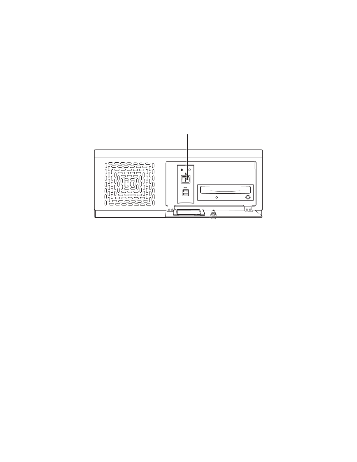
STARTING AND SHUTTING DOWN THE DX8000
This section describes how to start and shut down the DX8000 and includes the following topics:
• Starting the DX8000 on page 15
• Shutting Down the DX8000 on page 15
For information on logging in to the DX8000, refer to Logging In to the DX8000 Application on page 16.
STARTING THE DX8000
To start the DX8000:
1. Once the system is installed, open the front panel of the DVR and press the power switch.
POWER HDD
USB
2. Wait while the unit starts (this may take several minutes).
SHUTTING DOWN THE DX8000
You must have Power User or Administrator access to shut down. For information on users’ security levels, refer to Definition of User Access
Levels on page 173. You must also have a Windows password to shut down. For information on the Windows default password, refer to the
Important Security Information for System Administrators guide.
To sh ut do wn:
1. From the DX8000 menu bar, choose File > Exit. The Shut Down dialog box opens.
2. Select Shut down.
3. Click OK.
DX8000 DOCUMENTATION
You can print selected technical documentation free, directly from the Internet.
To access technical documentation:
1. Go to http://www.pelco.com/products/. The Pelco Products Web page is displayed.
2. Scroll to the Control Site Equipment section and click Video Recorders. The Control Site Equipment - Digital Video Recorders Web page is
displayed.
3. Scroll to the DX8000 and locate the specific document you want to view or print. Use Adobe
search for the sections you need, and print them on most standard printers. (Go to www.adobe.com to download a free copy of Acrobat
Reader.)
Figure 1. Front Panel and Power Switch
®
Acrobat Reader® to open the document,
C624M-C (5/06) 15
Page 16

Logging In to the DX8000 Application
To access the features of the DX8000 Series DVR, you must log in with a valid user name and password. The DX8000 comes equipped with a
built-in user account named “Guest.” Each time the unit is turned on, the Guest account is automatically activated. In addition to the Guest
account, there are four other user access levels, or groups, that can be configured on the DX8000. The Guest user is granted only limited access
to the system. The other four access levels range from the Administrator group, with the most rights and privileges, to the Restricted group, with
the least rights and privileges.
To operate and configure all but the most basic features of the DX8000, you must be assigned a user account other than Guest. If you have not
been assigned a user account, contact your system administrator before proceeding.
For information on the rights and permissions of the user groups, refer to Definition of User Access Levels on page 173.
NOTE: The Guest user account does not have access to the setup features of the DX8000. Only users with Administrator and Power User
accounts are allowed access to setup functions.
This section includes the following topics:
• Local DX8000 Login on page 16
• Remote DX8000 Login on page 17
LOCAL DX8000 LOGIN
If you are logging into the DX8000 for the first time, the login procedure is different from the method described below. For information on firsttime login instructions, refer to the DX8000 Installation manual.
This section includes the following topics:
• Logging in to a Local DX8000 on page 16
• Logging Out of the Local DX8000 on page 16
• Exiting to the Windows Operating System on page 17
LOGGING IN TO A LOCAL DX8000
You must have a valid user name and password to log in to the DX8000. The user name and password are case sensitive.
To log in with a user name other than Guest:
1. From the DX8000 main menu, go to File > User Log-in. The User Log-in dialog box opens.
2. Enter a valid user name in the User Name field and a valid password in the Password field.
3. Click OK.
LOGGING OUT OF THE LOCAL DX8000
Logging out of the local or a remote DVR does not disconnect you from that system. Logging out will return you to the Guest account.
To disconnect from a remote server, refer to Disconnecting from a Remote Site on page 17
To log the current user out of the system and return to the Guest account:
Click File > User Log-out.
You can also log out of a local or remote DVR by right-clicking its site name from the Site tree and then selecting User Log-Out from the
quick-menu.
16 C624M-C (5/06)
Page 17

EXITING TO THE WINDOWS OPERATING SYSTEM
You must have Administrator user access to exit to Windows. Refer to Definition of User Access Levels on page 173 for information on users’
security levels. You must have a Windows password to exit to the Windows operating system. For information on the Windows default
password, refer to the Important Security Information for System Administrators guide.
To exit the DX8000 application and log into the Windows operating system:
1. From the DX8000 menu bar, choose File > Exit. The Shut down dialog box opens.
2. Click Exit to Windows. The Shut down dialog box opens.
3. Click OK.
The Log On to Windows dialog box opens.
4. Enter the Windows password and then click OK. The system logs you into the Windows operating system.
REMOTE DX8000 LOGIN
You can view live and playback video from up to five DX8000 Series DVRs simultaneously. To access the features of a remote DX8000, a link must
be established between the local and remote DVRs. Refer to Adding a Remote Site on page 177 for instructions on establishing a network
connection with a remote DVR. After establishing an active connection, refer to Logging in to a Remote Site on page 17 for login instructions.
This section includes the following topics:
• Connecting to a Remote Site on page 17
• Disconnecting from a Remote Site on page 17
• Logging in to a Remote Site on page 17
• Logging Out of a Remote Site on page 18
CONNECTING TO A REMOTE SITE
To connect to an active DX8000 server on the network:
1. In the DX8000 main window, right-click the remote site name from the Site tree. The shortcut menu is displayed.
2. Select Connect from the shortcut menu.
DISCONNECTING FROM A REMOTE SITE
To terminate a connection with a remote DX8000 server:
1. In the DX8000 main window, right-click the remote site name from the Site tree. The shortcut menu is displayed.
2. Select Disconnect from the shortcut menu.
LOGGING IN TO A REMOTE SITE
After a connection to a remote site has been established, log in with a valid user name and password for that site.
To log in to a remote site:
1. In the DX8000 main window, select a remote DX8000 Series DVR site from the Site tree.
2. From the DX8000 menu bar, choose File > User Log-in.
You can also log in to a remote site by right-clicking its site name and then selecting User Log-In from the shortcut menu.
3. Enter a user name and password for the remote site.
C624M-C (5/06) 17
Page 18

LOGGING OUT OF A REMOTE SITE
Logging out of the local or a remote DVR does not disconnect you from that system. Logging out will return you to the Guest account.
To disconnect from a remote server, refer to Disconnecting from a Remote Site on page 17. You can only log out of one server at a time. If you are
logged into multiple servers, you must log out of each server individually. You can also log out of a local or remote DVR by right-clicking its site
name from the Site tree and selecting User Log-out from the quick-menu.
To log out of a local or remote DVR site:
From the DX8000 menu bar, choose File > User Log-out.
18 C624M-C (5/06)
Page 19

Understanding the DX8000 Application Window
This section describes the DX8000 application window and its operation. The application window is the central control center from where you
have access to the DX8000 features and functions.
• View both live and recorded video
• Exit to the Windows environment
• Access DX8000 setup features
• Control camera pan, tilt, and zoom functions
• Select cameras for viewing and recording
• Specify playback date and time
• Access playback controls
This section includes the following topics:
• Description of the DX8000 Main Window on page 19
• Understanding View Panes and Panels on page 26
• Working with the Site tree on page 31
DESCRIPTION OF THE DX8000 MAIN WINDOW
The application window is displayed after the DX8000 starts. The main window provides access to both live and recorded video.
This section describes the DX8000 main window and includes the following topics:
• DX8000 Menu Bar on page 22
• DX8000 Toolbar on page 25
• Displaying the DX8000 Window from a Page on page 26
• Description of Operating Modes on page 26
• Switching Between Standard and Extended Panel Views on page 26
C624M-C (5/06) 19
Page 20
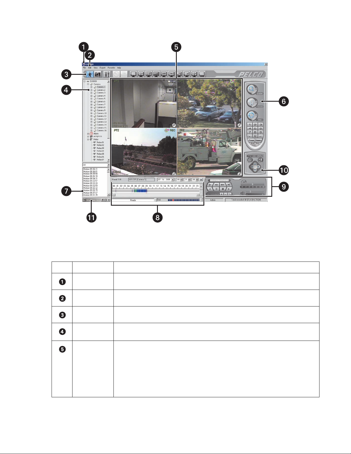
The following figure shows the parts of the DX8000 main window.
Figure 2. DX8000 DVR Main Window
The following table describes the parts of the DX8000 application window.
Table A. Parts of the DX8000 Application Window
Item Part Description
Title Bar Displays the DX8000 application title.
Menu Bar Provides access to drop-down menus.
Toolbar Provides access to display, setup, export, and search tools.
Site tree Displays top-down, hierarchical management of DX8000 resources, such as servers, cameras, alarms, and
relays.
View Panels Display live and playback video from attached cameras. A view panel consists of view panes.
• View pane: A view pane is a division of a view panel. Each view pane contains only a single camera
channel. Up to 36 view panes can fit in a single view panel.
• View panel: A view panel is made up of the entire DX8000 viewing area. View panels are divided into
multiple panes. A panel can display from one to 36 individual cameras.
For additional information about view panels and panes, refer to Understanding View Panes and Panels on
page 26.
20 C624M-C (5/06)
Page 21
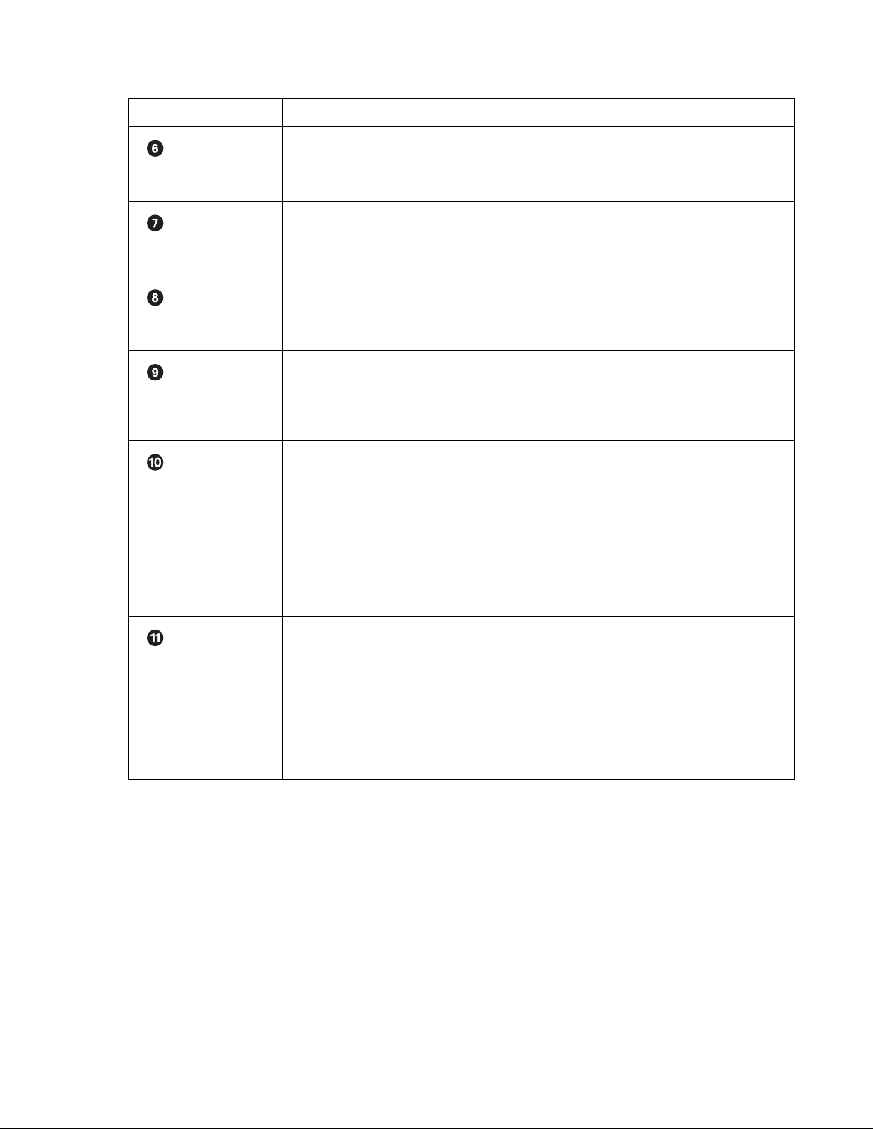
Table A. Parts of the DX8000 Application Window (Continued)
Item Part Description
PTZ Control Panel Allows users with access rights to operate camera lens control features and to program PTZ presets,
patterns, auxiliary outputs, and tours. This panel is hidden in the extended view mode. In this case, select the
standard view mode to display the PTZ control panel. For information on how to select view modes, refer to
Switching Between Standard and Extended Panel Views on page 26.
Index View Panel Allows users with access rights to search motion and alarm events within a 24-hour period specified in the
playback timeline. This panel is hidden in the extended view mode. In this case, select the standard view
mode to display the index view panel. For information on how to select view modes, refer to Switching
Between Standard and Extended Panel Views on page 26.
Playback Timeline Displays a 24-hour timeline marked with color-coded video events. Allows users with Standard User access
rights to select a date and time for playback. This panel is hidden in the extended view mode. In this case,
select the standard view mode to display the playback timeline. For information on how to select view modes,
refer to Switching Between Standard and Extended Panel Views on page 26.
Playback Control
Panel
Provides buttons for users with access rights to control video playback. Includes forward and reverse playback
and still image. It also provides controls for playback speed and volume. This panel is hidden in the extended
view mode. In this case, select the standard view mode to display the playback timeline control panel. For
information on how to select view modes, refer to Switching Between Standard and Extended Panel Views on
page 26.
PTZ OSD Menu or
Digital Zoom
Control
This control provides two functions depending on which mode the DX8000 is operating: live view or playback:
• Live View Mode: In the Live View mode, provides users with access rights to operate PTZ OSD
features. For information on using the PTZ OSD menu controls, refer to Using the PTZ OSD Menu Control
on page 51.This panel is hidden in the extended view mode. In this case, select the standard view mode
to display the playback zoom control. For information on how to select view modes, refer to Switching
Between Standard and Extended Panel Views on page 26.
• Playback Mode: In the Playback mode, provides users with access rights to operate digital zoom
features. This panel is hidden in the extended view mode. In this case, select the standard view mode to
display the playback zoom control. For information on how to select view modes, refer to Switching
Between Standard and Extended Panel Views on page 26.
Status Bar Displays current date and time, recorder processing status, disk status indicator, user name of currently
logged-in user, and total amount of recorded video. The status bar is hidden in the extended view mode.
In this case, select the standard view mode to display the status bar. For information on how to select view
modes, refer to Switching Between Standard and Extended Panel Views on page 26.
NOTE: As the storage array of the DX8000 fills beyond its capacity, video is deleted in a first-in, first-out
(FIFO) fashion. The disk status indicator on the status bar shows the amount of disk space used by recorded
video. The red indicator marks the current recording position of the disk array, blue indicators mark parts of
the array that are storing previously recorded video, and clear indicates that no video has been recorded in
that area of the array.
C624M-C (5/06) 21
Page 22

DX8000 MENU BAR
This section describes the DX8000 menu bar commands and includes the following topics:
• File Menu on page 22
• Edit Menu on page 22
• View Menu on page 23
• Export Menu on page 24
• Favorite Menu on page 24
• Help Menu on page 24
File Menu
The following table describes the DX8000 File menu commands.
Table B. File Menu Commands
Command Description
User Log-in Opens the User Log-In dialog box for entering the user name and password to log in to the DX8000.
User Log-out Immediately logs the current user out of the DX8000. The system returns to the default mode.
Software Upgrade Opens the Select Upgrade Package dialog box for selecting the source from which to access files to upgrade
the DX8000 software. This command is available only when you log in to the DX80000 as Administrator.
Password Recovery Opens the Password Recovery dialog box for entering the password provided by Pelco Product Support. For
more information, refer to Recovering a Password on page 215. For information on recovering a password,
contact Pelco Product Support.
Unplug/Eject Hardware Opens the Unplug or Eject Hardware dialog box for selecting the device you want to unplug or eject.
Exit Opens the Shut down dialog box for selecting one of the following actions (requires a certain level of user
permission):
• Shut down: Shuts down the DX8000 machine. You must have Power User or Administrator access to
shut down the DX8000 machine. For more information, refer to Shutting Down the DX8000 on page 15.
• Restart: Restarts the DX8000 application. You must have Administrator user access to restart the
DX8000 application. For more information, refer to User Setup on page 171.
• Exit to Windows mode: You must have Administrator user access to exit the DX8000 application to
the Windows operating system. For more information, refer to Exiting to the Windows Operating
System on page 17.
Edit Menu
The following table describes the DX8000 Edit menu commands.
Table C. Edit Menu Commands
Command Description
Export Setup Opens the DX8000 Setup File Export dialog box for exporting the DX8000 system configuration settings to a
specific file name and location. The Export feature also allows you to export the DX8000 settings to specified
location for later retrieval. For more information, refer to Using the Edit Menu to Perform an Export on
page 183.
Import Setup Opens the DX8000 Setup File Import dialog box for importing a DX8000 system configuration file. For more
information, refer to Using the Edit Menu to Perform an Export on page 183.
22 C624M-C (5/06)
Page 23

View Menu
The following table describes the DX8000 View menu commands.
Table D. View Menu Commands
Command Description
OSD Opens a submenu with the following choices:
• Site Name: A global setting that, when selected, displays a site’s name in the respective view pane.
• Camera Name: A global setting that, when selected, displays a camera’s name in the respective view
pane.
• Video Recording: A global setting that, when selected, displays an icon in the upper right corner of
the pane and enables video recording for the cameras assigned to a view pane.
• Audio Recording: A global setting that, when selected, enables audio recording for the cameras
assigned to a view pane. The DX8000 compresses audio data to save space. In this case, recorded
audio may not be of the same quality as live audio.
• PTZ: A global setting that, when selected, enables PTZ capability for the cameras assigned to a view
pane.
• Instant Recording: A global setting that, when selected, enables instant recording capability for the
cameras assigned to a view pane.
• POS: A global setting that, when selected, enables POS video recording for the cameras assigned to a
view pane.
• Select All: Selects all of the OSD options.
• Background Color: Opens a submenu with the following choices:
– Set Color: Opens the Colors palette for selecting or creating a background color.
– Disable Background: Disables a background color from being shown.
Log Opens a submenu with the following choices:
•System On/Off
• System Failure
•Export
• Backup
• Network Connection
• Login ID list with Time
• Video Loss
Resolution Opens a submenu with the following choices:
• 1024x768
• 1280x1024
Cycle Views Setup Opens a submenu with the following choices:
• Dwell time change: Opens a submenu with the following choices for assigning permission to a user
group, allowing the selected user group to change the dwell time:
– Restricted User Group
– Standard User Group
– Power User Group
• Dwell time: Opens a submenu of dwell times with the following choices:
–2 Sec.
–5 Sec.
–10 Sec.
–30 Sec.
–60 Sec.
Extended View Enlarges the video image displayed in the view pane.
Index View Opens the Event Index pane.
Display Deinterlaced Image Selects the deinterlace mode for enhancing the display of video images.
C624M-C (5/06) 23
Page 24

Export Menu
The following table describes the DX8000 Export menu commands.
Table E. Export Menu Commands
Command Description
Interrupt Export Immediately concludes an export process. If the Interrupt Export command is executed before the scheduled
backup time, the system will save the backed-up data up until the time the Interrupt Export command is
executed.
Cancel Export Immediately cancels the export process and no backed data retained.
Favorite Menu
The following table describes the DX8000 Favorite menu commands.
Table F. Favorite Menu Commands
Command Description
Add to Favorites Opens the Add to Favorites dialog box, where you create a favorite and store the favorite to a specified
folder.
Organize Favorites Opens the Organize Favorites dialog box, where you can do the following:
• Create a folders
• Rename folders
• Move favorites to a specific folder
• Delete a favorite or favorite folder
Help Menu
The following table describes the DX8000 Help menu commands.
Table G. DX8000 Help Menu Commands
Command Description
DX8000 Help Opens the DX8000 Help system.
About Provides model and version information for the DX8000 application.
24 C624M-C (5/06)
Page 25
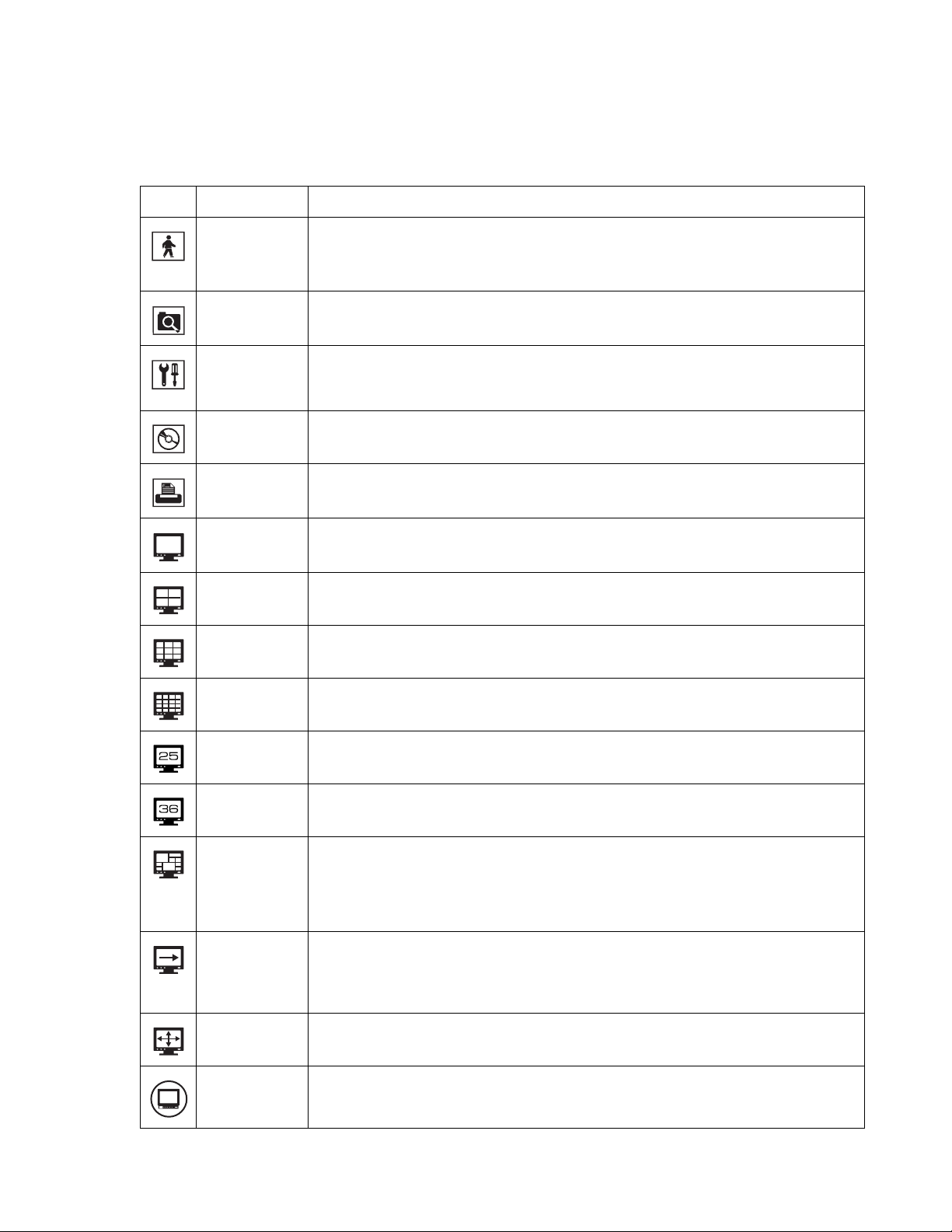
DX8000 TOOLBAR
This section describes the DX8000 toolbar. The following table describes the DX8000 toolbar buttons.
Table H. DX8000 Toolbar Buttons
Button Name Description
Live Enters the display mode and opens the DX8000 main window, where live and playback video is displayed:
• Live Mode: Allows all users to view live video.
• Playback Mode: Allows users with Standard User access and higher to play back recorded video.
Search Enters the Search mode and opens the search window, providing access to search features. Users with
Standard User access and higher are allowed to search video data using specific criteria.
Setup Enters the setup mode and opens the Setup dialog box to the Camera page (default view), and allows access
to the other pages. Users with Power User access and higher are allowed to set up the features and options
for the DVR.
Export Enters the export mode, where you configure the export options and parameters.
Print Enters the print mode, where you print the selected video image.
Single Division Displays one camera.
4 Division Displays four cameras at a time (quad display).
9 Division Displays nine cameras at a time.
16 Division Displays 16 cameras at a time.
25 Division Displays 25 images. Each DVR accommodates up to 16 cameras. You can display images from the local and
remote DX8000 DVRs.
36 Division Displays 36 images. Each DVR accommodates up to 16 cameras. You can display images from the local and
remote DX8000 DVRs.
6, 10, 13 Division Displays images as follows:
• 6 Division (1+5): One larger and five smaller images
• 10 Division (2+8): Two larger and eight smaller images
• 13 Division (1+12: One larger and 12 smaller images
Cycle Views Turns window cycling on and off. Automatically cycles through each view panel ensuring all cameras get
displayed. Group permission to change the dwell time is assigned by the Administrator to the following
groups: Restricted User Group, Standard User Group, and Power User Group. For information on cycle views
setup, refer to Automatically Cycling Through View Windows on page 29.
Full Screen Selects a full-window view. The application window is expanded to occupy the entire monitor screen. Click
the right mouse button to exit full-screen view.
External Monitor Opens the external monitor drop-down menu. For more information, refer to External Monitor Setup on
page 191.
C624M-C (5/06) 25
Page 26
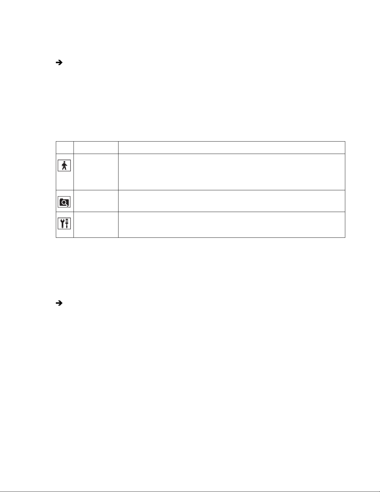
DISPLAYING THE DX8000 WINDOW FROM A PAGE
To display the DX8000 main window from a Setup dialog page:
On the DX8000 toolbar, click Live.
DESCRIPTION OF OPERATING MODES
The DX8000 Series DVR has four primary operating modes: Live, Playback, Search, and Setup. Each operating mode is accessed by clicking its
corresponding button on the toolbar.
The following table describes the DX8000 operating modes.
Table I. Operating Modes
Icon Mode Description
Live Enters the display mode and opens the DX8000 main window, where live and playback video is displayed:
• Live Mode: Allows all users to view live video.
• Playback Mode: Allows users with Standard User access and higher are allowed to play back recorded
video.
Search Enters the Search mode and opens the search window, providing access to search features. Users with
Standard User access and higher are allowed to search video data using specific criteria.
Setup Enters the setup mode and opens the Setup dialog box to the Camera setup page (default view), and allows
access to the other setup pages. Users with Power User access and higher are allowed to set up the features
and options for the DVR.
SWITCHING BETWEEN STANDARD AND EXTENDED PANEL VIEWS
The DX8000 features a viewing area that can be expanded to fill a larger portion of the main window. Extended view expands the viewable
panel containing camera panes but hides the timeline, PTZ, digital zoom, and playback controls. To use the timeline, PTZ, digital zoom, and
playback controls, you must take the DX8000 out of extended view.
To switch back and forth between standard and extended view:
From the DX8000 menu bar, choose View > Extended View.
UNDERSTANDING VIEW PANES AND PANELS
This section describes the DX8000 viewing area. The viewing area is organized into panes and panels, much like a window contains panes.
Video from each camera is displayed in its own viewing pane.
This section includes the following topics:
• Working with View Pane and Panel on page 26
• Configuring View Panels on page 27
• Navigating View Panels on page 27
WORKING WITH VIEW PANE AND PANEL
The DX8000 displays video from each camera in its own viewing pane.
• View pane: A view pane is a division of a view panel. Each view pane contains only a single camera channel. Up to 36 view panes can fit
in a single view panel.
• View panel: A view panel is made up of the entire DX8000 viewing area. View panels are divided into multiple panes. Each panel can
display from one to 36 individual cameras.
26 C624M-C (5/06)
Page 27
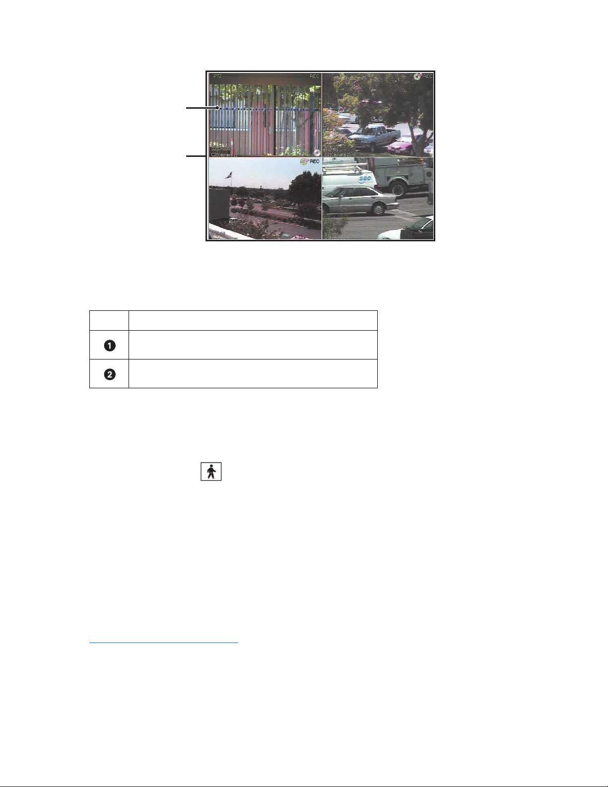
The following figure illustrates how the DX8000 viewing area is structured.
Figure 3. View Panes and Panel for 4-Division Display
The following table describes the view pane and panel as shown in the figure above.
Table J. View Panes Panel
Item Description
Shows a view pane for a for division display.
Shows the view panel, which contains view panes.
CONFIGURING VIEW PANELS
The DX8000 can display up to 36 cameras simultaneously in a single panel.
To select a view panel division:
1. On the DX8000 toolbar, click .
2. On the DX8000 toolbar, click a view panel division button.
For information on the view division buttons, refer to DX8000 Toolbar on page 25.
NAVIGATING VIEW PANELS
This section describes how to move between the DX8000 view panes and panels. This section includes the following topics:
• Navigating Between View Panels on page 27
• Expanding and Collapsing View Pane on page 29
• Manually Cycling Through Hidden View Panels on page 29
• Automatically Cycling Through View Windows on page 29
Navigating Between View Panels
The DX8000 allows you to monitor up to 36 channels: each channel is assigned to 1 pane within the view panel. If the 36-division display format
is selected, all 36 panes occupy one panel. However, for single, 4-division, 9-division, 16-division, and 25-division display formats, the DX8000
displays the panes in multiple panels. In this case, to view all of the panes, you must cycle through multiple panels to display hidden panels.
• Channel: As pertains to video, one DX8000 camera port (input). The term channel is sometimes used interchangeably with camera.
• Camera: One external video device, such as a Spectra III™, that provides input video to the DX8000 DVR.
For example, if you select the single-division display format, 1 channel (video pane) fills the entire panel.
C624M-C (5/06) 27
Page 28
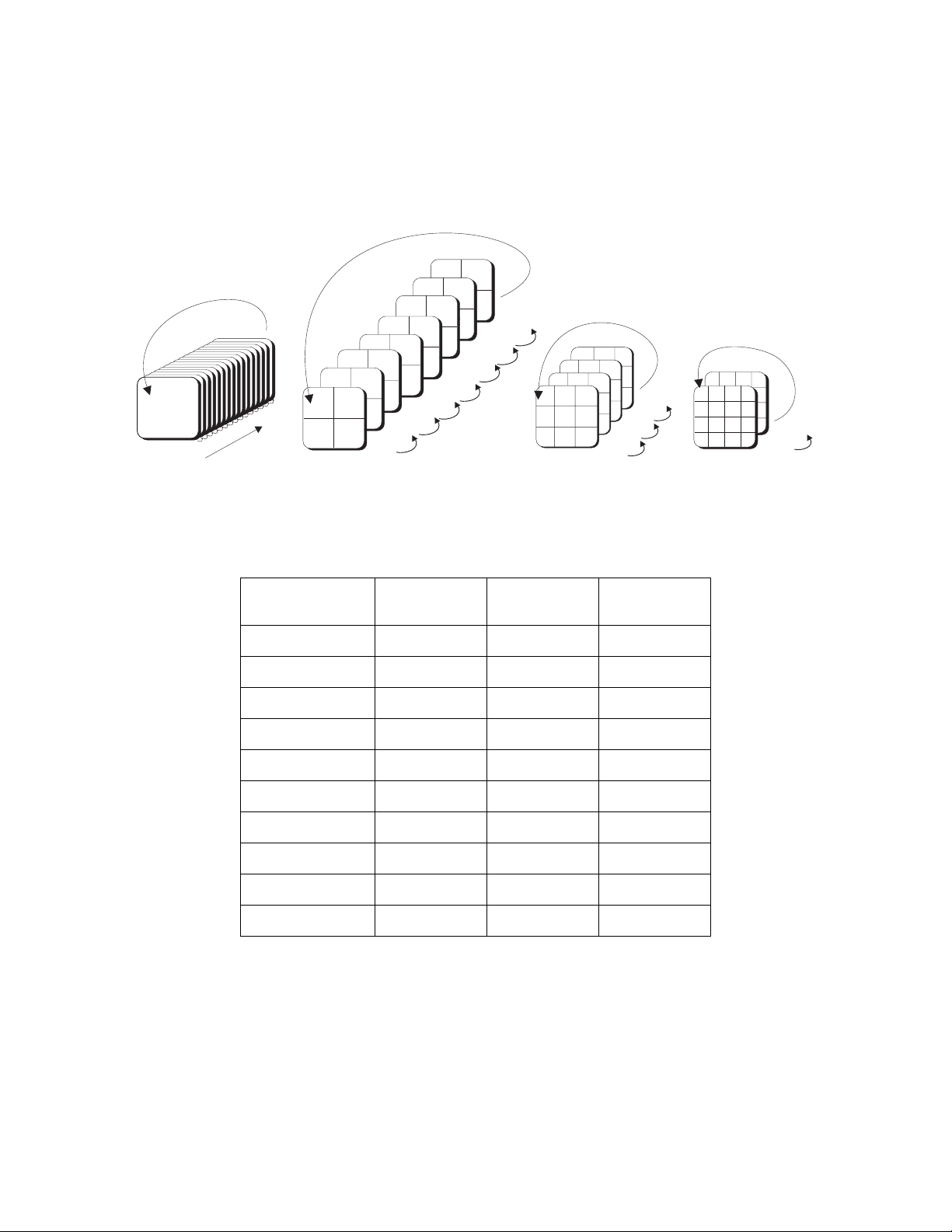
• The pane and panel represent the same amount of viewing area.
• In this case, there will be an additional 31 hidden panels (1 pane = 1 panel) available to cycle through.
Similarly, if you select the 4-division display format:
• Four panes (one camera/channel per pane) are displayed in the panel.
• In this case, 7 hidden panels (four cameras/channels per panel, which equals 4 x 7 = 28 panels), remain to be displayed.
The following figure shows how the DX8000 cycles through view panels, depending on the display format.
29 30
25 26
21 22
27
17 18
23
13 14
9
15
5
6
11 12
1
32
12
7
4
3
8
20
19
10
16
13 - 16
9 - 12
5 - 8
1 - 4
1
31
24
17 - 20
28
21 - 24
32
26 - 28
29 - 32
17 18 19
8 9 10
20 21 22
1 2 3
11 12 13
23 24 25
4 5 6
14 15 16
7 8 9
25 26 27
28 29 30
32 31 32
8 - 16
1 - 9
25 - 32
17 - 25
18
19
20
17
1
2
3
4
22
23
24
21
5
6
8
7
27
25
26
9
13
28
10
11
29
12
303231
15
16
14
Figure 4. Example of Single, 4, 9, and 16 Division View Panels
The following table describes how the DX8000 view panes and panels are organized.
17 - 32
1 - 16
Table K. How View Panels are Organized
Display Type Grouping
Number of
View Panes
Number of
View Panels
Single 1/32 1 32
4 Division 1/8 4 8
9 Division 1/4 9 4
16 Division 1/2 16 2
25 Division 1/2 25 2
36 Division 1/1 36 1
6, 10, 13 Division:
• 1+5 Division 1/6 6 6
• 2+8 Division 1/4 10 4
• 1+12 Division 1/4 13 4
Pressing one of the view panel division buttons sets the number of visible channels displayed in the panel. The following figure illustrates the
view panel identifier.
28 C624M-C (5/06)
Page 29
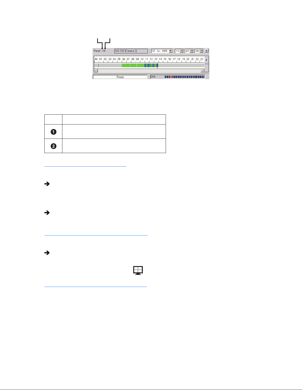
Figure 5. View Panel Identifier
The following table describes how the DX8000 view panes and panels shown in Figure 4 are organized.
Table L. View Panes and Panel
Item Description
Indicates the panel number being viewed.
Indicates how many pane are displayed per panel.
Expanding and Collapsing View Pane
To expand a view pane to fill the entire panel:
Double-click a view pane.
The view fills the entire view panel.
To collapse a view pane:
Double-click the expanded view pane.
The view pane returns to its default size.
Manually Cycling Through Hidden View Panels
To manually cycle through hidden view panels:
On the DX8000 toolbar, click one of the panel division buttons repeatedly.
The view sequences through the view panels.
For example for a 4 Division display format, if you click repeatedly, the DX8000 cycles through each of the eight available view panels.
Automatically Cycling Through View Windows
The DX8000 provides an automatic cycle feature that when selected, automatically cycles through each view panel ensuring all cameras get
displayed. Group permission to change the dwell time is assigned by the Administrator to the following groups: Restricted User Group, Standard
User Group, and Power User Group.
This section describes how to configure the DX8000 to automatically cycle through camera views and includes the following sections:
• Starting an Automatic Cycle View Mode on page 30
• Stopping an Automatic Cycle View Sequence on page 30
• Selecting User Groups to Set the Cycle View Dwell Time on page 30
• Selecting the Cycle View Dwell Time on page 30
C624M-C (5/06) 29
Page 30

Starting an Automatic Cycle View Mode
To start the automatic cycle view mode:
On the DX8000 toolbar, click Cycle Views.
The Cycle Views icon turns blue, indicating that the DX8000 is in the automatic cycle view mode. The system will cycle through each
panel, displaying each pane for the configured cycle view dwell time.
For example, if you, click , the automatic cycle view process starts.
Stopping an Automatic Cycle View Sequence
To stop the automatic cycle view mode:
On the DX8000 toolbar, click Cycle Views.
The DX8000 stops the automatic cycle view mode.
Selecting User Groups to Set the Cycle View Dwell Time
The DX8000 allows the Administrator to control which user group can change the cycle view dwell time. In this case, anyone that belongs to a
selected user group can change the cycle view dwell time.
To select a user group to have permission to change the cycle view dwell time:
1. On the DX8000 toolbar, click .
2. From the DX8000 menu bar, choose View > Cycle Views Setup > Dwell time change.
3. From the Dwell time change submenu, choose a user group.
Selecting the Cycle View Dwell Time
To configure the cycle period:
1. On the DX8000 toolbar, click .
2. From the DX8000 menu bar, choose View > Cycle Views Setup > Dwell time.
3. From the Dwell time submenu, choose a time period.
30 C624M-C (5/06)
Page 31
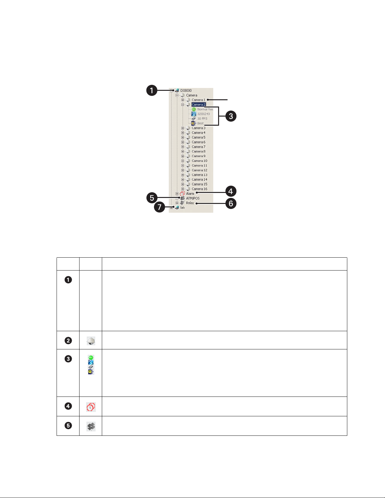
WORKING WITH THE SITE TREE
The Site tree provides access to DX8000 resources, such as cameras, alarm inputs, and relay outputs. Objects can be selected by clicking once
with the left mouse button and linked by dragging and dropping the icon into the view pane with the mouse. The Site tree information reflects
the current DX8000 server configuration.
The following figure shows the Site tree.
The following table describes the Site tree parts.
Item Part Description
Name Site: Expands and collapses the DX8000 site. Right-clicking the site name opens a shortcut menu that provides the
following commands:
• User Log-In: Clicking User Log-In opens the User Log-In dialog box, where you enter your user name and password
to log into the DX8000 site.
• User Log-Out: Clicking logs you out of the DX8000 site.
• Connect
• Disconnect
Camera: Expands and collapses the Camera tree.
Channel information: Displays icons that represent the configuration for the camera:
• Recording mode
• Recording resolution
• Recording frame rate
• Recording Image quality
Figure 6. Site tree Parts
Table M. Site tree Parts
Alarm: Expands and collapses the Alarm tree.
ATM/POS: Expands and collapses the ATM/POS tree.
C624M-C (5/06) 31
Page 32

Table M. Site tree Parts (Continued)
Item Part Description
Relay: Expands and collapses the Relay tree. Right-clicking a relay opens a shortcut menu that provides the following
commands:
• ON: Allows you to turn the relay on.
• OFF: Allows you to turn the relay off.
Remote site: Expands and collapses the remote DX8000 site. Right-clicking the remote site name opens a shortcut
menu that provides the following commands:
• User Log-In: Clicking User Log-In opens the User Log-In dialog box, where you enter your user name and password
to log into the remote DX8000 site.
• User Log-Out: Clicking logs you out of the remote DX8000 site.
• Connect: Allows you to connect to the remote site.
• Disconnect: Allows you to disconnect from the remote site.
This section describes how to work with the Site tree and includes the following topics:
• Assigning Cameras to View Panes on page 32
• Setting Up Links on page 32
• Removing Links on page 34
ASSIGNING CAMERAS TO VIEW PANES
The DX8000 provides view panes that are organized into view panels. The DX8000 includes 36 view panels that can display cameras from up to
five connected DVR sites. For information on view panels, refer to Working with View Pane and Panel on page 26.
The DX8000 Series DVR supports triplex operation. Triplex operation means that the DX8000 will continuously record even while users view
simultaneous live and playback video or modify the system setup.
To assign a single camera to a view pane:
1. On the DX8000 toolbar, click .
2. In the Site tree, click the plus sign (+) next to to expand the tree if necessary.
3. Do one of the following:
• To assign a single camera to a view pane, drag the camera from the Site tree onto a view pane.
• To assign all cameras from a single site to the view panes at once, drag onto a single view pane. (The default arrangement of
cameras is Camera1, Camera2, Camera3 – from left to right, top to bottom.)
4. Repeat the process in step 3 for up to 36 cameras from up to five DVR sites.
SETTING UP LINKS
The DX8000 allows you to set up links in various configurations:
• You can link multiple alarms and relays to a single camera.
• You can link a single alarm or relay to multiple cameras.
• You can link alarms and relays to cameras by dragging them onto individual camera view panes.
• You can also manually turn a relay on and off from the Site tree.
This section describes how to set up links and includes the following sections:
• Manually Turning a Relay On and Off on page 33
• Linking Alarm Inputs to a Camera on page 33
• Linking a Relay Output to a Camera on page 33
• Linking Relay Outputs to Alarm Inputs on page 33
32 C624M-C (5/06)
Page 33

Manually Turning a Relay On and Off
To manually turn a relay on and off:
1. Right click a relay. The shortcut menu opens.
2. Click ON or OFF to turn the relay OFF if it is on or ON if it is off.
Linking Alarm Inputs to a Camera
The DX8000 allows you link alarm inputs to a camera.
• You can link multiple alarm inputs to a single camera.
• You can also link a single alarm input to multiple cameras.
The DX8000 allows you link alarms to cameras by dragging them onto individual camera view panes.
To link an alarm input to a camera:
1. On the DX8000 toolbar, click .
2. In the Site tree, click the plus sign (+) next to the camera to which you want to link alarms.
3. Click the plus sign (+) next to the to see the list of alarm inputs.
4. Drag an alarm input onto a camera.
Linking a Relay Output to a Camera
The DX8000 allows you link relays to a camera.
• You can link multiple relays a single camera.
• You can also link a single relay to multiple cameras.
The DX8000 allows you link relays to cameras by dragging them onto individual camera view panes.
To link a relay output to a camera:
1. On the DX8000 toolbar, click .
2. In the Site tree, click the plus sign (+) next to the camera to which you want to link relays.
3. Click the plus sign (+) next to to see the list of relay outputs.
4. Drag a relay onto a camera.
Linking Relay Outputs to Alarm Inputs
To link a relay output to an alarm input:
1. On the DX8000 toolbar, click .
2. In the Site tree, click the plus sign (+) next to to expand the Alarm tree if needed.
Relays can also be linked to cameras and alarms on the Link settings page. For more information, refer to Configuring Basic Relay and
Alarm Settings on page 111.
3. Click the plus sign (+) next to to expand the Relay tree if needed.
4. Drag a relay output onto an alarm input.
C624M-C (5/06) 33
Page 34

REMOVING LINKS
This section describes how to remove links and includes the following sections:
• Removing a Linked Alarm Input from a Camera on page 34
• Removing a Linked Relay Output from a Camera on page 34
• Removing a Linked Relay Output from an Alarm Input on page 34
Removing a Linked Alarm Input from a Camera
To unlink an alarm from a camera:
1. On the DX8000 toolbar, click .
2. In the Site tree, click the plus sign (+) next to the camera from which you want to remove an alarm input.
3. Drag the alarm outside the Site tree panel, and then release the mouse button.
4. Repeat the above process for each alarm you want to remove.
Removing a Linked Relay Output from a Camera
To unlink a relay from a camera:
1. On the DX8000 toolbar, click .
2. In the Site tree, click the plus sign (+) next to the camera from which you want to remove the relay output.
3. Drag the relay outside the Site tree panel to the DX8000 toolbar or panel (above or below the Site tree panel), and then release the mouse
button.
4. Repeat the above process for each relay you want to remove.
Removing a Linked Relay Output from an Alarm Input
To unlink a relay from an alarm:
1. On the DX8000 toolbar, click .
2. In the Site tree, click the plus sign (+) next to the alarm input from which you want to remove the relay output.
3. Drag the relay outside the Site tree panel, and then release the mouse button.
4. Repeat the above process for each relay you want to remove.
34 C624M-C (5/06)
Page 35

Working in Live View Mode
This section describes how to use the DX8000 to view and record live video. All users can view live video from the main window. Users with
Standard User access and higher can operate the on-screen PTZ controls.
To view live video in the DX8000 main window:
On the DX8000 toolbar, click Live.
This section includes the following topics:
• Assigning Cameras to View Panes on page 35
• Live View On-Screen Display (OSD) on page 38
• Customizing the On-Screen Display (OSD) on page 39
ASSIGNING CAMERAS TO VIEW PANES
To assign a camera to the view pane:
1. Drag a camera from the Site tree onto a view pane.
2. Repeat the process in step 1 for up to 36 cameras from up to five different DX8000 sites.
For information about the DX8000 view pane and panels, refer to the following topics:
• Working with View Pane and Panel on page 26
• Configuring View Panels on page 27
• Navigating View Panels on page 27
SETTING UP FAVORITES
The DX8000 Favorites menu allows you to organize and save camera views. For example, you might want to display camera views that show the
delivery gate entrance for buildings 1, 4, 7, and 12 during the hours of 06:00 to 07:30 and another camera view that displays the front lobby of
building 1–16 at 08:00.
This section describes the following topics:
• Adding a Camera View to Favorites on page 35
• Organizing Favorites in Folders on page 36
ADDING A CAMERA VIEW TO FAVORITES
You can create multiple camera views to monitor various site locations. For example, you could create a folder named Day Shift for displaying
camera views during normal working hours and Night Shift for displaying various camera views after work and during the night hours. For
information about organizing favorites into folders, refer to Organizing Favorites in Folders on page 36.
To add a camera view to favorites:
1. From the DX8000 menu bar, click Add to Favorites.
The Add to Favorites dialog box opens.
Figure 7. Add to Favorites Dialog Box
C624M-C (5/06) 35
Page 36

2. Enter the camera view name in the Name text box.
3. Click OK. The camera view is added to the favorites, and the Add to Favorites dialog box closes.
4. To view the new entry, from the DX8000 menu bar, click Favorites. The new entry appears in the Favorites list.
Figure 8. Favorites Menu List
ORGANIZING FAVORITES IN FOLDERS
As your list of favorites grows, you can keep them organized by creating folders. You can organize your camera views by site name, user name,
and so forth. For example, you could create a folder named Day Shift for displaying camera views for the day shift.
Creating a Favorites Folder
To create a favorites folder:
1. From the DX8000 menu bar, click Organize Favorites.
The Organize Favorites dialog box opens.
Figure 9. Organize Favorites Dialog Box
2. Click Create Folder. A new folder is added to the favorites area.
3. To name the folder, do one of the following:
a. If the new folder name is already selected, type the name of the folder.
or
b. If the new folder name is not selected:
(1) Click the new folder.
(2) Type the name of the folder.
The new folder is listed in the Favorites area of the Organize Favorites dialog box and in the Favorites menu.
36 C624M-C (5/06)
Page 37

Organizing Favorites in Folders
To organize existing favorites into folders:
1. Create a favorites folder.
For information about creating a favorites folder, refer to Creating a Favorites Folder on page 36.
2. From the DX8000 menu bar, click Organize Favorites.
The Organize Favorites dialog box opens. A list of the current favorites and folders is displayed in the favorites area.
Figure 10. Organize Favorites Dialog Box and List of Favorites and Folders
3. In the favorites area, click a favorite.
4. Click Move to Folder.
The Move to Folder dialog box opens.
Figure 11. Move to Folders Dialog Box
5. Select a destination folder.
6. Click OK.
The favorite is moved under the destination folder.
C624M-C (5/06) 37
Page 38

LIVE VIEW ON-SCREEN DISPLAY (OSD)
The DX8000’s OSD consists of camera and site information that is superimposed on each view pane. Each display item in the OSD can be
customized for both live and playback viewing.
The following figure shows the Live View OSD pane.
Figure 12. Live View OSD Pane
The following table describes the parts of the Live View OSD pane.
Table N. Parts of the Live View OSD Pane
Item Part Description
PTZ Indicates that the PTZ control is enabled.
Indicates that audio recording is enabled. The DX8000 compresses audio data to save space. In this case,
recorded audio may not be of the same quality as live audio.
REC Indicates camera recording mode and status. A blinking REC indicator signifies event recording.
• Green indicates normal recording.
• Blue indicates motion recording.
• Red indicates alarm recording.
• Yellow indicates event recording.
• Purple indicates video loss recording.
Site Designator Lists the number and name of the current site.
Camera Designator Lists the number and name of the current camera.
On-Screen PTZ
Control
Instant Recording Starts/stops instant recording if enabled.
Facilitates mouse control of PTZ functions. Refer to Operating the On-Screen Pan, Tilt, and Zoom (PTZ)
Controls on page 41.
38 C624M-C (5/06)
Page 39
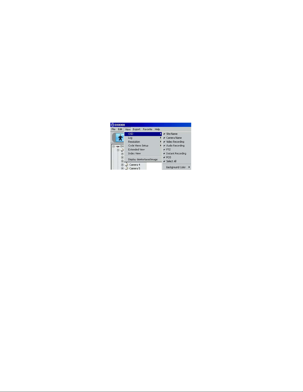
CUSTOMIZING THE ON-SCREEN DISPLAY (OSD)
Users with Guest and Power User access and higher can add and delete on-screen display items.
To customize the on-screen display:
1. From the DX8000 menu bar, choose View > OSD and then select the items you want to add to or delete from the OSD. Items include
•Site Name
• Camera Name
• Video Recording
• Audio Recording
•PTZ
• Instant Recording
•POS
• Select All (displays all items in each pane)
• Background Color
2. Do one of the following:
• From the DX8000 menu bar, choose View > OSD > Background Color > Set Color to add a contrasting background field behind each
OSD display item.
• From the DX8000 menu bar, choose View > OSD > Background Color > Disable Background to remove background field.
INSTANT RECORDING
This section describes the instant recording mode. Users with Power User access and higher can configure the DX8000 for recording video both
instantly and in accordance with a preset schedule. The Instant Recording mode is enabled from the Schedule page. Instant recording is
activated from the main window by double-clicking the Instant Recording icon.
If the DVR is not in the normal recording mode, you can use the instant recording mode to manually start and stop a video recording session
instantly. For information about adding the Instant Recording icon to the OSD, refer to Adding Instant Recording to OSD on page 40.
This section includes the following topics:
• Enabling and Disabling Instant Recording on page 39
• Adding Instant Recording to OSD on page 40
• Starting and Stopping Instant Recording on page 40
ENABLING AND DISABLING INSTANT RECORDING
This section describes how to enable and disable the instant recording mode and includes the following topics:
• Enabling Instant Recording on page 40
• Disabling Instant Recording on page 40
Figure 13. DX8000 DVR OSD Menu Options
For more information on instant recording, refer to Instant Recording on page 39.
C624M-C (5/06) 39
Page 40

Enabling Instant Recording
To enable the Instant Recording mode:
1. On the DX8000 toolbar, click . The Setup dialog box opens to the Camera page.
2. In the Setup dialog box, click .
3. In the Camera Settings Panel, from the Instant Recording drop-down box, select Enable.
Disabling Instant Recording
To disable the Instant Recording mode:
1. On the DX8000 toolbar, click . The Setup dialog box opens to the Camera page.
2. In the Setup dialog box, click .
3. In the Camera Settings Panel, from the Instant Recording drop-down box, select Disable.
ADDING INSTANT RECORDING TO OSD
To add the Instant Recording icon to the OSD:
From the DX8000 menu bar, choose View > OSD > Instant Recording.
The Instant Record icon is displayed in the lower-right corner of the view pane.
STARTING AND STOPPING INSTANT RECORDING
The Instant Recording mode must first be enabled from the Schedule page and the Instant Recording icon must be visible in the lower-right
corner of the view pane. For more information on DX8000 instant recording, refer to Instant Recording on page 39. For information on OSD, refer
to Live View On-Screen Display (OSD) on page 38.
The following figure shows the Record and Instant Record icons.
Figure 14. Activating Instant Recording
40 C624M-C (5/06)
Page 41
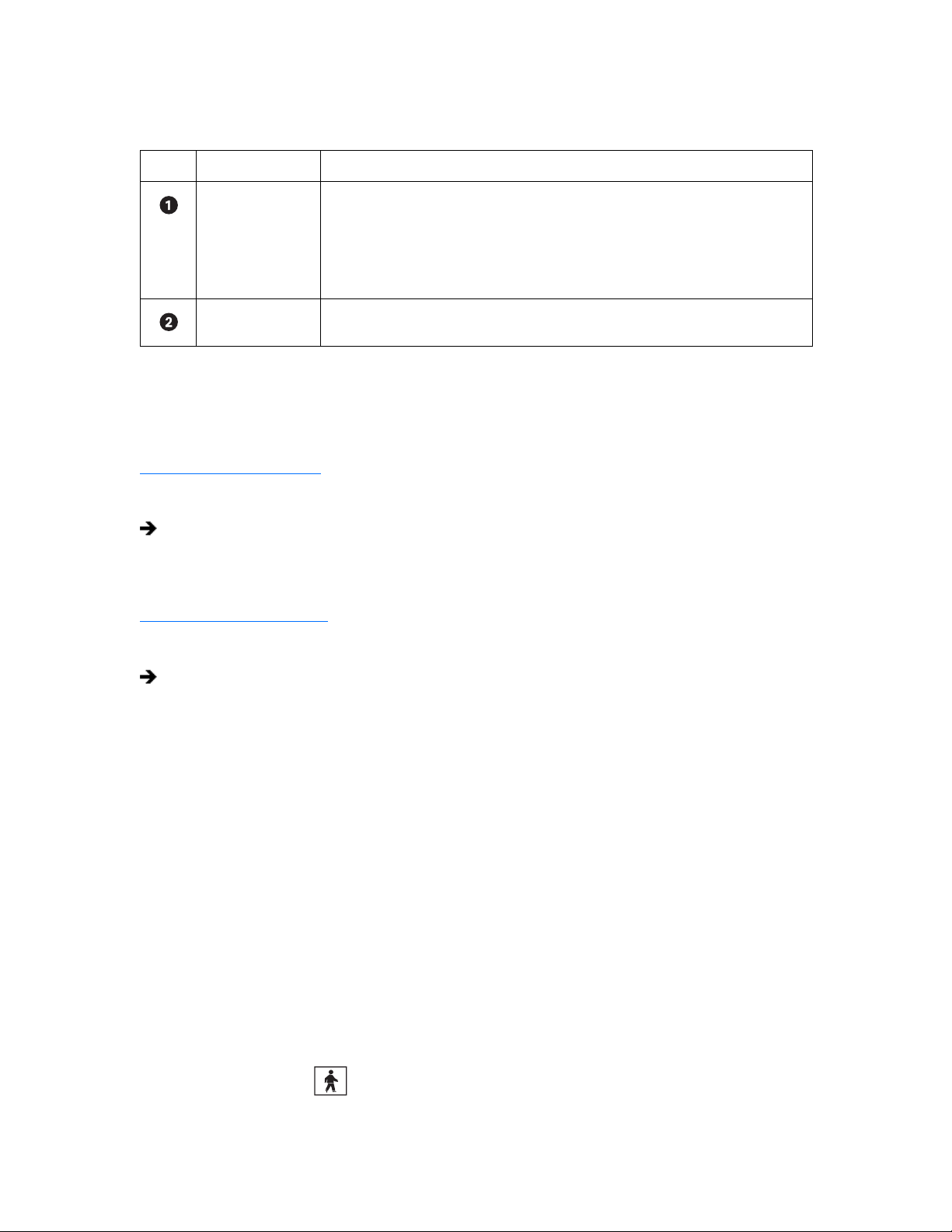
The following table describes the instant recording indicators.
Table O. Instant Recording Indicators
Item Icon Description
REC Indicates camera recording mode and status. A blinking REC indicator signifies event recording.
• Green indicates normal recording.
• Blue indicates motion recording.
• Red indicates alarm recording.
• Yellow indicates ATM/POS recording.
Instant Recording Starts/stops instant recording if enabled. Changes from silver to blue to indicate that instant
recording is activated.
This section describes how to start and stop instant recording and includes the following topics:
• Starting Instant Recording on page 41
• Stopping Instant Recording on page 41
Starting Instant Recording
To start instant recording:
Double-click the Instant Recording icon located in the lower-right corner of the view pane.
• The Instant Recording icon changes from silver to blue, indicating that instant recording is activated.
• If video recording is enabled, verify that REC is highlighted white. If video recording is not enabled, REC is not displayed.
Stopping Instant Recording
To deactivate instant recording:
In the view pane, double-click the Instant Recording icon.
OPERATING THE ON-SCREEN PAN, TILT, AND ZOOM (PTZ) CONTROLS
Users with Standard User access and higher may operate pan, tilt, and zoom lens functions of cameras that support such features. PTZ functions
can be controlled on-screen in Live mode using the mouse.
®
PTZ control is available only for cameras that support PTZ functions using Pelco’s P, D, or Coaxitron
configuring PTZ ports, refer to Setting Up COM1 and COM2 Port Properties on page 149. In addition, the PTZ option must be enabled and a
protocol must be assigned to the camera channel. For more information, refer to Camera Setup on page 105.
This section describes how to use the PTZ controls and includes the following topics:
• Operating the PTZ Controls on page 41
• Adjusting the Camera Lens on page 43
• Adjusting the Camera Zoom on page 44
• Using PC Keyboard Shortcuts to Operate PTZ and Lens Functions on page 45
OPERATING THE PTZ CONTROLS
To operate the on-screen PTZ controls:
protocols. For more information about
1. On the DX8000 toolbar, click .
2. Select a PTZ-enabled camera from the Site tree.
C624M-C (5/06) 41
Page 42

3. Place the mouse pointer in the middle of the camera’s view pane. The mouse pointer will change to a black cross when on-screen PTZ
control is available.
Figure 15. On-Screen PTZ Control
4. Click and hold the left mouse button, and then drag the mouse pointer in the direction you want to move the camera. The display changes
to an arrow, indicating the direction of the mouse.
Figure 16. On-Screen PTZ Movement
5. Release the mouse button when you have repositioned the camera to the desired location.
42 C624M-C (5/06)
Page 43
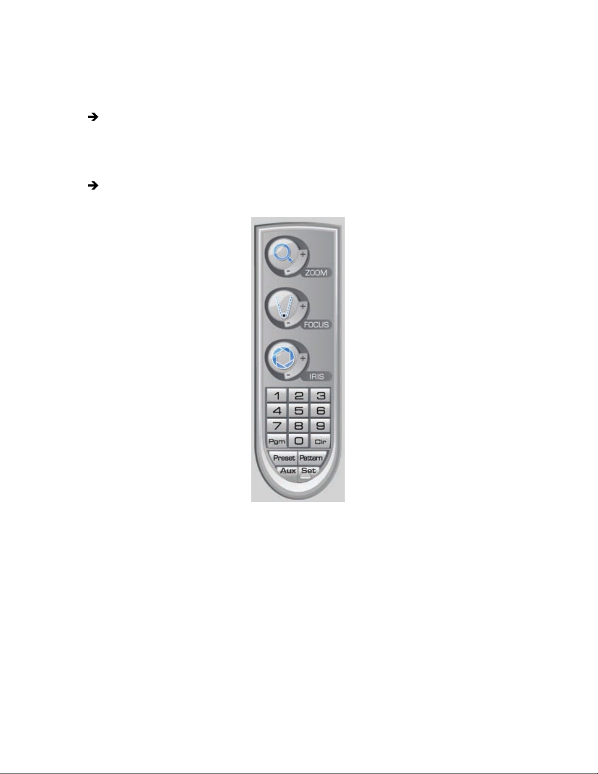
ADJUSTING THE CAMERA LENS
The keypad is hidden in the extended view mode. In this case, select the standard view mode to display the keypad.
To switch between the standard and extended view mode:
From the DX8000 menu bar, choose View > Extended View.
For information on changing view modes, refer to Switching Between Standard and Extended Panel Views on page 26.
To adjust camera lens features:
Click the plus (+) or minus (-) button next to the zoom, focus, and iris function on the keypad.
Figure 17. PTZ Keypad with Camera Lens Controls
C624M-C (5/06) 43
Page 44

ADJUSTING THE CAMERA ZOOM
To adjust camera zoom using the mouse:
Rotate the mouse wheel forward to zoom in and backward to zoom out.
The following figure shows how to operate the mouse to zoom in and out. You can also use keyboard shortcuts to operate the lens features of
cameras such as Pelco’s Spectra III. For more information about using keyboard shortcuts, refer to Using PC Keyboard Shortcuts to Operate PTZ
and Lens Functions on page 45.
Figure 18. Mouse Wheel Zoom
44 C624M-C (5/06)
Page 45

USING PC KEYBOARD SHORTCUTS TO OPERATE PTZ AND LENS FUNCTIONS
Users with Standard User access and higher may use a PC keyboard to operate PTZ and lens functions of cameras that support such features. PTZ
and lens functions can be controlled in Live mode using the keyboard.
The following table describes the keyboard buttons that you use to control PTZ and lens functions.
Table P. Standard PC Keyboard Functions for Controlling PTZ and Lens Functions
Key Description
Insert and Delete These keys provide the following functionality:
• On-screen display, preset and pattern modes: Insert increases and Delete decreases focus,
performing the same actions as the focus control on the PTZ keypad.
• Remote camera programming mode: Insert and Delete perform the same actions as the PTZ keypad
focus (+) and (-) buttons, navigating up and down the camera menu choices.
Home and End These keys provide the following functionality:
• On-screen display, preset and pattern modes: The Home key opens and the End key closes the iris,
performing the same actions as the PTZ keypad iris (+) and (-) buttons.
• Remote camera programming mode: The Home key selects an option from the camera’s on-screen
menu. The End key cancels an option or exit a menu. These keys perform the same actions as the PTZ
keypad iris (+) and (-) buttons.
Page Up and Page Down These keys perform the same functionality in the on-screen display and the preset and pattern modes as the
PTZ keypad zoom (+) and (-) buttons. Page Up zooms in; Page Down zooms out.
Up and Down Arrows These keys provide the following functionality:
• On-screen display, preset and pattern modes: The up arrow key raises the camera and the down
arrow key lowers the camera. The keys perform the same actions as the mouse to move the camera.
• Remote camera programming mode: The arrow keys navigate up and down the camera menu
choices. The keys perform the same actions as the PTZ keypad focus (+) and (-) buttons.
Left and Right Arrows These keys provide the same actions as using the mouse to move the camera. The left arrow key pans the
camera to the left and the right arrow key pans the camera to the right.
+ and - These keys perform similar actions as using the mouse to change the speed of camera movement. The plus
(+) key, pressed once increases the camera’s pan and tilt speed. The minus (-) key pressed once decreases the
camera’s pan and tilt speed. Each time the plus (+) key is pressed the pan and tilt speed is increased toward
the maximum speed. Each time the minus (-) key is pressed, the pan and tilt speed is decreased toward the
minimum speed.
To use the keyboard (+) and (-) keys to control camera pan and tilt speed:
1. On the DX8000 toolbar, click .
2. Select a PTZ-enabled camera from the Site tree.
3. Click the mouse pointer in the camera’s view panel.
4. Press and hold the up/down and left/right arrows to pan and tilt the camera.
5. Press the plus (+) key once or more to increase the pan and tilt speed. Press the minus (-) key once or more to decrease the pan and tilt
speed.
C624M-C (5/06) 45
Page 46

PTZ PRESETS
A preset is a user-defined camera position using pan and tilt, zoom, and focus commands (camera’s auto focus option must be off). Only cameras
that support positioning and programming using D, P, or Coaxitron protocols can use this feature. The DX8000 Series DVR can address up to 32
PTZ presets (1-32). Preset 95 is reserved for remote camera setup, and preset 99 is reserved for camera autoscan mode.
The PTZ controls are hidden in the extended view mode. In this case, select the standard view mode to display the PTZ controls.
To switch between the standard and extended view mode:
From the DX8000 menu bar, choose View > Extended View.
For information on changing view modes, refer to Switching Between Standard and Extended Panel Views on page 26.
The following PTZ operating guidelines must be observed:
• To program or clear presets, preset tours, and patterns, the icon must be engaged.
• To activate presets, tours, and patterns, the icon must be disengaged.
This section describes how to program, activate, and clear presets and includes the following topics:
• Programming a Preset on page 46
• Activating a Preset on page 47
• Clearing a Preset on page 48
PROGRAMMING A PRESET
This section describes how to program a preset. The following PTZ operating guidelines apply:
• Clicking the icon places DX8000 in PTZ programming mode.
• While in PTZ programming mode, multiple presets can be programmed until the icon is pressed again.
To program a PTZ preset:
1. On the DX8000 toolbar, click .
2. Drag a camera from the Site tree onto a view panel.
3. Click .
4. Using the on-screen PTZ controls and PTZ keypad, move the camera to the desired position and adjust the zoom setting.
EXIT
Figure 19. Creating a Preset
46 C624M-C (5/06)
Page 47

5. Using the PTZ keypad, select a number for the new preset (for example, 1).
6. Click to store the preset in the selected memory location.
7. Repeat steps 4-6 for each preset you want to program.
8. Click again to exit programming mode.
Figure 20. Programming a Preset
ACTIVATING A PRESET
Double-digit presets can be set or activated by pressing the first digit and then the second digit sequentially. For example, preset 20 can be
selected by clicking the number 2 and then the number 0 on the PTZ keypad.
To activate a preset:
1. On the DX8000 keypad, click a preset number (1-32) on the keypad.
2. Click to activate preset. The camera repositions to the new preset.
Figure 21. Activating a Preset
C624M-C (5/06) 47
Page 48

CLEARING A PRESET
To clear a preset:
1. On the DX8000 keypad, click to enter programming mode.
2. Click the number of the preset you want to clear from the PTZ keypad.
3. Click .
4. Repeat steps 2 and 3 to clear multiple presets.
5. Click to exit programming mode.
Figure 22. Clearing a Preset
PTZ PATTERNS
A pattern is a user-defined, viewable camera path with a definite beginning and end. Patterns are made up of a sequence of standard pan, tilt
and lens commands. Patterns are stored in the internal memory of the PTZ device, such as a Spectra® dome, that is connected to the DX8000.
Depending on the type and configuration of the PTZ device, the DX8000 can address up to four unique PTZ patterns. Once defined, a pattern can
be activated with a series of on-screen commands. A pattern will run continuously until it is deactivated.
Only PTZ-enabled cameras that support pattern programming through D, P, or Coaxitron protocols can use this feature.
The PTZ controls are hidden in the extended view mode. In this case, select the standard view mode to display the PTZ controls.
To switch between the standard and extended view mode:
From the DX8000 menu bar, choose View > Extended View.
This section describes how to program, activate, and clear patterns, and access the programming features of remote cameras. This section
includes the following topics:
• Programming a Pattern on page 49
• Activating a Pattern on page 50
• Clearing a Pattern on page 50
• Accessing Programming Features of Remote Cameras on page 51
48 C624M-C (5/06)
Page 49

PROGRAMMING A PATTERN
This section describes how to program a pattern. Certain PTZ devices, such as Pelco’s Spectra series domes, will display an on-screen message
stating the amount of remaining memory available for pattern programming.
Start Programming a Pattern
To program a pattern:
1. On the DX8000 toolbar, click .
2. Drag a camera from the Site tree onto a view panel.
3. On the DX8000 keypad, click to enter programming mode.
4. Using the PTZ keypad, select a number for the pattern (1 to 4).
5. Click .
6. Move the camera through a series of movements using the on-screen pan and tilt, zoom, and focus controls.
Stop Programming a Pattern
To stop programming a pattern:
1. On the DX8000 keypad, click .
2. Click .
Figure 23. Programming a Pattern
C624M-C (5/06) 49
Page 50

ACTIVATING A PATTERN
When activated, a pattern will repeat indefinitely until it is cleared, another pattern is set, or the on-screen PTZ control is moved.
To activate a pattern:
1. On the DX8000 keypad, click a pattern number (1 to 4) on the keypad.
2. Click .
Figure 24. Activating a Pattern
CLEARING A PATTERN
To clear a pattern:
1. On the DX8000 keypad, click to enter programming mode.
2. Select a pattern number (1 to 4) on the keypad.
3. Click .
4. Click .
5. Click again.
6. Click again to exit programming mode.
Figure 25. Clearing a Pattern
50 C624M-C (5/06)
Page 51

ACCESSING PROGRAMMING FEATURES OF REMOTE CAMERAS
You can use the PTZ function to program features of remote cameras, such as Pelco’s Spectra or Esprit®. Only cameras that support remote
programming through D, P, or Coaxitron protocols can use this feature.
The DX8000 allows you to navigate the remote camera menu system using any of the following:
• PTZ OSD Menu controls. For information on using the PTZ OSD Menu controls, refer to Using the PTZ OSD Menu Control on page 51.
• Keypad controls. For information on using the keypad controls, refer to Accessing a Remote Camera Programming Menu on page 52.
• Keyboard keys. For information on using the keyboard keys, refer to Using PC Keyboard Shortcuts to Operate PTZ and Lens Functions on
page 45.
The PTZ controls are hidden in the extended view mode. In this case, select the standard view mode to display the PTZ controls.
To switch between the standard and extended view mode:
From the DX8000 menu bar, choose View > Extended View.
This section describes how to access the programming features of remote cameras and includes the following topics:
• Using the PTZ OSD Menu Control on page 51
• Accessing a Remote Camera Programming Menu on page 52
Using the PTZ OSD Menu Control
The DX8000 allows you to navigate the menu system of remote cameras using the PTZ OSD Menu control. The PTZ OSD Menu control is
available when the DX8000 is in Live View mode. The PTZ controls are hidden in the extended view mode. In this case, select the standard view
mode to display the PTZ controls.
To switch between the standard and extended view mode:
From the DX8000 menu bar, choose View > Extended View.
Alternative methods to navigate the remote camera menu system are as follows:
• Keypad controls. For information on using the keypad controls, refer to Accessing a Remote Camera Programming Menu on page 52.
• Keyboard keys. For information on using the keyboard keys, refer to Using PC Keyboard Shortcuts to Operate PTZ and Lens Functions on
page 45.
The following figure shows the PTZ OSD Menu control.
Figure 26. PTZ OSD Menu
C624M-C (5/06) 51
Page 52

The following table describes the parts of the PTZ OSD Menu control.
Table Q. Parts of the PTZ OSD Menu Control
Item Part Description
Enter Provides the following actions:
• Accepts the selected remote camera OSD menu choice.
• Accesses menu option parameters. For example, if the cursor points to the Language option, clicking
Enter accesses the list of available languages.
Exit N/A
Up and Down
Navigate up and down the remote camera OSD menu or cycle through a list of options are parameters.
Buttons
Left and Right
Perform no activity.
Buttons
Accessing a Remote Camera Programming Menu
The DX8000 allows you to navigate the remote camera menu system using any of the following:
• PTZ OSD Menu controls. For information on using the PTZ OSD Menu controls, refer to Using the PTZ OSD Menu Control on page 51.
• Keypad controls. For information on using the keypad controls, refer to Accessing a Remote Camera Programming Menu on page 52.
• Keyboard keys. For information on using the keyboard keys, refer to Using PC Keyboard Shortcuts to Operate PTZ and Lens Functions on
page 45.
The following procedure instructs you to use the PTZ OSD Menu control to navigate the remote camera programming menu.
To access a programming menu for a remote camera:
1. On the DX8000 toolbar, click .
2. Drag a remote camera from the Site tree onto a view panel.
For certain camera models, you can also select preset number 95 from the keypad to access remote setup mode.
3. To access remote camera setup mode, do one of the following:
• On the DX8000 keypad, click from the keypad.
• Click , 9, 5, and from the PTZ keypad.
Figure 27. PTZ Control Panel
52 C624M-C (5/06)
Page 53
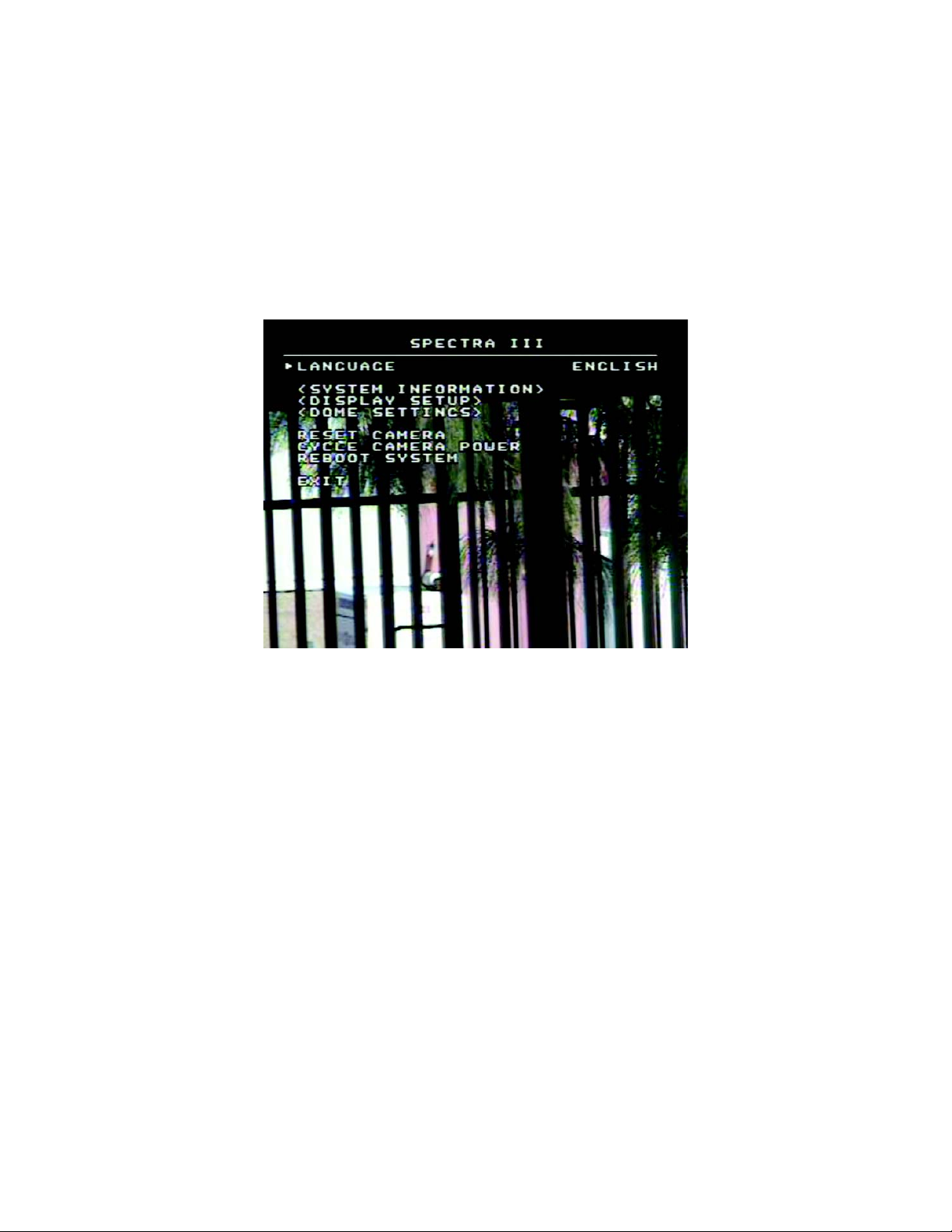
4. To navigate up and down camera menu choices, do one of the following:
• Use the PTZ OSD Menu controls.
• Use the on-screen PTZ controls or the focus (+) and focus (-) buttons.
5. To select an option from the camera’s on-screen menu, do one of the following:
• On the PTZ OSD Menu, click Enter.
• On the keypad, click the iris (+) button.
6. Click the iris (-) button to cancel an option or select the Exit command.
You can also use the on-screen PTZ controls with your mouse to navigate camera menus. Click and drag the mouse up or down to move
between menu options.
7. Click the iris (+) button to select the option or exit a menu when the cursor is at the Exit command.
Figure 28. Camera Setup Menu
C624M-C (5/06) 53
Page 54

SENDING AUXILIARY COMMANDS TO A DEVICE
The DX8000 auxiliary feature allows you to control external equipment connected to the auxiliary outputs of Spectra domes or Esprit positioning
systems. The auxiliary function is implemented through the D protocol and P protocol. In this case, the attached camera and DX8000 must be
configured to communicate using one of these protocols.
The Aux key selects the auxiliary mode. Buttons 1–4 select which of the camera’s auxiliary outputs to operate. Buttons 1–4 operate as a toggle
(on/off) each time they are clicked.
For example, an Esprit equipped with a wiper uses Aux 1 to control the wiper. In this case, pressing Aux and then 1 sends a command to the
Esprit to operate the wiper. You must configure the camera to establish how the camera responds to an auxiliary command. For detailed
information about how a specific Spectra or Esprit camera system interprets auxiliary commands, refer to the documentation that accompanies
your Spectra or Esprit camera system.
To send an auxiliary command:
1. On the DX8000 keypad, click to enter the programming mode.
2. Select the camera in the DX8000 view panel to which you want to send the auxiliary command.
3. Click the Aux button. Keypad buttons 1–4 are available.
Figure 29. Auxiliary (Aux) Button
The following figure shows that keypad buttons 1–4 are available.
Figure 30. Keypad Buttons 1–4 are Available
4. Click a keypad button (1–4). The auxiliary function assigned by camera for the selected button is executed.
54 C624M-C (5/06)
Page 55

CONFIGURING PRESET TOURS
A preset tour allows a camera to move through a programmed sequence of PTZ presets. The DX8000 Series DVR can store up to four preset
tours. While four tours can be programmed, only one tour can be activated at a time. A preset tour will operate continuously until another PTZ
control action is performed. At least one PTZ preset must be set in order to create a preset tour.
The PTZ controls are hidden in the extended view mode. In this case, select the standard view mode to display the PTZ controls.
To switch between the standard and extended view mode:
From the DX8000 menu bar, choose View > Extended View.
This section describes how to configure preset tours and includes the following topics:
• Programming a Preset Tour on page 55
• Activating a Preset Tour on page 58
• Deactivating a Preset Tour on page 58
PROGRAMMING A PRESET TOUR
This section describes how to program a preset tour and includes the following topics:
• Accessing a Preset Tour Group on page 55
• Adding Presets to a Tour on page 56
• Deleting Presets from a Tour on page 57
Accessing a Preset Tour Group
To access the “Preset tour group” dialog box:
1. On the DX8000 toolbar, click .
2. On the DX8000 keypad, click and then on the PTZ keypad. The Preset tour group dialog box opens.
3. Select the preset tour (1-4) that you want to program from the drop-down box.
4. Do one of the following:
• To add presets to a tour, refer to Adding Presets to a Tour on page 56.
• To delete presets from a tour, refer to Deleting Presets from a Tour on page 57.
Figure 31. Preset Tour Dialog Box
C624M-C (5/06) 55
Page 56

Adding Presets to a Tour
To add presets to a tour:
1. Access the Preset tour group dialog box. For information on accessing the Preset tour group dialog box, refer to Accessing a Preset Tour
Group on page 55.
2. Click the check box next to one of the presets you want to add to the tour.
3. Double-click within the Dwell Time field of the preset and increase or decrease the time in seconds the camera will remain on the preset
during that sequence of the tour.
4. Repeat steps 1 and 2 for each additional preset you want to add to the tour.
5. Click Add to Group.
6. Click Save.
7. Click Exit to return to the main screen.
Figure 32. Adding Preset to Tour
56 C624M-C (5/06)
Page 57

Deleting Presets from a Tour
To delete presets from a tour:
1. Access the Preset tour group dialog box. For information on accessing the Preset tour group dialog box, refer to Accessing a Preset Tour
Group on page 55.
2. Click the check box next to one or more presets you want to delete from the preset tour group.
3. Click Delete.
4. Click Save.
5. Click Exit to return to the main screen.
Figure 33. Deleting Preset from Tour
C624M-C (5/06) 57
Page 58
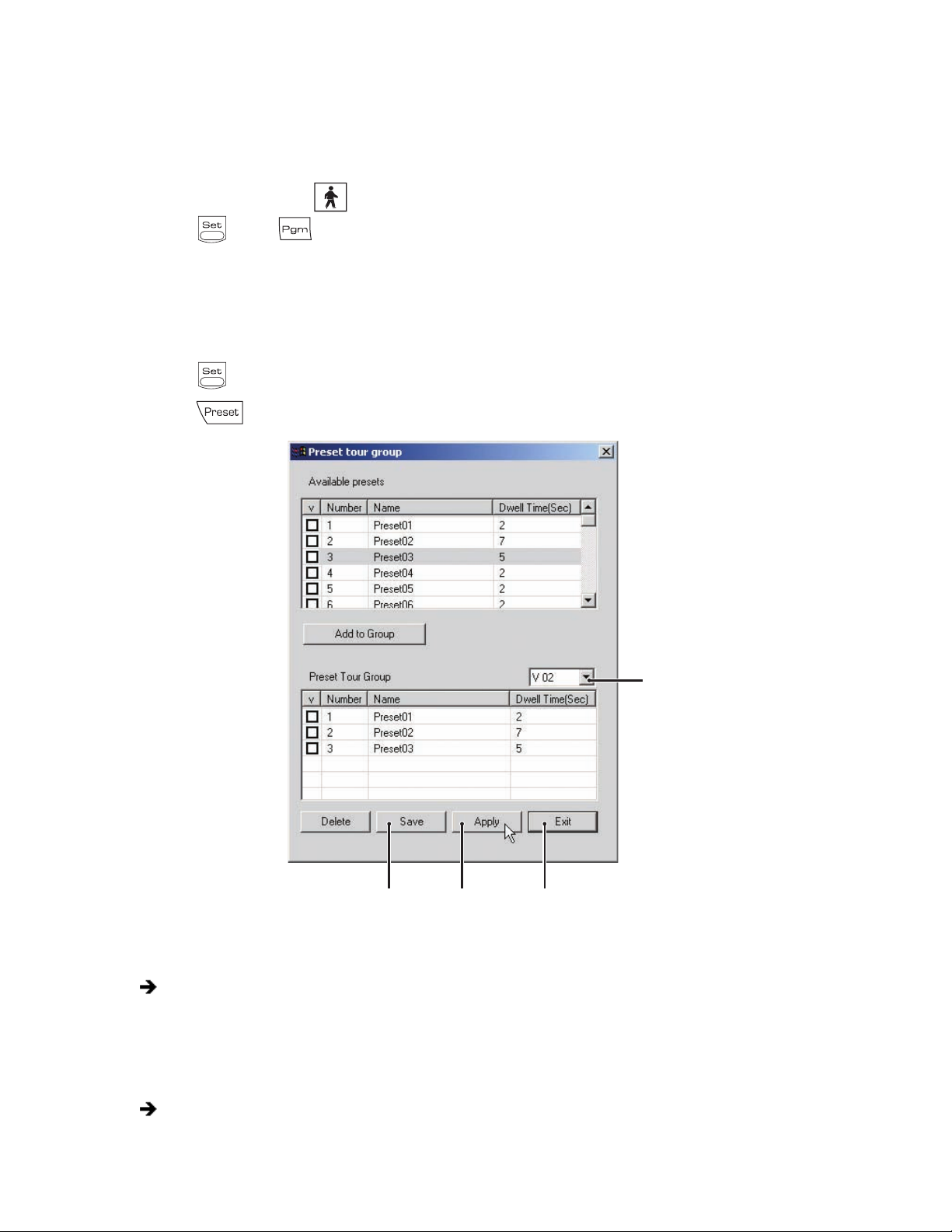
ACTIVATING A PRESET TOUR
This section describes how to activate a preset tour. You can save a preset tour for later use without engaging the tour by not performing step 5
and continuing on to step 6 without clicking Apply.
To activate a preset tour:
1. On the DX8000 toolbar, click .
2. Click and then to bring up the preset tour dialog box.
3. From the drop-down box, select the preset tour (1-4) you want to activate.
4. Click Save.
5. Click Apply.
6. Click Exit to return to the main screen.
7. Click on the PTZ keypad to exit programming mode.
8. Click on the PTZ keypad to activate the tour.
Figure 34. Activating a Preset Tour
To reactivate the last preset tour you configured:
On the keypad, click Preset.
DEACTIVATING A PRESET TOUR
To deactivate a preset tour, do one of the following:
• Use the mouse to move the on-screen PTZ control.
• Activate a PTZ preset.
58 C624M-C (5/06)
Page 59

USING THE KBD300A KEYBOARD
The KBD300A allows you to operate certain DX8000 live view display functions and control camera PTZ operations from a keyboard rather than a
mouse.
When connected to the DX8000 server, the KBD300A supports two modes: the Standard mode and the Shift mode. The Shift mode is entered by
pressing the Shift button and is indicated by the lighting of the shift button LED. For information about how to operate the KBD300A, refer to the
KBD300A Universal Keyboard Installation/Operation manual.
This section describes the KBD300A operational features and is organized as follows:
• KBD300A Standard Mode Operational Features on page 59
• KBD300A Shift Mode Operational Features on page 60
For information about connecting the KBD300A to the DX8000, refer to the DX8000 Installation manual. For information about configuring
DX8000 data communication settings for the KBD300A, refer to Setting Up the KBD300A Keyboard on page 161.
KBD300A STANDARD MODE OPERATIONAL FEATURES
The KBD300A Standard mode allows you to control certain DX8000 operation features in the view pane from the keyboard.
This section describes the KBD300A Standard mode features/functions. The Standard mode is effective within the DX8000 view pane. You can
program camera presets and patterns, operate the camera PTZ features, and assign cameras to panes. For detailed information about how to
operate the KBD300A, refer to the KBD300A Universal Keyboard Installation/Operation manual. For information about configuring DX8000 data
communication settings for the KBD300A, refer to Setting Up the KBD300A Keyboard on page 161.
The following table describes the KBD300A Standard mode operational features specific for the DX8000 server.
Table R. KB300A Standard Operational Mode Features
Keyboard Control Action
Joystick Controls the camera’s PTZ operation.
Number + PRESET (short) Moves camera to the programmed preset position.
Number + PRESET (long) Programs the current camera position to the desired preset number.
Number + PATTERN (long) Starts the pattern record mode.
ACK Stops the pattern record mode.
Number + PATTERN Runs the desired pattern.
Number + AUX ON/AUX OFF Turns the specified auxiliary output on or off.
Number + MON Assigns the selected camera to the desired view pane. The active view pane is highlighted.
To place the KBD300A in the standard mode:
On the KBD300A keyboard, press the SHIFT button.
The LED indicator should be off.
C624M-C (5/06) 59
Page 60

KBD300A SHIFT MODE OPERATIONAL FEATURES
The KBD300A Shift mode allows you to control certain DX8000 operation features in the Site tree from the keyboard.
This section describes the KBD300A Shift mode features/functions. The Shift mode is effective within the DX8000 Site tree. You can move the
cursor to select elements within the Site tree, expand/collapse elements, and select the display division. For detailed information about how to
operate the KBD300A, refer to KBD300A Universal Keyboard Installation/Operation manual. For information about configuring DX8000 data
communication settings for the KBD300A, refer to Setting Up the KBD300A Keyboard on page 161.
The following table describes the KBD300A Shift mode operational features specific to the DX8000 server.
Table S. KBD300A Shift Mode Operational Features
Keyboard Control Action
Joystick Activity within the DX8000 Site tree:
• Up/down direction: Moves the cursor vertically through each element in the Site tree.
An element is a DX8000 site, camera within each DX8000 site, or Alarm, ATM/POS, and relay within each
DX8000 site.
If an element is expanded, the joystick moves the cursor vertically through the objects of that element.
• Left/right direction:
– Right: Expands an element to display objects contained under the element.
– Left: Collapses an element and hides its objects. Select a camera/unit at the tree.
Number + CAM Expands the Site tree and selects the first camera in each DX8000 site. For example, if there are two sites with one
named DX8000 site 1 and the other named DX8000 site 2:
• Pressing 1 + CAM expands the Site tree for DX8000 site 1 and selects the first camera. But it does not assign
the selected camera to a view pane or display video.
• Pressing 2 + CAM expands the Site tree for DX8000 site 2 and selects the first camera. But it does not assign
the selected camera to a view pane or display video.
F2, F3, ON, OFF Cameras are assigned numerically 1–16 to the respectively number video. These controls display DX8000 video in
the following divisions:
• F2/OFF: Single-division view
• F3/MOM: 4-division view
• AUX ON: 9-division view
• AUX OFF: 16-division view
To place the KBD300A in the shift mode:
On the KBD300A keyboard, press the SHIFT button.
The LED indicator should be on.
60 C624M-C (5/06)
Page 61

Working in Playback Mode
Recorded video can be played back one channel at a time on the DX8000. Like live video, recorded video is viewed from the camera view panels
on the main screen. Refer to Understanding View Panes and Panels on page 26 for information on view panels. Only users with Standard User
access and higher are allowed to view recorded video.
This section describes how use the Playback mode and includes the following topics:
• Accessing Playback Mode on page 61
• Assigning Cameras to View Panels on page 61
• Playback On-Screen Display (OSD) on page 61
• Playback Controls on page 62
• Playback Timeline on page 64
• Playing Back Video by Time on page 65
• Playing Back Video by Event on page 66
• Operating Playback Digital Zoom on page 67
• Viewing Video in the Deinterlaced Mode on page 90
• Viewing Live and Playback Video Simultaneously on page 90
ACCESSING PLAYBACK MODE
To access the Playback mode:
On the DX8000 toolbar, click Live.
ASSIGNING CAMERAS TO VIEW PANELS
To assign a camera to a view panel:
1. Drag a camera from the Site tree onto a camera view pane.
2. Repeat this process for up to 36 cameras.
PLAYBACK ON-SCREEN DISPLAY (OSD)
The on-screen display for playback is identical to live view with the exception of a date/time field in place of the PTZ designator.
Figure 35. Playback OSD
C624M-C (5/06) 61
Page 62

PLAYBACK CONTROLS
Use the playback controls to start playback, control direction, and adjust speed. Click at any time to return to live view.
The playback controls are hidden in the extended view mode. In this case, select the standard view mode to display the playback controls.
To switch between the standard and extended view mode:
From the DX8000 menu bar, choose View > Extended View.
The following figure shows the DX8000 playback controls.
Figure 36. Playback Controls
The following table describes the parts of the payback controls.
Table T. Parts of the Playback Controls
Item Part Description
Frame-By-Frame
Reverse
Frame-By-Frame
Forward
Fast Forward to
End
Play Forward Initiates normal playback of recorded video in the forward direction.
Stop Stops playback control activity and returns to the Live View mode.
Each frame is displayed in reverse with each click of the Frame-by-Frame Reverse button.
Each frame is displayed in the forward direction with each click of the Frame-by-Frame Forward button.
Advances the bookmark to the end of the latest recorded video.
Pause Pauses video playback in the forward or reverse direction.
Play Reverse Initiates normal playback of recorded video in the reverse direction.
Rewind to
Beginning
62 C624M-C (5/06)
Returns the bookmark to the start of the earliest recorded video.
Page 63
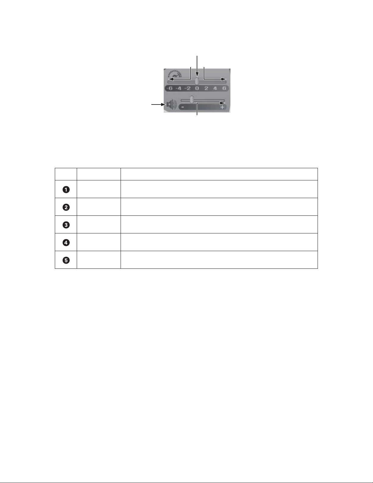
The following figure shows the DX8000 playback speed and volume controls.
Figure 37. Playback Speed and Volume Controls
The following table describes the parts of the playback speed and volume controls.
Table U. Parts of the Playback Speed and Volume Controls
Item Part Description
Normal Playback speed is at normal rate.
Faster Playback speed is increased to a faster rate.
Slower Playback speed is reduced to a slower rate.
Louder Volume is increased to a higher level or decreased to a lower level.
Mute Volume is silenced.
C624M-C (5/06) 63
Page 64

PLAYBACK TIMELINE
The playback timeline is used to select a day and time to begin playback. The timeline includes a horizontal slider that can be moved to select
playback time over a 24-hour period. Time periods containing recorded video are represented as color-coded segments of the timeline. The
following figure illustrates the timeline color-coding scheme.
Panel: 1/8 S03 C09 [Camera 9] 11-27-2003 05 00 56
00 01 02 03 04 05 06 07 08 09 10 11 12 13 14 15 16 17 18 19 20 21 22 23
The following table describes the parts of the playback timeline control.
Item Part Item Part
Currently displayed view panel Selected second
Total number of view windows Increase timeline detail
Site number Decrease timeline detail
Figure 38. Playback Timeline
Table V. Parts of the Playback Timeline Control
Camera number Alarm recording
Camera name Normal recording
Selected date Motion detection recording
Selected hour Timeline slider
Selected minute Instant recording
64 C624M-C (5/06)
Page 65

PLAYING BACK VIDEO BY TIME
This section describes how to play back video by time. The time is displayed in 24-hour clock format. You can select the time by moving the slider
along the timeline.
This section includes the following topics:
• Starting Playback from a Specific Point in Time on page 65
• Understanding Instant Playback on page 65
STARTING PLAYBACK FROM A SPECIFIC POINT IN TIME
To start video playback from a particular point in time:
1. On the DX8000 toolbar, click .
2. Select a camera by clicking it in the Site tree. You can also select the camera from a view pane if the camera appears in the panel.
3. In the Timeline section, do the following:
a. In the Date Selection drop-down box, select the day that you want playback to begin.
b. Use the spinner buttons to select the time.
4. Click to begin viewing.
Figure 39. Date Selection Drop-down Box
UNDERSTANDING INSTANT PLAYBACK
The DX8000’s ability to perform instant playback of video is limited by a one-minute delay interval. The DX8000 has a built-in latency of
approximately one minute between the time that video is captured and when it is written to the hard disk. This delay exists to ensure that video
is accurately stored and that the DVR’s database is updated correctly.
The delay interval is not affected if the DX8000 is in the alarm or motion record mode. In this case, the pre-alarm or pre-motion time period does
not become a factor in determining the delay interval.
To initiate an instant playback:
On the playback control, click Instant Playback. The timeline is zoomed to the last two to three minutes of data.
The user has the ability to view video that is just recorded. This video image resides in memory and has not yet been stored on the hard drive.
The color of the timeline will be green. This is because the system cannot tell what the data characteristic is while the data resides in memory
For example, if this data is recorded from a camera configured to monitor motion, and there is no motion activity, the data will not be stored on
the hard disk drive.
C624M-C (5/06) 65
Page 66

PLAYING BACK VIDEO BY EVENT
Users with Standard User access and higher can search video by events, such as motion detection or alarm activation. A sensor event is identical
to an alarm event.
To play back video recorded during an alarm or motion event:
1. On the DX8000 toolbar, click .
2. From the DX8000 menu bar, choose View > Index View. The Event Type drop-down box is displayed.
3. Select a camera by clicking it in the Site tree.
Figure 40. Event Type Drop-down Box
4. In the Event Type drop-down box, select the day that you want playback to begin.
5. In the Event Type drop-down box, select the event type you want to view. Options are as follows:
•All
•None
•Motion
• Alarm in
•ATM/POS
• Video Loss
6. Select an event from the listing.
7. On the playback control, click to begin viewing.
66 C624M-C (5/06)
Page 67

OPERATING PLAYBACK DIGITAL ZOOM
Video playback can be zoomed using a control keypad or the mouse when the DX8000 is in the Playback or Search mode. In Playback mode, the
on-screen PTZ feature is replaced with the mouse-activated digital zoom. Playback digital zoom is also available in Search mode. For information
on the Playback mode, refer to Working in Playback Mode on page 61. For information on the Search mode, refer to Working in Search Mode on
page 70.
The PTZ controls are hidden in the extended view mode. In this case, select the standard view mode to display the PTZ controls.
To switch between the standard and extended view mode:
From the DX8000 menu bar, choose View > Extended View.
This section describes how to operate playback digital zoom, and includes the following topics:
• Zoom Using the Digital Zoom Control on page 67
• Zoom Using the Mouse on page 68
• Panning a Zoomed Image on page 69
• Working in Playback Mode on page 61
• Working in Search Mode on page 70
ZOOM USING THE DIGITAL ZOOM CONTROL
The digital zoom feature is accessible when the DX8000 is in the Playback or Search mode. For information on the Playback mode, refer to
Working in Playback Mode on page 61. For information on the Search mode, refer to Working in Search Mode on page 70.
To zoom using the digital zoom control:
1. To place the DX8000 in the Playback or Search mode, do one of the following:
• On the DX8000 toolbar, click Live.
• On the DX8000 toolbar, click Search.
2. Click to start video playback.
3. Use the Digital Zoom control to zoom and pan video playback.
Figure 41. Playback Digital Zoom Control
C624M-C (5/06) 67
Page 68

Table W. Parts of the Digital Zoom Control
Item Part Description
Zoom In Allows you to magnify the entire pane. Click the Zoom In button to magnify to the next preset magnification
level (x1–6).
Zoom Out Allows you to reduce to the previous preset magnification. Click the Zoom Out button to reduce to the
previous magnification level.
Pan Left Allows you to move the magnified playback image to the left.
Pan Right Allows you to move the magnified playback image to the right.
Pan Up Allows you to move the magnified playback image up.
Pan Down Allows you to move the magnified playback image down.
Zoom Restore Allows you to return the zoomed image to the original size.
ZOOM USING THE MOUSE
The following table describes the parts of the Digital Zoom control.
The DX8000 allows you to use the mouse to drag a selection region (rectangle) around a specific area of a pane to zoom in and out. A small
rectangle about 0.25 inches (6.4 mm) square provides a x6 zoom factor. As the selection area increases in size, the zoom in/out factor decreases:
x5, x4, x3, x2, and x1.
• If you use the mouse to select an area about 0.25 inches (6.4 mm) in size, the zoom feature performs as follows:
– If zooming in, the zoom factor is at x6. In this case, the selected viewing area is zoomed to the largest size.
– If zooming out, the zoom factor is at x6. In this case, the selected viewing area is zoomed to the original size.
• If you use the mouse to select the entire pane, the zoom feature performs as follows:
– If zooming in, the zoom factor is at x1. In this case, the selected viewing area is slightly enlarged. You would have to perform many
zoom in operations to arrive at the largest zoom size.
– If zooming out, the zoom factor is at x1. In this case, the selected viewing area is slightly reduced. You would have to perform many
zoom out operations to arrive at the original size.
• You can also use the hand tool and the mouse scroll wheel to zoom in and out.
The zoom factor is displayed in the upper-right corner of the pane. The effective zoom in factor is displayed after the zoom operation is
performed. The effective zoom out factor is not displayed.
To zoom using the mouse:
1. To place the DX8000 in the Playback or Search mode, do one of the following:
• On the DX8000 toolbar, click Live.
• On the DX8000 toolbar, click Search.
2. Click to start video playback.
3. Do the following:
a. To zoom in, click and drag the mouse diagonally in a downward direction to your right.
68 C624M-C (5/06)
Page 69

.
Figure 42. Zoom In Using Mouse
b. To zoom out, click and drag the mouse diagonally in an upward direction to your left.
Figure 43. Zoom Out Using Mouse
PANNING A ZOOMED IMAGE
This section describes how to use the hand tool and mouse wheel to zoom in and out.
To pan a zoomed portion of video within the view panel:
1. To place the DX8000 in the Playback or Search mode, do one of the following:
• On the DX8000 toolbar, click Live.
• On the DX8000 toolbar, click Search.
2. Right-click within the view panel. The mouse pointer now resembles a hand.
3. Click and drag the mouse using the left mouse button in the direction you want to move the video image.
4. Right-click again to return to zoom mode.
Figure 44. Panning Zoomed Video with the Mouse
C624M-C (5/06) 69
Page 70

Working in Search Mode
The DX8000 Series DVR supports four video search methods: index, thumbnail, POS, and pixel. For information about the user access level
required to search video data, refer to Definition of User Access Levels on page 173.
To enter the Search mode:
On the DX8000 toolbar, click Search.
This section describes how to use the Search mode and includes the following topics:
• Search Window on page 71
• Displaying a Deinterlaced Image in the Search Mode on page 73
• Index Video Search on page 73
• Thumbnail Video Search on page 74
• POS Search on page 76
• Pixel Video Search on page 87
• Working with Special View and Search Methods on page 90
70 C624M-C (5/06)
Page 71

SEARCH WINDOW
The search window facilitates access to the search capabilities of the DX8000. Available search methods include index, thumbnail, and pixel.
Each search method allows users with Standard User access and higher to locate video data instantly using criteria such as time of day or
changes in window pixels.
As in Playback mode, digital zoom, export, and print features are available in Search mode. For more information, refer to Operating Playback
Digital Zoom on page 67, Exporting Video on page 91, and Printing Images on page 101.
The following figure shows the parts of the DX8000 window in the Search mode.
Figure 45. DX8000 DVR Search Mode Window
C624M-C (5/06) 71
Page 72

The following table describes the parts of the DX8000 window in the Search mode.
Table X. Parts of the DX8000 Window in Search Mode
Item Part Description
Index Search Allows users to search motion and alarm events listed in the event index panel.
Thumbnail Search Allows users to visually search video that has been recorded over a 24-hour period. Video is presented as a
series of thumbnail images. Each thumbnail represents the first image recorded during a specified period of
time. Thumbnails can be expanded and collapsed to represent hourly, 10-minute, and 1-minute intervals.
POS Search Allows users to search ATM/POS transaction text data.
Pixel Search Allows users to search any 24-hour period of recorded video automatically for changes in screen pixels.
View Window Displays search video, image thumbnails, and pixel grid.
Site tree Facilitates top-down, hierarchical management of DX8000 resources, such as servers, cameras, alarms, and
relays.
Event Index Panel Lists motion and alarm events over the 24-hour time period specified in the playback timeline.
Select All Check Box Enables playback for all visible view panels when selected. If this check box is deselected, only the selected
channel will play. This control is only available while using Index Search.
Playback Timeline Displays a 24-hour timeline marked with color-coded video events. Allows user to select a date and time for
playback.
Playback Control Panel Provides buttons to control video playback. Includes forward and reverse playback and still image. Also
provides controls for playback speed and volume.
Playback Zoom Control Provides access to digital zoom features during playback.
Search Control Provides access to the index, thumbnail, POS, and pixel search controls.
72 C624M-C (5/06)
Page 73
DISPLAYING A DEINTERLACED IMAGE IN THE SEARCH MODE
If you are searching for an image that is recorded at 4CIF at a low frame rate per second, the viewed image might move or tear. The View menu’s
Deinterlaced Image option is used to enhance the image during a search activity.
To search video using the deinterlaced option:
1. On the menu bar, click View > Display deinterlaced image.
2. On the DX8000 toolbar, click . The DX8000 is placed in the Search mode.
INDEX VIDEO SEARCH
Index search allows a user to search video by events, such as motion detection or alarm activation. Events are listed chronologically and by type.
To ensure that the proper camera channel is selected, check the camera information box above the playback timeline or verify that the desired
view panel is framed with a thin red outline.
To search video by motion or alarm events:
1. On the DX8000 toolbar, click .
2. On the DX8000 Search control, click .
3. On the DX8000 toolbar, click a view panel division button.
4. From the Site tree, drag the camera channel you want to search onto one of the view panels.
5. Click the view panel of the channel you want to search.
6. From the drop-down box on the playback timeline, select the day you want playback to begin.
7. Select the event type you want to view from the event type drop-down box.
Only events recorded for the selected camera are listed in the index. A sensor event is identical to an alarm event. Options are as follows:
•All
•None
•Motion
• Alarm in
•ATM/POS
• Video Loss
8. Select an event from the index.
9. Verify that the “Select all” check box is selected. Deselecting the “Select all” check box will disable playback for all view panels except the
channel being searched.
The DX8000 allows you to view playback on multiple cameras in addition to the camera being searched. This feature is valuable if you want
to examine a variety of views recorded at the time a certain event was detected.
10. Click to begin viewing.
C624M-C (5/06) 73
Page 74
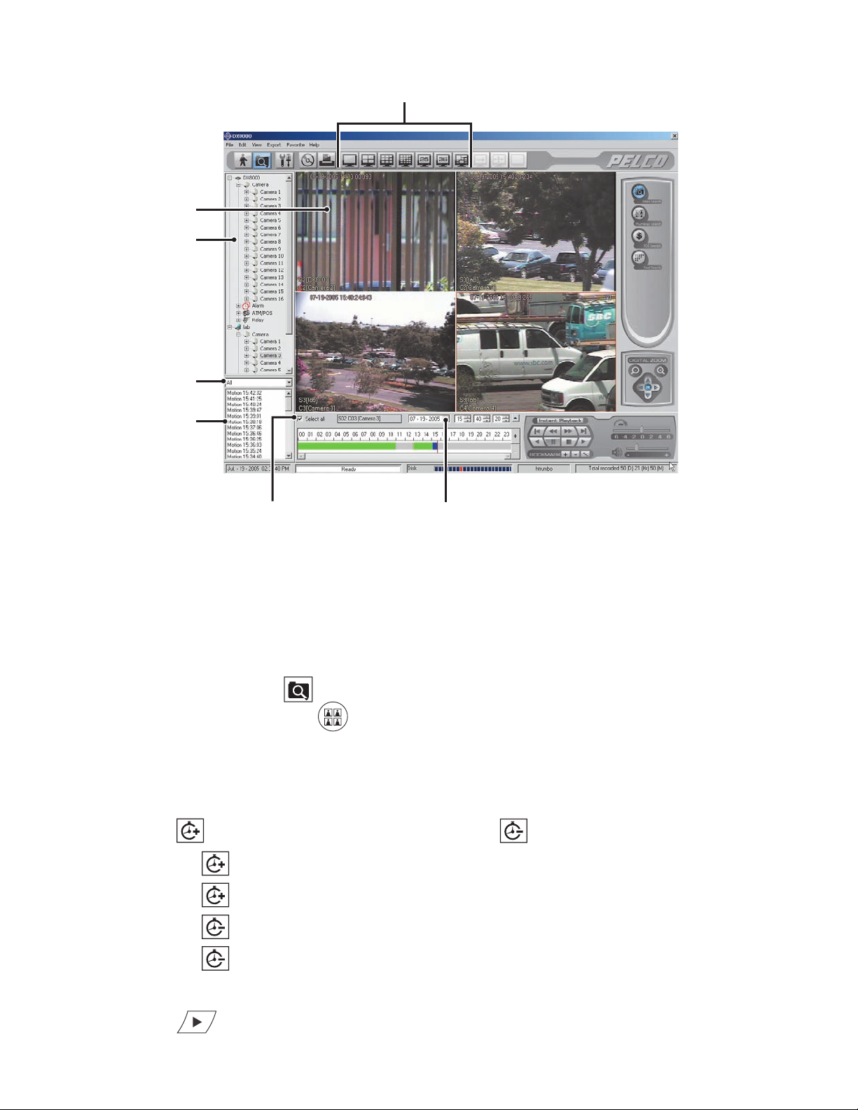
THUMBNAIL VIDEO SEARCH
Thumbnail search allows users to visually search video that has been recorded over a 24-hour period. Video is presented as a series of thumbnail
images. Each thumbnail represents the first image recorded during a specified period of time. Thumbnails can be expanded and collapsed to
represent hourly, 10-minute, and 1-minute intervals.
To search video visually using thumbnail images:
1. On the DX8000 toolbar, click .
2. On the DX8000 Search control, click .
3. Select a camera from the Site tree.
4. From the drop-down box, select the date on which you want to begin your search.
5. Click the thumbnail for the hour you want to begin searching.
6. Click to change the thumbnail time range to shorter intervals, or click to change the thumbnail time range to longer intervals.
• Click to change from 1-hour intervals to 10-minute intervals.
• Click again to change from 10-minute intervals to 1-minute intervals.
Figure 46. DX8000 DVR Index Search Screen
• Click once to change from 1-minute intervals to 10-minute intervals.
• Click again to change from 10-minute intervals to 1-hour intervals.
7. Click the thumbnail of the interval you want to search.
8. Click to view video.
74 C624M-C (5/06)
Page 75
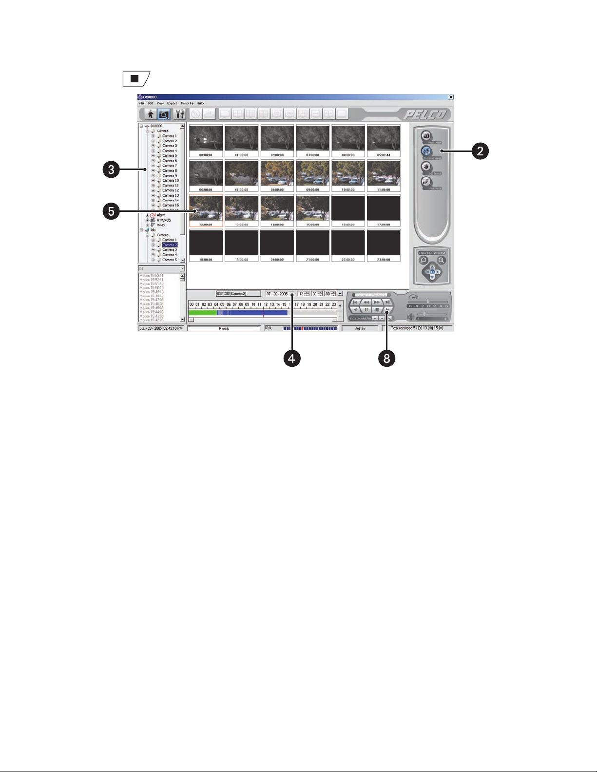
Double-clicking a thumbnail image will enlarge the image and begin playback.
9. Click to return to thumbnail images.
Figure 47. DX8000 DVR Thumbnail Search Screen
C624M-C (5/06) 75
Page 76

POS SEARCH
The DX8000 allows a user to search any 24-hour period of recorded POS video and data. To record ATM/POS video and data, the ATM/POS
devices and DX8000 must first be connected and configured as follows:
• Physically connect the ATM/POS devices to the DX8000.
• Set up camera-to-ATM/POS device linking.
• Configure the DX8000 ATM/POS settings for each attached ATM/POS device.
• Start an ATM/POS transmittal and verify that the DX8000 is receiving the ATM/POS video and data.
For information about setting up the DX8000 for ATM/POS applications, refer to the following sections:
• Linking Relay Outputs to ATM/POS Events on page 114
• Linking Cameras to Record in Response to ATM/POS Events on page 117
• Linking Presets and Patterns to ATM/POS Events on page 120
• Setting Up ATM/POS Device Communication Ports on page 149
• Setting UP ATM/POS Device Properties on page 150
This section describes how to use the POS search feature and includes the following topics:
• Understanding the POS Search View on page 77
• Searching and Displaying POS Data by Device Name on page 80
• Searching by POS Transaction Number on page 82
• Searching for All Transactions with Exceptions on page 83
• Searching for Transactions that Satisfy Specific Exceptions on page 84
• Searching for Transactions by Line Item on page 85
• Searching for Transactions by Action Code on page 86
76 C624M-C (5/06)
Page 77
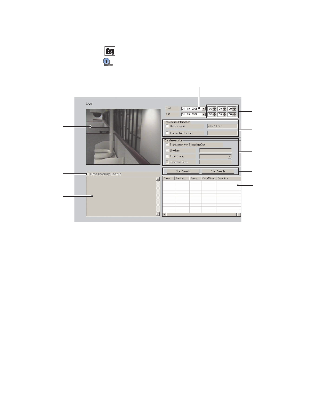
UNDERSTANDING THE POS SEARCH VIEW
To enter the POS Search mode:
1. On the DX8000 toolbar, click .
2. On the Search control, click . The POS search view is displayed.
The following figure shows the parts of the POS search view.
Figure 48. POS Search View
C624M-C (5/06) 77
Page 78
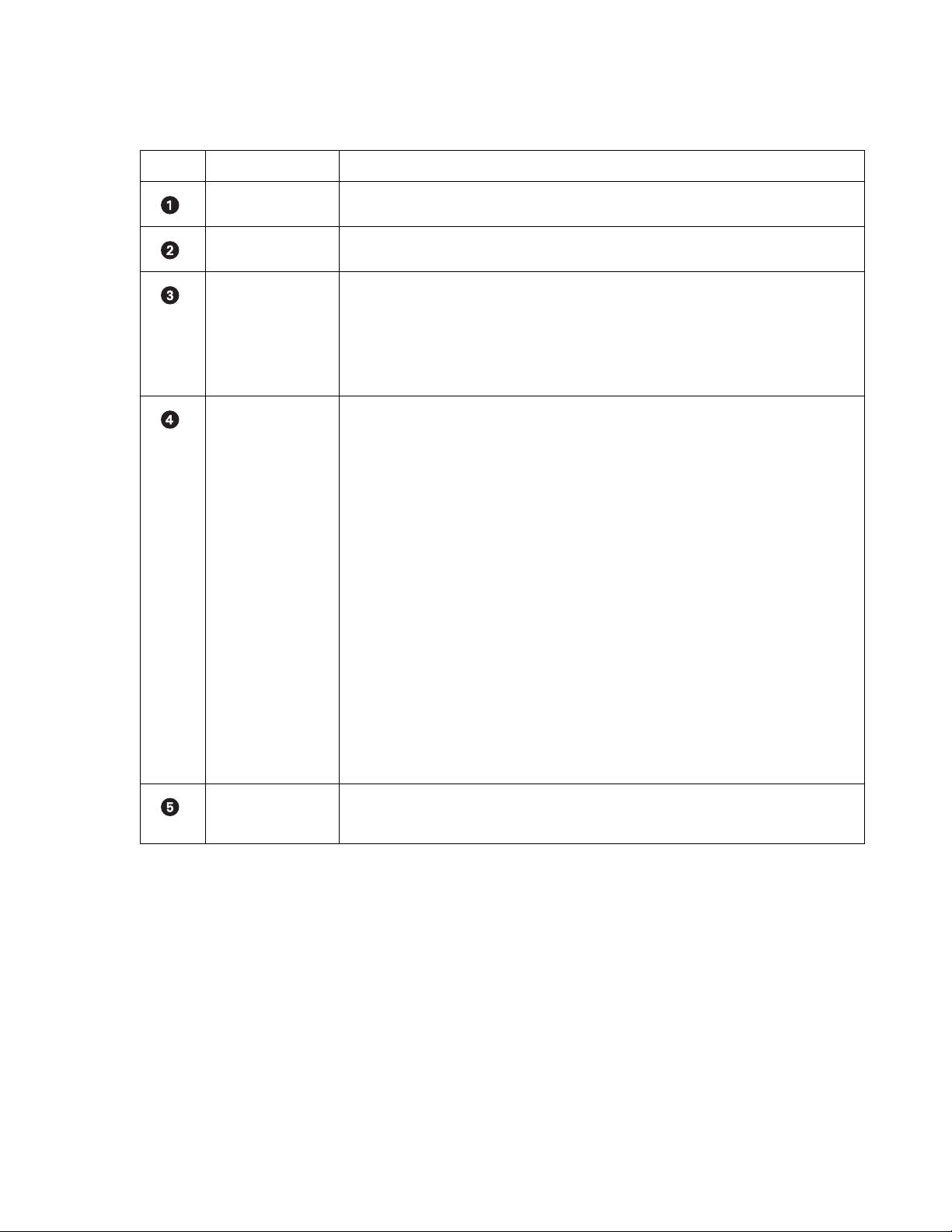
The following table describes the parts of the POS search view.
Table Y. Parts of the POS Search View
Item Part Description
Date Date range for which to search the video and data.
Time Time range based on a 24-hour time period for searching POS events.
Tr an sa ct io n
Information
Allows POS search by transaction information options as follows:
• Device Name: The ATM/POS device linked to a specific camera. In this case, selecting a
camera linked to an ATM/POS device automatically inserts the name of the ATM/POS device in
the Device Name box.
• Transaction Number: A number assigned by the ATM/POS device that is printed on the sales
are transaction receipt.
Data Information Allows POS search by data information options as follows:
• Transaction with Exception Only: Finds all transactions for which an exception is defined.
• Line Item: Allows you to search POS data by a specific transaction line item, based on the
following guidelines:
– Line item entries are not case sensitive. Enter lower or uppercase characters.
– Specify the asterisk (*) wildcard.
– Search by a single word or multiple words appearing in a transaction line.
– Enter the first few characters of the first word appearing in the transaction and the
wildcard. As an example, for a line item containing the entry “small orange juice,” enter
sma*. The search returns all transactions that contain the word “small.”
– Enter the first few characters of the second word in a transaction and the wildcard. As an
example, for a line item containing the entry “small orange juice,” enter: ora*. The search
returns all transactions that contain the word “orange.”
– Search by abbreviation. An example, for a line item containing the entry “Soda 6-pk,” enter
6-pk. The search returns all transactions that contain the abbreviation “6-pk.”
• Action Code: A two-letter abbreviation designating a specific action code. For information
about action codes, refer to Setting UP ATM/POS Device Properties on page 150.
• Exception Code: A predefined transaction filter used to detect a specific data structure within
the ATM/POS transaction data. For information about exceptions, refer to Setting Up ATM/POS
Exceptions on page 155.
Start and Stop Start: Initiates a search event.
Stop: Ends a search event.
78 C624M-C (5/06)
Page 79
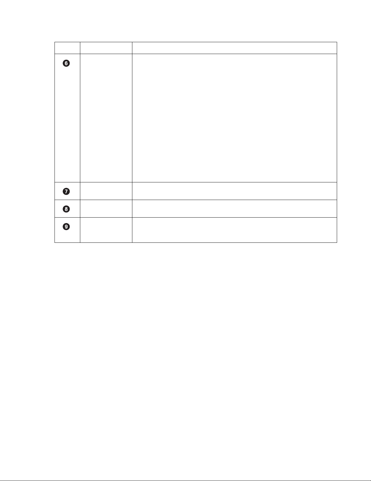
Table Y. Parts of the POS Search View (Continued)
Item Part Description
POS Search Table Lists the data discovered in response to the POS options selected for the transaction and data
information.
• Channel Number: From 1–16.
• Device Name: By default, ATM/POS01 to ATM/POS16. The device name can be changed.
• Transaction Number: Number assigned by the ATM/POS device to the transaction data.
• Date/Time: Date and time transaction is recorded.
• Exception: Yes if an exception filter is active for the transaction data has an exception. No if
the transaction does not have an exception filter.
The transaction and data information are based on the ATM/POS configuration settings derived from
the following:
• Data format
• ATM/POS exceptions
• Exception action codes
For information about setting up ATM/POS transaction and data options, refer to Setting UP ATM/
POS Device Properties on page 150.
Data Window Area where recorded transaction data is displayed.
Data Overlay Box The function is not supported at this time.
Video Window Area where live and playback (recorded) video is viewed. Playback video is started at the date and
time specified for the respective transaction data as shown in the POS Search table. The DX8000
playback controls are used to view playback video.
C624M-C (5/06) 79
Page 80

SEARCHING AND DISPLAYING POS DATA BY DEVICE NAME
4c
4
b
4a
4
d
You can perform a general search for POS transaction data record for a particular ATM/POS device and its associated camera. Use the date and
time, and ATM/POS device name as the search criteria. The search results contain all POS transactions recorded for that device according to the
specified date and time.
Searching POS Data by Device Name
To search POS transaction data by ATM/POS device name:
1. On the DX8000 toolbar, click .
2. On the Search control, click . The POS search view is displayed.
3. To select a channel, in the DX8000 Site tree, click a camera that is linked to an ATM/POS device.
By default, the name of the ATM/POS device linked to the selected camera/channel is displayed in the Device Name text box. In this case,
the Device Name text box is deselected.
4. Select the date and time for the POS search event as follows:
a. Select the Start date.
b. Select the End date.
c. Select the End time.
d. Select the Start time.
5. In the Transaction Information section, click the check box to select Device Name. The Device Name text box is available.
6. Verify that the ATM/POS device name displayed in the Device Name text box is the correct device for the search.
7. Click Start Search. The POS Search Table is populated with POS transaction data.
4a
4c
Figure 49. POS Transaction Search by Device Name
80 C624M-C (5/06)
Page 81

Displaying POS Data Discovered by Device Name
To display a POS transaction and its associated video:
1. On the DX8000 toolbar, click .
2. On the Search control, click . The POS search view is displayed.
3. Perform a POS search by device name. For information about performing a search by ATM/POS device name, refer to Searching POS Data
by Device Name on page 80.
4. In the POS Search Table, click a transaction. The transaction data is displayed in the Data window.
5. On the playback control, click Play. The video recorded for the selected POS transaction is played back and is displayed in the Video
window.
6. Use the playback control to stop or pause playback, reverse playback, and so forth.
Figure 50. Display a POS Transaction Search by Device Name
C624M-C (5/06) 81
Page 82

SEARCHING BY POS TRANSACTION NUMBER
3
b
The DX8000 allows you to search for a POS event by transaction number. In this case, you must specify the channel, date, and a time window in
which the transaction is recorded.
To search for an POS event by transaction number:
1. On the DX8000 toolbar, click .
2. On the Search control, click . The POS search view is displayed.
3. To select a device name, do one of the following:
• In the DX8000 Site tree, click a camera that is linked to an ATM/POS device.
By default, the name of the ATM/POS device linked to the selected camera/channel is displayed in the Device Name text box. In this
case, the Device Name text box is deselected.
• Do the following:
(1) In the Transaction Information section, click the check box to select Device Name. The Device Name text box is available.
(2) Type the ATM/POS device name in the Device Name text box.
4. Select the date and time that you want to search for the transaction number.
5. In the Transaction Information section, click the check box to select Transaction Number. The Transaction Number text box is available.
6. In the Transaction Number text box, type the transaction number.
7. Click Start Search. If the channel, date, time, and transaction number are valid, the POS transaction is displayed in the POS Search Table.
8. In the POS Search Table, click a transaction entry. The transaction data is displayed in the Data window.
9. On the playback controls, click Forward Playback. The video recorded for the transaction is displayed in the Video window.
Figure 51. Searching an POS Event by Transaction Number
82 C624M-C (5/06)
Page 83

SEARCHING FOR ALL TRANSACTIONS WITH EXCEPTIONS
3
b
The DX8000 allows you to search for transactions that meet conditions defined by one or more exceptions. In this case, you must configure your
search criteria based on the following:
• Channel: Camera that captured the video and is linked to the ATM/POS device that produced the transaction data.
• Date/time: Date and time window within which the transactions were recorded.
To use an exception to search transaction data, the exception must be created first, before recording the transaction data. If the transaction data
is recorded before the exception filter is defined, the exception filter will not find the data structure within the transaction data.
To search for only POS events by transaction with exception:
1. On the DX8000 toolbar, click .
2. On the Search control, click . The POS search view is displayed.
3. To select a ATM/POS device, do one of the following:
• In the DX8000 Site tree, click a camera that is linked to the ATM/POS device.
By default, the name of the ATM/POS device linked to the selected camera/channel is displayed in the Device Name text box. In this
case, the Device Name text box is deselected.
• Do the following:
(1) In the Transaction Information section, click check box to select Device Name. The Device Name text box is available.
(2) Type the ATM/POS device name in the Device Name text box.
4. Set the date and time range for the search.
5. In the Data Information section, click check box to select Transaction with Exception Only. The Exception Code check box is available.
6. Click Start Search. If the device name/channel, date, and time are valid, and if transactions with exceptions were recorded during the time
range, the transactions are displayed in the POS Search Table.
7. In the POS Search Table, click a transaction. The transaction data is displayed in the Data window.
8. On the playback controls, click Forward Playback. The video recorded for the transaction is displayed in the Video window.
Figure 52. Searching for Transaction with Exception Only Events
C624M-C (5/06) 83
Page 84

SEARCHING FOR TRANSACTIONS THAT SATISFY SPECIFIC EXCEPTIONS
3
b
The DX8000 allows you to search for and display ATM/POS transactions that meet conditions as defined by one or more exceptions. You can use
specific exception codes to define the search criteria. To use an exception to search transaction data, the exception must be created first, before
recording the transaction data. If the transaction data is recorded before the exception filter is defined, the exception filter will not find the data
structure within the transaction data.
The search criteria is based on the following:
• Channel: Camera that captured the video and is linked to the ATM/POS device that produced the transaction data.
• Date/time: Date and time window within which the transactions were recorded.
• Exception code: Predefined transaction filter used to detect a specific data structure within the ATM/POS transaction data.
To search for transactions that meet specific exceptions:
1. On the DX8000 toolbar, click .
2. On the Search control, click . The POS search view is displayed.
3. To select a ATM/POS device, do one of the following:
• In the DX8000 Site tree, click a camera that is linked to the ATM/POS device.
By default, the name of the ATM/POS device linked to the selected camera/channel is displayed in the Device Name text box. In this
case, the Device Name text box is deselected.
• Do the following:
(1) In the Transaction Information section, click the check box to select Device Name. The Device Name text box is available.
(2) Type the ATM/POS device name in the Device Name text box.
4. Set the date and time range for the search.
5. In the Data Information section, do the following:
a. Click the check box to select Transaction with Exception Only. The Exception Code check box is available.
b. Click the check box to select Exception Code. The Exception Code text box is available.
c. Type the exception code in the text box.
6. Click Start Search. If the device name/channel, date, and time are valid, and if transactions with exceptions were recorded during the time
range, the transactions are displayed in the POS Search Table.
7. In the POS Search Table, click a transaction. The transaction data is displayed in the Data window.
Figure 53. Transactions that Satisfy Specific Exception Filters
84 C624M-C (5/06)
Page 85

SEARCHING FOR TRANSACTIONS BY LINE ITEM
The DX8000 allows you to search for and display ATM/POS transactions that contain a unique line item. Use the asterisk (*) as a wildcard
character to substitute for zero or more characters.
The search criteria is based on the following:
• Channel: Camera that captured the video and is linked to the ATM/POS device that produced the transaction data.
• Date/time: Date and time window within which the transaction(s) were recorded.
• Line item: The line item has the following guidelines:
– Line item entries are not case sensitive. Enter lower or uppercase characters.
– Specify the asterisk (*) wildcard.
– Search by a single word or multiple words appearing in a transaction line.
– Enter the first few characters of the first word appearing in the transaction and the wildcard. As an example, for a line item containing
the entry “small orange juice,” enter sma*. The search returns all transactions that contain the word “small.”
– Enter the first few characters of the second word in a transaction and the wildcard. As an example, for a line item containing the entry
“small orange juice,” enter: ora*. The search returns all transactions that contain the word “orange.”
– Search by abbreviation. An an example, for a line item containing the entry “Soda 6-pk,” enter 6-pk. The search returns all transactions
that contain the abbreviation “6-pk.”
To search for transactions that contain a unique line item:
1. On the DX8000 toolbar, click .
2. On the Search control, click .The POS search view is displayed.
3. To select a ATM/POS device, do one of the following:
• In the DX8000 Site tree, click a camera that is linked to the ATM/POS device.
By default, the name of the ATM/POS device linked to the selected camera/channel is displayed in the Device Name text box. In this
case, the Device Name text box is deselected.
• Do the following:
(1) In the Transaction Information section, click the check box to select Device Name. The Device Name text box is available.
(2) Type the ATM/POS device name in the Device Name text box.
4. Set the date and time range for the search.
5. In the Data Information section, do the following:
a. Click the check box to select Line Item. The Line Item text box is available.
b. Type the name of the line item in the text box.
6. Click Start Search. If the device name/channel, date, and time are valid, transactions containing the line item are displayed in the POS
Search Table.
7. In the POS Search Table, click a transaction. The transaction data is displayed in the Data window.
C624M-C (5/06) 85
Page 86

3
b
5a
5b
5a
5b
Figure 54. Transactions that Contain a Unique Line Item
SEARCHING FOR TRANSACTIONS BY ACTION CODE
The DX8000 allows you to search for and display ATM/POS transactions by action code. To use an action code to search transaction data, the
action code must be created first, before recording the transaction data. If the transaction data is recorded before the action code is defined, the
action code will not find the data structure within the transaction data.
The search criteria is based on the following:
• Channel: Camera that captured the video and is linked to the ATM/POS device that produced the transaction data.
• Date/time: Date and time window within which the transaction(s) were recorded.
• Action code: Special two-character filter that defines a specific transaction event.
To search for transactions by action code:
1. On the DX8000 toolbar, click .
2. On the Search control, click . The POS search view is displayed.
3. To select a ATM/POS device, do one of the following:
a. In the DX8000 Site tree, click a camera that is linked to the ATM/POS device.
By default, the name of the ATM/POS device linked to the selected camera/channel is displayed in the Device Name text box. In this
case, the Device Name text box is deselected.
or
b. Do the following:
(1) In the Transaction Information section, click the check box to select Device Name. The Device Name text box is available.
(2) Type the ATM/POS device name in the Device Name text box.
4. Set the date and time range for the search.
5. In the Data Information section, do the following:
a. Click the check box to select Action Code. The Action Code drop-down box is available.
b. In the Action Code drop-down box, select an action code. For information about action codes, refer to Using Action Codes on
page 155.
86 C624M-C (5/06)
Page 87

6. Click Start Search. If the device name/channel, date, and time are valid, transactions containing the line item are displayed in the POS
3
b
5a
5b
Search Table.
7. In the POS Search Table, click a transaction. The transaction data is displayed in the Data window.
5a
5b
Figure 55. Searching Transactions by Action Code
PIXEL VIDEO SEARCH
The DX8000 allows a user to search any 24-hour period of recorded video automatically for changes in screen pixels. This feature can be
configured to identify motion events even when motion detection has not been enabled on a camera.
This section describes how to search video by changes in screen pixels and includes the following topics:
• Searching Video Based on Changes in Screen Pixels on page 87
• Viewing a Video Thumbnail on page 89
SEARCHING VIDEO BASED ON CHANGES IN SCREEN PIXELS
DX8000 pixel video search is accomplished in two steps:
• Searching recorded video for changes in screen pixels.
After the search has been completed, the DX8000 displays a series of thumbnails below the search grid. Each thumbnail contains the first
image of recorded video for the specified date and time range period.
NOTE: A pixel search might not detect obvious movement.
• Viewing the thumbnails.
For information on how to view the video thumbnail, refer to Viewing a Video Thumbnail on page 89.
To search video by analyzing changes in screen pixels:
1. On the DX8000 toolbar, click .
2. On the Search control, click .
3. Select a camera from the Site tree.
4. From the drop-down box, select the date on which you want to begin your search.
C624M-C (5/06) 87
Page 88

5. Select the start and end times to define your search range.
6. Using your mouse, highlight areas on the grid that you want to search for pixel changes.
• Hold down the left mouse button and drag to select areas.
• Hold down the right mouse button and drag to clear areas.
7. Adjust the pixel sensitivity threshold. Moving the slider to the left decreases sensitivity and moving it to the right increases sensitivity.)
8. Click Start and then wait for the progress line on the status bar to return to Ready.
9. Use the icon to show and hide the pixel grid for a clearer view in the search screen.
Figure 56. Pixel Search Screen
88 C624M-C (5/06)
Page 89

VIEWING A VIDEO THUMBNAIL
After the search has been completed, a series of thumbnails appear on the screen below the search grid. Each thumbnail contains the first image
of recorded video for the listed time period.
• Double-clicking a thumbnail will cause it to begin playing.
• Click and to move backwards and forwards through thumbnails.
To view a video thumbnail:
1. Click a thumbnail. The thumbnail’s search parameters (date and time) are displayed below the search grid. The thumbnail’s search start
time is a few seconds ahead of the search start time you entered.
Figure 57. Thumbnail Images Marking Pixel Changes
2. To locate playback at the start of the first image, click . The video scene is played back and displayed in reverse.
3. Click to pause the video play back when the beginning of the first recorded is reached.
4. Click . Playback starts and the video scene is displayed.
5. Click to remove the thumbnail results.
C624M-C (5/06) 89
Page 90

WORKING WITH SPECIAL VIEW AND SEARCH METHODS
The DX8000 allows you to do the following:
• View video in the deinterlaced mode.
• View live and playback video simultaneously.
• View and search backed-up video. You must use the DX8000 Client application to view and search backed-up video. For more information,
refer to the DX8000 Client Application Manual.
This section describes how to use special view and search methods and includes the following topics:
• Viewing Video in the Deinterlaced Mode on page 90
• Viewing Live and Playback Video Simultaneously on page 90
VIEWING VIDEO IN THE DEINTERLACED MODE
Images recorded at 4CIF at a low frame rate per second might move or tear. In this case, you can use the View menu’s Deinterlaced Image option
to enhance the displayed image. In the deinterlaced mode, the DX8000 converts the recorded image and displays it at 2CIF resolution. The
process removes one of the 4CIF interlaced fields (even or odd) from the 4CIF recorded image to arrive at 2CIF resolution for the displayed image.
The original image is retained at the recorded 4CIF resolution.
For exported images, the DX8000 provides a global option for enabling a deinterlacing filter. In this case, the selected channel’s image is
exported at 2CIF resolution. This setting is effective for all channels and cannot be set for individual channels. For more information about
enabling the denaturalizing filter, refer to Enabling the Deinterlacing Filter on page 94.
To view video using the deinterlaced option:
1. Click to start video playback.
2. On the menu bar, click View > Display deinterlaced image.
VIEWING LIVE AND PLAYBACK VIDEO SIMULTANEOUSLY
The DX8000 allows simultaneous viewing of live and playback video from a single camera source.
To view live and playback video from the same camera:
1. On the DX8000 toolbar, click .
2. Drag a camera from the Site tree to a view panel.
3. Click to begin playback.
4. Drag the same camera from the Site tree onto a different view panel while video is playing.
90 C624M-C (5/06)
Page 91
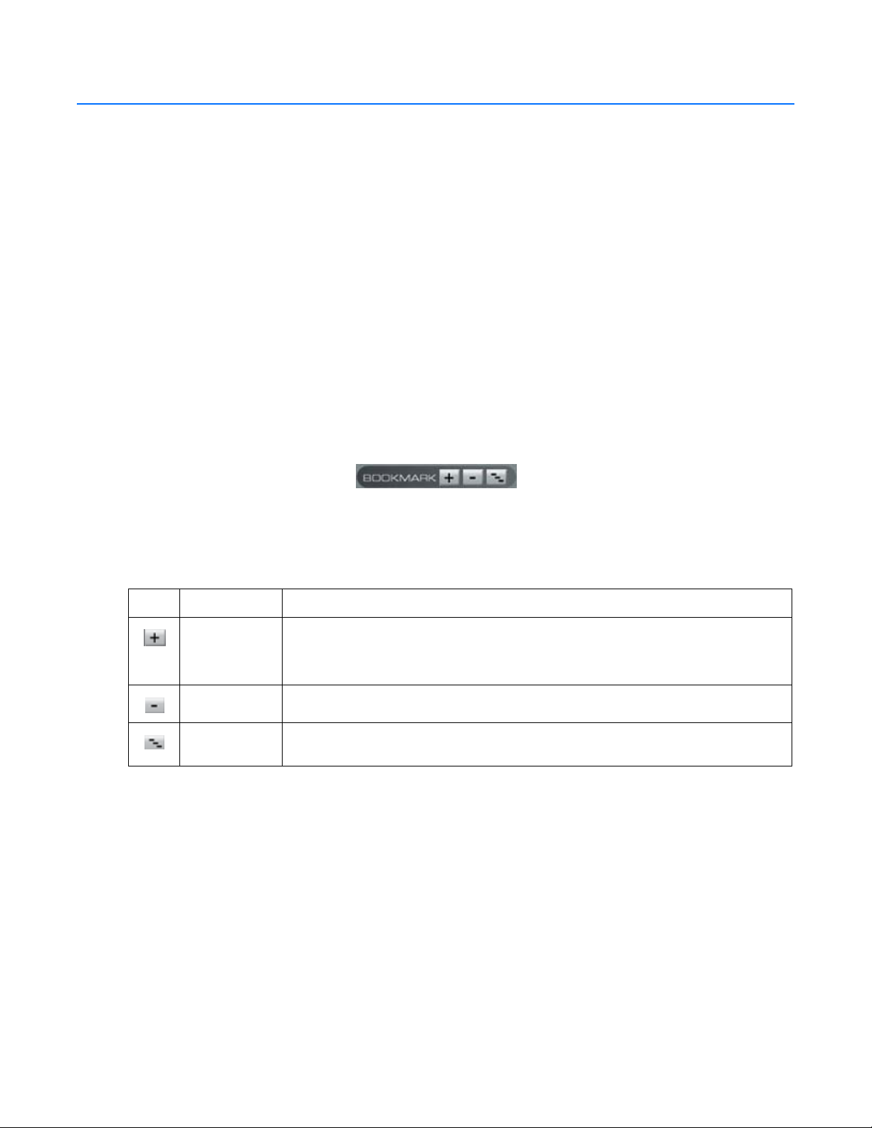
Exporting Video
Power Users and Administrators can export sections of prerecorded video to magnetic or optical media. The DX8000 must be in the Playback or
Search mode to export video. You cannot access Export in Live mode. To export video or still images to a CD-R/RW or DVD-R/RW, you must have
Nero® Express CD burning software version 6.3.1.25 installed on the DX8000 DVR.
This section describes how to export video and includes the following topics:
• Exporting Bookmarked Video Regions on page 91
• Inserting and Removing a USB Flash Drive on page 93
• Enabling the Deinterlacing Filter on page 94
• Mapping and Disconnecting a Network Drive on page 94
• Performing the Export on page 95
• Stopping an Export While in Process on page 100
EXPORTING BOOKMARKED VIDEO REGIONS
You can bookmark multiple regions of video along the timeline for export. Bookmarked regions are designated with start point and end point
bookmarks. Multiple regions can be bookmarked along a single 24-hour timeline, but only a single channel can be exported at a time.
Bookmarked regions are listed in the Export Video dialog box at the time of export.
The following figure shows the DX8000 bookmark controls.
Figure 58. Bookmark Controls
The following table describes the bookmark controls.
Button Command Description
Add Bookmark Does the following:
• Adds a red bookmark flag to mark the beginning of a start point.
• Adds a gray bar to indicate the range between the start point and end point.
Remove Bookmark Removes the selected bookmark.
Remove All
Bookmarks
Removes all bookmarks.
Table Z. Bookmark Controls
C624M-C (5/06) 91
Page 92

CREATING BOOKMARKS
To select a region to export:
1. Make sure the DVR is in Playback or Search mode by clicking or .
2. Click if you are in Live mode, or proceed to step 3 if you are in Search mode.
3. Select a camera from the Site tree.
4. Locate the timeline slider at the beginning of the range you want to bookmark.
You can use the drop-down box and spinner buttons above the timeline to locate a bookmark.
5. Click . A red bookmark flag appears on the timeline.
Figure 59. Setting a Starting Bookmark
6. Locate the timeline slider at the end of the range you want to bookmark.
7. Click . The bookmark flag and the region between bookmarks turn gray.
Exporting a bookmarked region of video requires start and end bookmarks. If only one bookmark is set, video will not be marked for export.
8. Repeat steps 4 through 7 for each additional region you want to bookmark for that camera.
9. Click if you are in Live mode, or proceed to step 8 if you are in Search mode.
10. Click and follow the directions in Performing the Export on page 95.
CLEARING BOOKMARKS
This section describes how to clear bookmarks and includes the following topics:
• Clearing a Single Bookmark on page 92
• Clearing All Bookmarks on page 93
Clearing a Single Bookmark
To clear a single bookmark:
1. Select a bookmark flag from the timeline. The bookmark flag should change to a light green color.
2. Click to remove the selected bookmark.
Figure 60. Removing a Single Bookmark
92 C624M-C (5/06)
Page 93
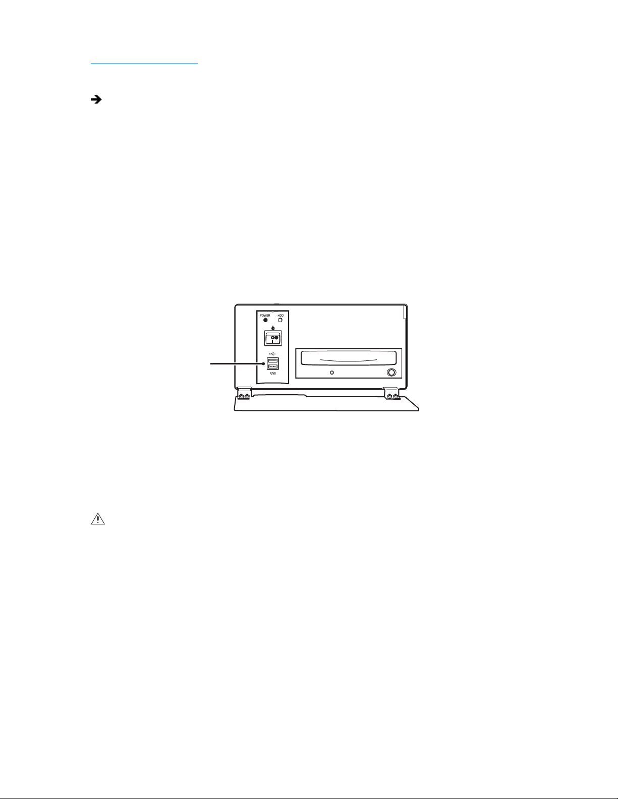
Clearing All Bookmarks
To clear all bookmarks:
Click Remove All Bookmarks.
INSERTING AND REMOVING A USB FLASH DRIVE
The DX8000 supports both USB 1.1 and USB 2.0 flash drives. To ensure data is not lost or corrupted when exporting data to a USB flash drive,
follow the steps listed in Removing a USB Flash Drive on page 93.
This section describes how to insert and remove a USB device and includes the following topics:
• Installing a USB Flash Drive on page 93
• Removing a USB Flash Drive on page 93
INSTALLING A USB FLASH DRIVE
This section describes how to install a USB flash drive. To install a USB flash drive into the DX8000:
1. Insert the USB drive into the USB 2.0 port on the DVR’s front panel.
Figure 61. Installing a USB flash drive
2. Wait five seconds while the DX8000 recognizes and automatically installs the device.
REMOVING A USB FLASH DRIVE
You can remove a USB device within the DX8000 environment. In this case, you do not have to exit to the Windows environment.
WARNING: Improperly removing a USB drive can cause data to be lost or corrupted.
To remove the USB flash drive from the DX8000:
1. Click > File Unplug/Eject Hardware. The Unplug or Eject Hardware dialog box opens.
2. Select the USB flash drive in the Hardware devices list.
3. Click Stop. The Stop a Hardware device dialog box opens.
4. Select the USB device.
5. Click OK.
6. Wait for the DX8000 to respond with a message stating that it is safe to remove the USB device from the DX8000. Removing a USB flash
drive before the DX8000 acknowledges that it is safe to remove the USB device might result in lost or corrupted data.
7. Remove the USB flash drive.
C624M-C (5/06) 93
Page 94
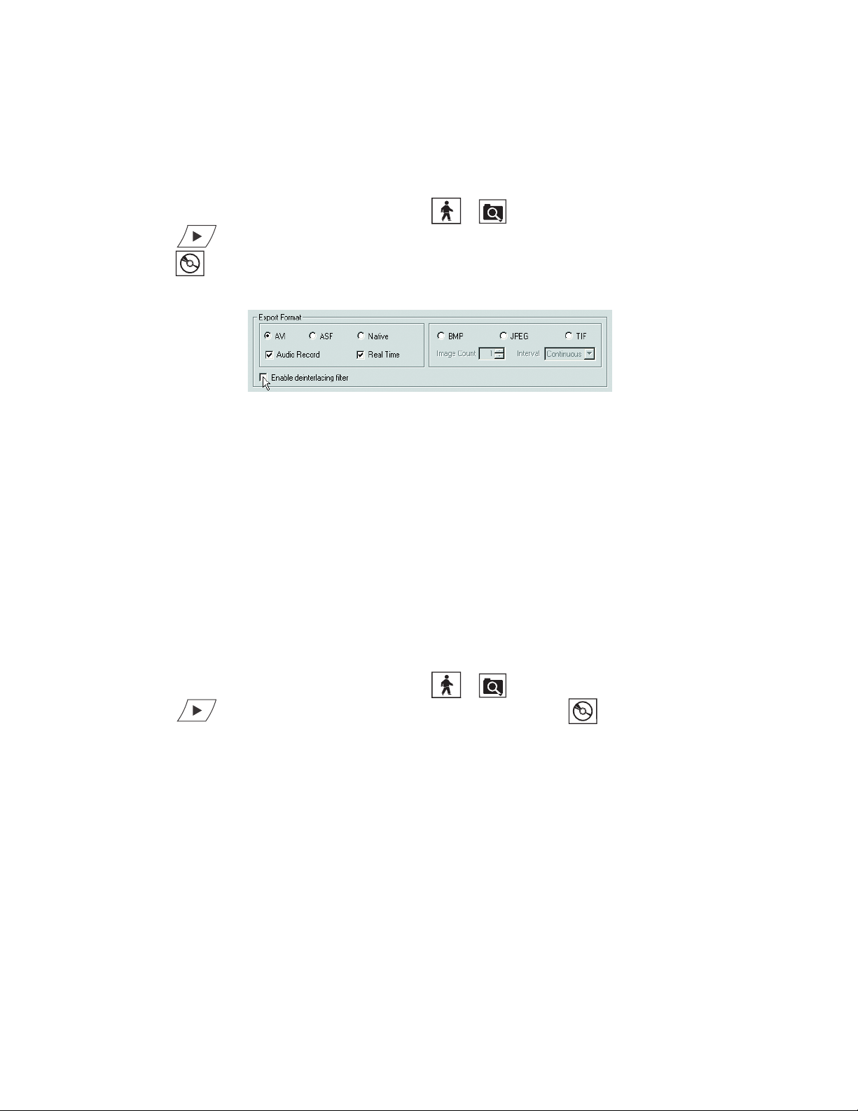
ENABLING THE DEINTERLACING FILTER
Images recorded at 4CIF at a low frame rate per second might move or tear. The DX8000 provides a global option for enabling deinterlacing
filtering to enhance the exported image for 4CIF recorded channels. In this case, the exported image is converted to 2CIF resolution. This setting
is effective for all channels, and cannot be set for enabling individual channels. For more information about the viewing video in the deinterlaced
mode, refer to Viewing Video in the Deinterlaced Mode on page 90.
To enable the deinterlacing filter:
1. Make sure the DVR is in Playback or Search mode by clicking or .
2. Click if you are in Live mode, or proceed to step 3 if you are in Search mode.
3. Click . The Export Video dialog box opens.
.
4. From the Export Format area, select the “Enable deinterlacing filter” check box.
Figure 62. Enabling the Deinterfacing Filter from the Export Video Dialog Box
MAPPING AND DISCONNECTING A NETWORK DRIVE
You can export sections of prerecorded video to a network drive. The DX8000 allows you to map to or disconnect from a network drive. In this
case, you must use the IP address of the target drive. The DX8000 allows you to use the host name of the target device. To do so, you must
enable NetBIOS option in the Windows environment. You need to know what letters are already assigned to drives and the path to the folder you
want to map.
This section describes how to map to and disconnect a network drive and includes the following topics:
• Mapping a Network Drive on page 94
• Disconnecting a Network Drive on page 95
MAPPING A NETWORK DRIVE
To map a network drive:
1. Make sure the DVR is in Playback or Search mode by clicking or .
2. Click if you are in Live mode, or proceed to step 3 if you are in Search mode. Click . The Export Video dialog box opens.
3. Click Map NetDrv. The Map Network Drive dialog box opens asking for a drive letter and path.
4. In the Drive drop-down box, select a drive letter that is not being used.
5. Type the path in the Folder drop-down box; \\IP_address_of_server\folder_name is an example.
6. (Optional) Click the “Reconnect at logon” box if you do not want the mapped drive to remain connected each time you logon.
7. Click Finish. The newly mapped drive is added as a remote drive and is displayed in the Device area. The mapped drive can now be
accessed just like a local drive.
94 C624M-C (5/06)
Page 95
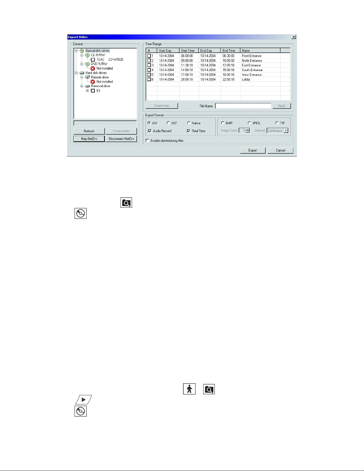
DISCONNECTING A NETWORK DRIVE
To disconnect a network drive:
1. On the DX8000 toolbar, click . The DX8000 is in the Search mode.
2. Click . The Export Video dialog box opens.
3. Click Disconnect NetDrv. The Disconnect Network Drive dialog box opens.
4. Select the network drive that you want to disconnect.
5. Click OK. The drive is disconnected and removed from the Export Video dialog box Device area.
PERFORMING THE EXPORT
This section describes how to export data and includes the following topics:
• Starting an Export Process on page 95
• Changing a Bookmarked Time Range on page 97
• Assigning a Custom Export Video File Name on page 97
• Selecting the Export Format on page 98
• Exporting a Sequence of Still Images on page 99
• Finalizing an Export Process on page 99
• Stopping an Export While in Process on page 100
• Working with DX8000 Backed-Up Video on page 100
Figure 63. Export Video Dialog Box
STARTING AN EXPORT PROCESS
To start the export process:
1. Make sure the DVR is in Playback or Search mode by clicking or .
2. Click if you are in Live mode, or proceed to step 3 if you are in Search mode.
3. Click . The Export Video dialog box opens.
4. Click the plus (+) sign next to a drive in the Device list. Available devices are indicated by a check box to the left of the device name.
C624M-C (5/06) 95
Page 96

5. Select the check box of the desired device. If you choose a remote device, select the drive and folder path where you would like to store the
exported file. You can also click the Browse button to access the file system for the appropriate folder.
If your DX8000 is connected to a network that supports shared folders and drives, you can map a network drive from within the Export Video
dialog box. For more information, refer to Mapping and Disconnecting a Network Drive on page 94.
The following table shows a listing of available devices.
Table AA. Available Backup Space
Type Description
Optical drives The DX8000 supports the following drives:
•CD-R
•DVD-R
Hard disk drives The hard disk drive can be any of the following:
• Local drives
• Remote drives
Removable drives USB flash drives
6. Select the check box of the video time range you want to export. You can export multiple time ranges simultaneously. For more information,
refer to Changing a Bookmarked Time Range on page 97.
7. Click in the File Name box, and then type the file name for each selected video time range. You can accept the default file name assigned to
the time range. For more information, refer to Assigning a Custom Export Video File Name on page 97.
8. Select the export format. For more information, refer to Selecting the Export Format on page 98.
9. Click Export.
10.0.1.14
Figure 64. Exporting Selected Video
96 C624M-C (5/06)
Page 97

CHANGING A BOOKMARKED TIME RANGE
To change a bookmarked time range or create a new time range to be exported:
1. Select the desired row in the Time Range table.
2. Double-click the Start Day field, and then use the spinner buttons to set the start date for the export.
The start days and times cannot be set later than end days and times.
3. Double-click the Start Time field, and then use the spinner buttons to set the start time for the export.
4. Double-click the End Day field, and then use the spinner buttons to set the end date for the export.
5. Double-click the End Time field, and then use the spinner buttons to set the end time for the export.
6. Select the check box next to each time range you would like to export.
Figure 65. Export Time Range
ASSIGNING A CUSTOM EXPORT VIDEO FILE NAME
By default, the DX8000 assigns a file name to each time range. When the video channel selected is exported, the file is assigned the name
appearing in the Name column.
Figure 66. Default File Names
The default filename is constructed from the information displayed in the Start Day, Start Time, End Day, and End Time columns.
To assign a custom file name for a time range:
1. Verify that the check box of the row you want to rename is selected.
2. Enter a file name for the file you want to export. (Export file names follow standard Windows file-naming conventions.)
3. Click Apply. The Apply button updates the Name field.
C624M-C (5/06) 97
Page 98

10.0.1.14
Figure 67. Renaming Export Time Ranges
SELECTING THE EXPORT FORMAT
The DX8000 allows you to select the export format. The following table shows the available export formats.
• Native format: When exporting video in the native format, the DX8000 embeds a digital watermark in the video stream for the purpose of
authentication. Watermarking ensures that an image has not been edited or damaged after it has been recorded. The watermark is an
encrypted, digital signature embedded in the video stream during the compression stage, protecting the video from the moment of creation.
The DX8000 Viewer software is capable of reading a DX8000 watermark and verifying the originality of the video.
• AVI or ASF format: Video exported in AVI or ASF format can be viewed using standard viewer software such as Windows Media Player.
When exporting video in the native format to a CD or DVD device, the DX8000 will automatically include the DX8000 Viewer application
along with the video. This viewer is designed to play a variety of still image, video, and audio media formats, including the native DX8000
format. The DX8000 Viewer application will automatically run each time a CD or DVD created by the DX8000’s export feature is inserted
into a Windows-based PC. To ensure that the viewer software runs automatically after the disk has been inserted, verify that the auto-run
feature of your PC’s optical drive has not been disabled.
Table AB. Export Formats
Format Description
AVI Saves video sequence as a standard Windows video format.
ASF Saves video sequence as a standard Windows media file.
Native Saves video sequence using DX8000’s proprietary compression format. Native format provides increased compression
and smaller file sizes.
BMP Saves a still image file in standard Windows bitmap format. Only the first frame of the video sequence is saved.
JPEG Saves a still image file in JPEG format. Only the first frame of the video sequence is saved.
TIFF Saves a still image file in TIF format. Only the first frame of the video sequence is saved
To select the export format:
From the Export Video dialog box, select the radio button of the file format you want to export.
98 C624M-C (5/06)
Page 99

EXPORTING A SEQUENCE OF STILL IMAGES
Still image formats export the first frame of a bookmarked region and then a single frame for each time interval until the number of images
specified has been exported. For example, consider exporting a six-hour bookmarked region of video with an image count of 100 and a time
interval of 3 seconds. The resulting export will include the first frame of the bookmarked region followed by 99 additional images taken at
3-second intervals. The first exported image will be the first frame of the bookmarked region and the last image will be the frame taken at
300 seconds into the bookmarked region.
To export a sequence of still images:
1. Select a still image format. Options are BMP, JPEG, and TIF.
2. Select the number of images (1 to 999) you want to save in the sequence.
3. Select the time interval between each saved image in the sequence. Options are as follows:
• Continuous
•0.5 seconds
•1 second
•2 second
•3 second
•4 seconds
•5 seconds
Figure 68. Still Image Export Formats
FINALIZING AN EXPORT PROCESS
This section describes how to finalize an export process. The following guidelines are applicable:
• Audio export is available only with DX8000 native, AVI, and ASF video formats.
• Real Time setting applies only to DX8000 native, AVI, and ASF video formats.
• When the Real Time check box is selected, the DX8000 will export video so it can be played back in real time (30 fps) for the same length of
time as the original recording. For example, if video was recorded at 1 fps, this means the DX8000 will insert 29 null frames for every
1 frame of actual video. Thus, one minute of video recorded at 1 fps (60 frames total) will play back for one minute at 30 frames per second
(60 frames of actual video interspersed with 1,740 null frames). If the Real Time check box is not selected, one minute of video recorded at
1 fps will play back in two seconds in real time. Figure 69 illustrates the two video streams: 1) one padded with null frames to match the
actual time duration and 2) another stream without null frames.
C624M-C (5/06) 99
Page 100

Figure 69. Real Time Versus Non-Real Time Export
To finalize the export process:
1. Make sure that the export media selected is inserted in the drive unit and that the drive is ready.
2. In the Time Range table, click selection box for each backed-up video time range you want to export.
3. In the Export Format section, do the following:
a. Click the Audio Record check box to include recorded audio.
b. Click the Real Time check box to export video using standard clock time.
4. Click Export to export video data.
STOPPING AN EXPORT WHILE IN PROCESS
Once an export operation has begun, a user can easily stop it by interrupting or canceling the operation from the Export menu on the main or
search screens. Interrupting an export simply stops the progress of the export while keeping all video information stored up to that point intact.
Canceling an export will delete any video data exported during the operation as well as ending the export itself.
This section describes how to stop an export process and includes the following topics:
• Retaining Video When Stopping an Export Process on page 100
• Deleting Video Data When Stopping an Export Process on page 100
Retaining Video When Stopping an Export Process
To halt an export that is in process while retaining video data stored to that point:
From the DX8000 menu bar, choose Export > Interrupt Export.
Deleting Video Data When Stopping an Export Process
To halt an export that is in process and delete any video data stored to that point:
From the DX8000 menu bar, choose Export > Cancel Export.
WORKING WITH DX8000 BACKED-UP VIDEO
The DX8000 allows you to view and search backed-up video. Use the DX8000 server to back up video. You must use the DX8000 Client
application to view backed-up video.
For more information about viewing backed-up video, refer to the section titled Viewing and Searching Backed-Up Video in the Client
Applications Help or the Client Applications manual and Viewing Backed-Up Video on page 170.
100 C624M-C (5/06)
 Loading...