

Page 1
INSTALLATION
®
Endura
™
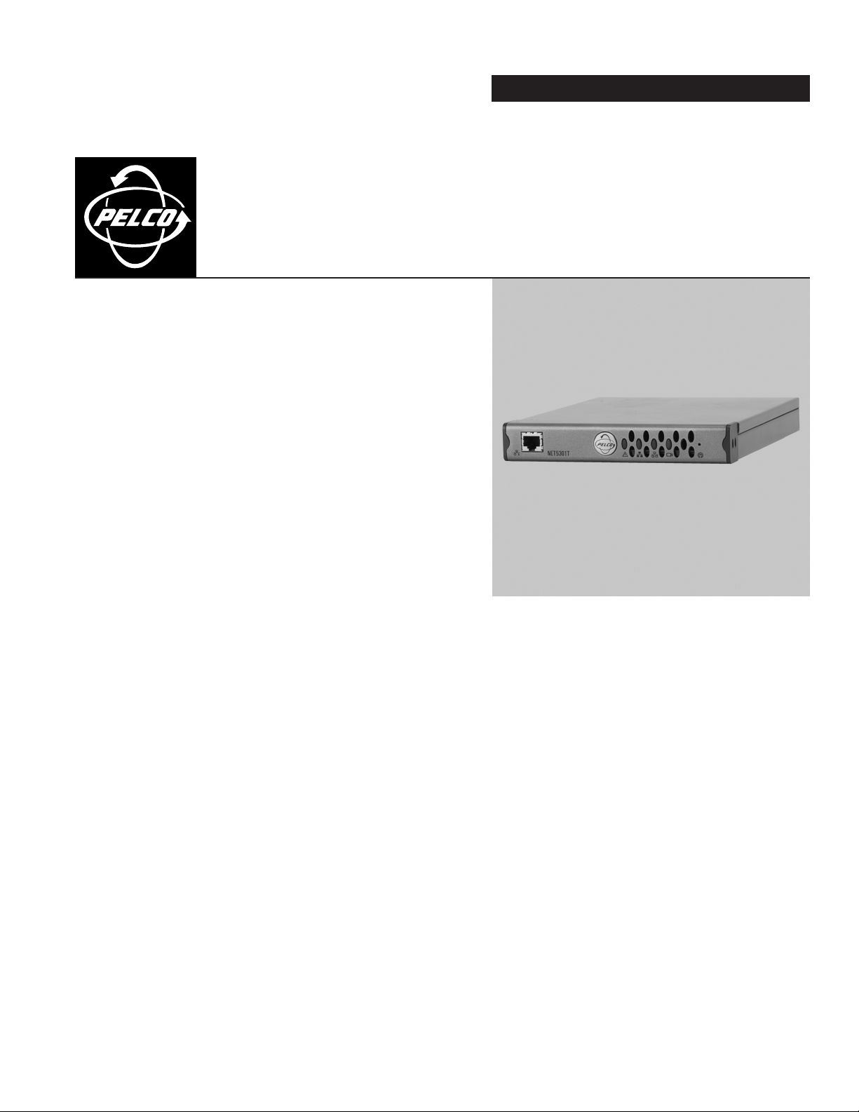
SP04-140 Dual-Input
Video Encoder
C613M-A (5/05)
Page 2

Contents
Regulatory Notices . . . . . . . . . . . . . . . . . . . . . . . . . . . . . . . . . . . . . . . . . . . . . . . . . . . . . . . . . . . . . . . . . . . . . . . . . . . . . . . . . . . . . . . . . . . . . . . . . . . .4
Description . . . . . . . . . . . . . . . . . . . . . . . . . . . . . . . . . . . . . . . . . . . . . . . . . . . . . . . . . . . . . . . . . . . . . . . . . . . . . . . . . . . . . . . . . . . . . . . . . . . . . . . . . .5
Before You Begin . . . . . . . . . . . . . . . . . . . . . . . . . . . . . . . . . . . . . . . . . . . . . . . . . . . . . . . . . . . . . . . . . . . . . . . . . . . . . . . . . . . . . . . . . . . . . . . . . . . . .5
Parts List . . . . . . . . . . . . . . . . . . . . . . . . . . . . . . . . . . . . . . . . . . . . . . . . . . . . . . . . . . . . . . . . . . . . . . . . . . . . . . . . . . . . . . . . . . . . . . . . . . . . . . .5
Product Serial Number Label Placement . . . . . . . . . . . . . . . . . . . . . . . . . . . . . . . . . . . . . . . . . . . . . . . . . . . . . . . . . . . . . . . . . . . . . . . . . . . . . . .6
Equipment Placement and Rack Mounting . . . . . . . . . . . . . . . . . . . . . . . . . . . . . . . . . . . . . . . . . . . . . . . . . . . . . . . . . . . . . . . . . . . . . . . . . . . . . . . . . . 7
Desktop Mounting . . . . . . . . . . . . . . . . . . . . . . . . . . . . . . . . . . . . . . . . . . . . . . . . . . . . . . . . . . . . . . . . . . . . . . . . . . . . . . . . . . . . . . . . . . . . . . . .7
Wall Mounting . . . . . . . . . . . . . . . . . . . . . . . . . . . . . . . . . . . . . . . . . . . . . . . . . . . . . . . . . . . . . . . . . . . . . . . . . . . . . . . . . . . . . . . . . . . . . . . . . . .8
Rack Mounting . . . . . . . . . . . . . . . . . . . . . . . . . . . . . . . . . . . . . . . . . . . . . . . . . . . . . . . . . . . . . . . . . . . . . . . . . . . . . . . . . . . . . . . . . . . . . . . . . . .9
Pelco Badge Orientation . . . . . . . . . . . . . . . . . . . . . . . . . . . . . . . . . . . . . . . . . . . . . . . . . . . . . . . . . . . . . . . . . . . . . . . . . . . . . . . . . . . . . . . . . . 10
Connections . . . . . . . . . . . . . . . . . . . . . . . . . . . . . . . . . . . . . . . . . . . . . . . . . . . . . . . . . . . . . . . . . . . . . . . . . . . . . . . . . . . . . . . . . . . . . . . . . . . . . . . .11
Connecting Video Inputs . . . . . . . . . . . . . . . . . . . . . . . . . . . . . . . . . . . . . . . . . . . . . . . . . . . . . . . . . . . . . . . . . . . . . . . . . . . . . . . . . . . . . . . . . .11
Connecting Audio . . . . . . . . . . . . . . . . . . . . . . . . . . . . . . . . . . . . . . . . . . . . . . . . . . . . . . . . . . . . . . . . . . . . . . . . . . . . . . . . . . . . . . . . . . . . . . . . 13
Connecting a PTZ Device, Relay, and Alarms . . . . . . . . . . . . . . . . . . . . . . . . . . . . . . . . . . . . . . . . . . . . . . . . . . . . . . . . . . . . . . . . . . . . . . . . . .14
Connecting Power . . . . . . . . . . . . . . . . . . . . . . . . . . . . . . . . . . . . . . . . . . . . . . . . . . . . . . . . . . . . . . . . . . . . . . . . . . . . . . . . . . . . . . . . . . . . . . .19
Connecting to the Network . . . . . . . . . . . . . . . . . . . . . . . . . . . . . . . . . . . . . . . . . . . . . . . . . . . . . . . . . . . . . . . . . . . . . . . . . . . . . . . . . . . . . . . .20
Connecting a PTZ Device (Pelco D Protocol) . . . . . . . . . . . . . . . . . . . . . . . . . . . . . . . . . . . . . . . . . . . . . . . . . . . . . . . . . . . . . . . . . . . . . . .15
Connecting a Relay Device . . . . . . . . . . . . . . . . . . . . . . . . . . . . . . . . . . . . . . . . . . . . . . . . . . . . . . . . . . . . . . . . . . . . . . . . . . . . . . . . . . . . 16
Connecting Alarms . . . . . . . . . . . . . . . . . . . . . . . . . . . . . . . . . . . . . . . . . . . . . . . . . . . . . . . . . . . . . . . . . . . . . . . . . . . . . . . . . . . . . . . . . .17
Operation . . . . . . . . . . . . . . . . . . . . . . . . . . . . . . . . . . . . . . . . . . . . . . . . . . . . . . . . . . . . . . . . . . . . . . . . . . . . . . . . . . . . . . . . . . . . . . . . . . . . . . . . . .21
Front Panel Indicators . . . . . . . . . . . . . . . . . . . . . . . . . . . . . . . . . . . . . . . . . . . . . . . . . . . . . . . . . . . . . . . . . . . . . . . . . . . . . . . . . . . . . . . . . . . . 21
Configuration/Reset Button . . . . . . . . . . . . . . . . . . . . . . . . . . . . . . . . . . . . . . . . . . . . . . . . . . . . . . . . . . . . . . . . . . . . . . . . . . . . . . . . . . . . . . . .22
Troubleshooting . . . . . . . . . . . . . . . . . . . . . . . . . . . . . . . . . . . . . . . . . . . . . . . . . . . . . . . . . . . . . . . . . . . . . . . . . . . . . . . . . . . . . . . . . . . . . . . . . . . . .23
Specifications . . . . . . . . . . . . . . . . . . . . . . . . . . . . . . . . . . . . . . . . . . . . . . . . . . . . . . . . . . . . . . . . . . . . . . . . . . . . . . . . . . . . . . . . . . . . . . . . . . . . . . .24
2 C613M-A (5/05)
Page 3

List of Illustrations
1 Product Serial Number Label . . . . . . . . . . . . . . . . . . . . . . . . . . . . . . . . . . . . . . . . . . . . . . . . . . . . . . . . . . . . . . . . . . . . . . . . . . . . . . . . . . . . . . . .6
2 SP04-140 Desktop Placement. . . . . . . . . . . . . . . . . . . . . . . . . . . . . . . . . . . . . . . . . . . . . . . . . . . . . . . . . . . . . . . . . . . . . . . . . . . . . . . . . . . . . . . .7
3 SP04-140 and WM5001-4U Wall Mount . . . . . . . . . . . . . . . . . . . . . . . . . . . . . . . . . . . . . . . . . . . . . . . . . . . . . . . . . . . . . . . . . . . . . . . . . . . . . . .8
4 Tighten the Thumbscrew to Secure the Unit . . . . . . . . . . . . . . . . . . . . . . . . . . . . . . . . . . . . . . . . . . . . . . . . . . . . . . . . . . . . . . . . . . . . . . . . . . . .8
5 Multiple SP04-140 Units in an RK5000PS-5U . . . . . . . . . . . . . . . . . . . . . . . . . . . . . . . . . . . . . . . . . . . . . . . . . . . . . . . . . . . . . . . . . . . . . . . . . . . 9
6 Tighten Thumbscrew to Secure the Unit . . . . . . . . . . . . . . . . . . . . . . . . . . . . . . . . . . . . . . . . . . . . . . . . . . . . . . . . . . . . . . . . . . . . . . . . . . . . . . .9
7 Pelco Badge Orientation . . . . . . . . . . . . . . . . . . . . . . . . . . . . . . . . . . . . . . . . . . . . . . . . . . . . . . . . . . . . . . . . . . . . . . . . . . . . . . . . . . . . . . . . . . . 10
8 SP04-140 Rear Panel . . . . . . . . . . . . . . . . . . . . . . . . . . . . . . . . . . . . . . . . . . . . . . . . . . . . . . . . . . . . . . . . . . . . . . . . . . . . . . . . . . . . . . . . . . . . .11
9 Video Inputs . . . . . . . . . . . . . . . . . . . . . . . . . . . . . . . . . . . . . . . . . . . . . . . . . . . . . . . . . . . . . . . . . . . . . . . . . . . . . . . . . . . . . . . . . . . . . . . . . . . .11
10 SP04-140 Audio Connections . . . . . . . . . . . . . . . . . . . . . . . . . . . . . . . . . . . . . . . . . . . . . . . . . . . . . . . . . . . . . . . . . . . . . . . . . . . . . . . . . . . . . . .13
11 SP04-140 Terminal Block . . . . . . . . . . . . . . . . . . . . . . . . . . . . . . . . . . . . . . . . . . . . . . . . . . . . . . . . . . . . . . . . . . . . . . . . . . . . . . . . . . . . . . . . . .14
12 Connecting a Spectra Dome . . . . . . . . . . . . . . . . . . . . . . . . . . . . . . . . . . . . . . . . . . . . . . . . . . . . . . . . . . . . . . . . . . . . . . . . . . . . . . . . . . . . . . . . 15
13 Connecting a Relay Device . . . . . . . . . . . . . . . . . . . . . . . . . . . . . . . . . . . . . . . . . . . . . . . . . . . . . . . . . . . . . . . . . . . . . . . . . . . . . . . . . . . . . . . . . 16
14 Supervised Alarm Conditions . . . . . . . . . . . . . . . . . . . . . . . . . . . . . . . . . . . . . . . . . . . . . . . . . . . . . . . . . . . . . . . . . . . . . . . . . . . . . . . . . . . . . . .17
15 Supervised Alarm Input Wiring . . . . . . . . . . . . . . . . . . . . . . . . . . . . . . . . . . . . . . . . . . . . . . . . . . . . . . . . . . . . . . . . . . . . . . . . . . . . . . . . . . . . .18
16 Unsupervised Alarm Conditions . . . . . . . . . . . . . . . . . . . . . . . . . . . . . . . . . . . . . . . . . . . . . . . . . . . . . . . . . . . . . . . . . . . . . . . . . . . . . . . . . . . . .18
17 Unsupervised Alarm Input Wiring . . . . . . . . . . . . . . . . . . . . . . . . . . . . . . . . . . . . . . . . . . . . . . . . . . . . . . . . . . . . . . . . . . . . . . . . . . . . . . . . . . .18
18 Connecting Alarms . . . . . . . . . . . . . . . . . . . . . . . . . . . . . . . . . . . . . . . . . . . . . . . . . . . . . . . . . . . . . . . . . . . . . . . . . . . . . . . . . . . . . . . . . . . . . . . 19
19 Connecting Power. . . . . . . . . . . . . . . . . . . . . . . . . . . . . . . . . . . . . . . . . . . . . . . . . . . . . . . . . . . . . . . . . . . . . . . . . . . . . . . . . . . . . . . . . . . . . . . .20
20 SP04-140 Front Panel . . . . . . . . . . . . . . . . . . . . . . . . . . . . . . . . . . . . . . . . . . . . . . . . . . . . . . . . . . . . . . . . . . . . . . . . . . . . . . . . . . . . . . . . . . . . . 21
List of Tables
A Video Coaxial Cable Requirements . . . . . . . . . . . . . . . . . . . . . . . . . . . . . . . . . . . . . . . . . . . . . . . . . . . . . . . . . . . . . . . . . . . . . . . . . . . . . . . . . .12
B PTZ, Relay, and Alarm Pin Assignments. . . . . . . . . . . . . . . . . . . . . . . . . . . . . . . . . . . . . . . . . . . . . . . . . . . . . . . . . . . . . . . . . . . . . . . . . . . . . . . 14
C Serial Port Options and Defaults . . . . . . . . . . . . . . . . . . . . . . . . . . . . . . . . . . . . . . . . . . . . . . . . . . . . . . . . . . . . . . . . . . . . . . . . . . . . . . . . . . . .16
D Powering Multiple Units. . . . . . . . . . . . . . . . . . . . . . . . . . . . . . . . . . . . . . . . . . . . . . . . . . . . . . . . . . . . . . . . . . . . . . . . . . . . . . . . . . . . . . . . . . .19
E Recommended Wire Gauge and Maximum Wiring Distances. . . . . . . . . . . . . . . . . . . . . . . . . . . . . . . . . . . . . . . . . . . . . . . . . . . . . . . . . . . . . .20
F Configuration/Reset Button Functions and Indicators . . . . . . . . . . . . . . . . . . . . . . . . . . . . . . . . . . . . . . . . . . . . . . . . . . . . . . . . . . . . . . . . . . . .22
G Troubleshooting the SP04-140 . . . . . . . . . . . . . . . . . . . . . . . . . . . . . . . . . . . . . . . . . . . . . . . . . . . . . . . . . . . . . . . . . . . . . . . . . . . . . . . . . . . . . .23
C613M-A (5/05) 3
Page 4

Regulatory Notices
This device complies with Part 15 of the FCC Rules. Operation is subject to the following two conditions: (1) this device may not cause harmful
interference, and (2) this device must accept any interference received, including interference that may cause undesired operation.
RADIO AND TELEVISION INTERFERENCE
This equipment has been tested and found to comply with the limits of a Class B digital device, pursuant to Part 15 of the FCC Rules. These limits
are designed to provide reasonable protection against harmful interference in a residential installation. This equipment generates, uses, and can
radiate radio frequency energy and, if not installed and used in accordance with the instructions, may cause harmful interference to radio
communications. However there is no guarantee that the interference will not occur in a particular installation. If this equipment does cause
harmful interference to radio or television reception, which can be determined by turning the equipment off and on, the user is encouraged to try
to correct the interference by one or more of the following measures:
• Reorient or relocate the receiving antenna.
• Increase the separation between the equipment and the receiver.
• Connect the equipment into an outlet on a circuit different from that to which the receiver is connected.
• Consult the dealer or an experienced radio/TV technician for help.
You may also find helpful the following booklet, prepared by the FCC: “How to Identify and Resolve Radio-TV Interference Problems.” This
booklet is available from the U.S. Government Printing Office, Washington D.C. 20402.
Changes and Modifications not expressly approved by the manufacturer or registrant of this equipment can void your authority to operate this
equipment under Federal Communications Commission’s rules.
In order to maintain compliance with FCC regulations, shielded cables must be used with this equipment. Operation with non-approved
equipment or unshielded cables is likely to result in interference to radio and television reception.
This Class B digital apparatus complies with Canadian ICES-003.
Cet appareil numérique de la classe B est conforme à la norme NMB-003 du Canada.
4 C613M-A (5/05)
Page 5

Description
The SP04-140 is a special version of the single-input NET5301T video encoder. It is a high-performance, dual-stream, dual-input video encoding
unit. Its main function is to convert live analog video from two cameras into dual MPEG-4 video streams. It transmits these streams over an
Ethernet network to other Endura
recorder or decoded by the following Endura components:
• NET5301R video decoder: Converts up to 4 video streams for display or recording on an analog device.
• WS5050 workstation: Converts up to 16 video streams for display on a computer monitor.
• VCD5000 video console display: Converts up to 64 video streams (depending on model) for display or recording on an analog device.
NOTE: The front panel of the SP04-140 shows NET5301T as the model. However, the special number appears on the product serial number label
on the unit’s bottom panel.
The SP04-140 incorporates EnduraView
product (decoder, workstation, console), all without affecting the system recording rate. For example, the unit selects a high rate and quality
setting for recording and alarm conditions; it selects a lower rate for simple monitoring.
The SP04-140 can be configured for three alarm inputs and one relay output. When an alarm event is triggered, the unit can send a message to
an operator, trigger a relay, and implement video recording.
The unit also supports activity detection. You can configure up to four activity zones. When the SP04-140 detects activity in any of these areas, it
can trigger an alarm event.
The video encoder supports half-duplex, bidirectional audio over the network. The system operator (security personnel) can see and hear the
person.
All Endura products support Pelco D and Coaxitron
(PTZ) cameras.
™
system components. Then these streams can be recorded on an Endura NVR5100 Series network video
™
video optimization technology to select the best image quality and frame rate for the target Endura
®
protocols. As a result, the SP04-140 supports control of remote peripherals such as pan/tilt/zoom
Before You Begin
Endura is a network system that requires a continuous amount of bandwidth to transmit true, live video. Therefore, always include your network
administrator when planning and installing Endura components.
You will also need the following:
• Pelco-approved Endura certification
• Power source
• One or two NTSC or PAL (fixed or PTZ) cameras
• Microphone and speaker (if using audio)
• Small flat-tip screwdriver (if connecting camera control, relay, or alarms)
• Access to an Endura network
NOTE: Since power requirements vary by installation, the SP04-140 does not include an individual power supply. You can purchase the optional
NET5301PS single-unit power supply from Pelco. Refer to Connecting Power for more information on supplying power to the SP04-140.
PARTS LIST
Qty Description
1 SP04-140 dual-input video encoder
1 16-pin terminal block
1Two-pin power terminal block
1 SP04-140 Installation manual
1 Pelco badge rotation sticker
C613M-A (5/05) 5
Page 6
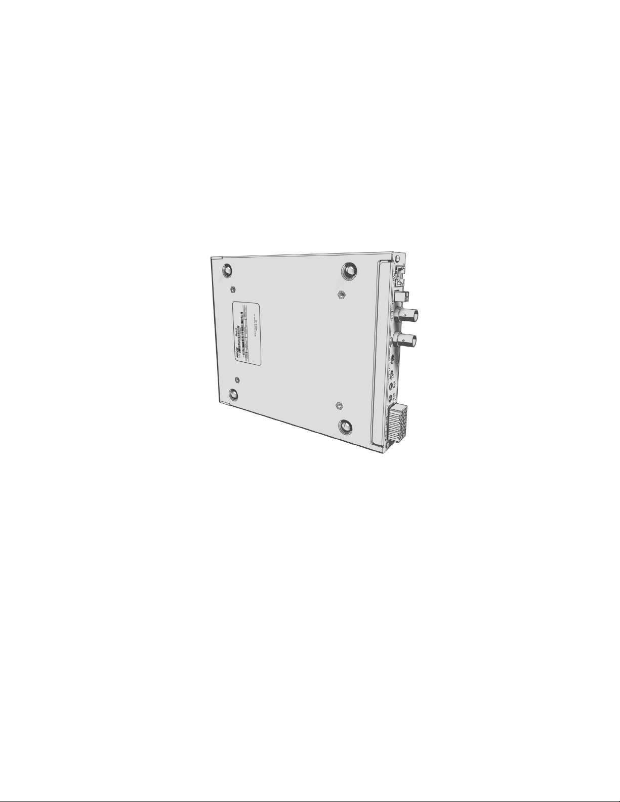
PRODUCT SERIAL NUMBER LABEL PLACEMENT
Product serial number labels help Pelco’s Product Support identify your system and its factory configuration in case the SP04-140 or its
components require service.
A label citing your product’s serial number is attached to the bottom panel of the SP04-140. Because rack mounting or other installation options
may obscure the factory-applied label, two additional labels are provided. Attach one of them to your product documentation or another product
location that will not be obscured by installation. The second label is a spare.
To use these labels:
1. On the bottom panel of your SP04-140, locate two small labels, attached with a yellow sticker that reads, “Extra serial number labels:
remove prior to installation.”
2. Remove the yellow sticker and the labels.
3. Peel away the backing from one label and attach it to this installation manual, other product documentation, or an unobscured product
location.
Figure 1. Product Serial Number Label
6 C613M-A (5/05)
Page 7
Equipment Placement and Rack Mounting
The SP04-140 can be placed on a flat surface, such as a desktop; mounted to a wall; or mounted into an equipment rack.
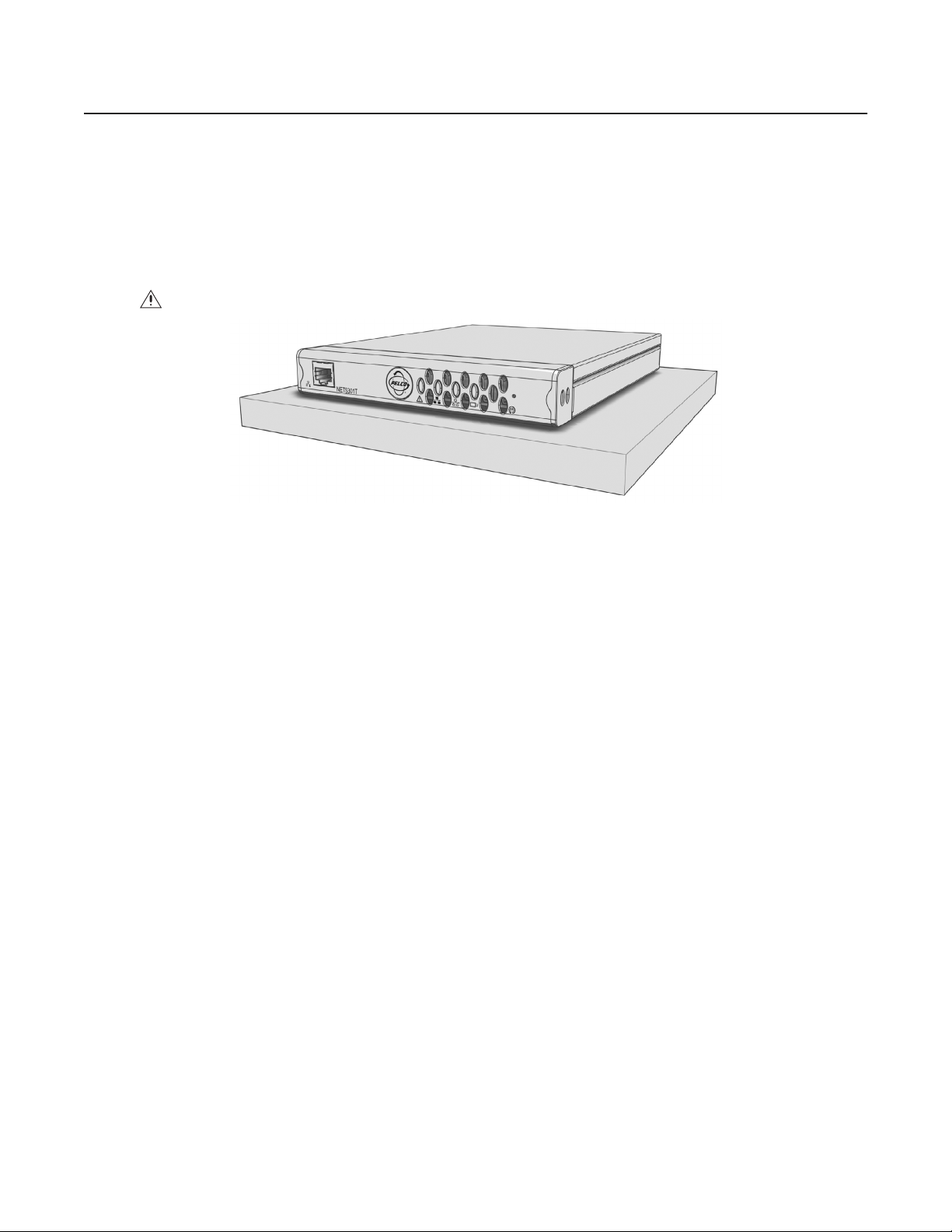
DESKTOP MOUNTING
To place the SP04-140 on a flat surface, such as a desktop:
1. Make sure the rubber feet are installed on the unit to prevent surface damage.
2. Position the unit to allow for cable and power cord clearance at the front and rear panels.
WARNING: Do not place the SP04-140 unit on its side; the unit could fall over and cause damage.
Figure 2. SP04-140 Desktop Placement
C613M-A (5/05) 7
Page 8
WALL MOUNTING
The SP04-140 can be mounted to a wall using the optional WM5001-4U wall mount system. You can mount up to four SP04-140, NET5301T, and
NET5301R units, in any combination, in a fully expanded WM5001-4U (one WM5001-4U with up to three WM5001-4UEXP expansion units).
To mount the SP04-140 to a wall using the WM5001-4U:
1. Install the WM5001-4U and any WM5001-4UEXP expansion units (refer to the WM5000 installation manual).
2. Insert the SP04-140 into the desired wall mount unit. Make sure all front and rear panel connectors are accessible.
Figure 3. SP04-140 and WM5001-4U Wall Mount
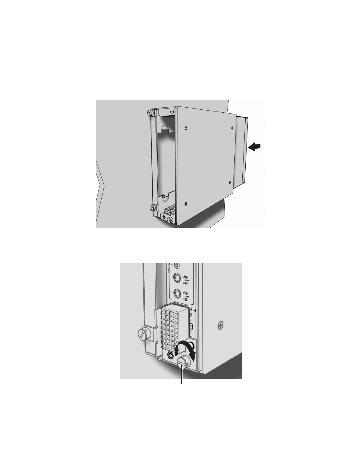
3. Tighten the thumbscrew on the wall mount to secure the unit (refer to Figure 4).
TIGHTEN
THUMBSCREW
Figure 4. Tighten the Thumbscrew to Secure the Unit
8 C613M-A (5/05)
Page 9
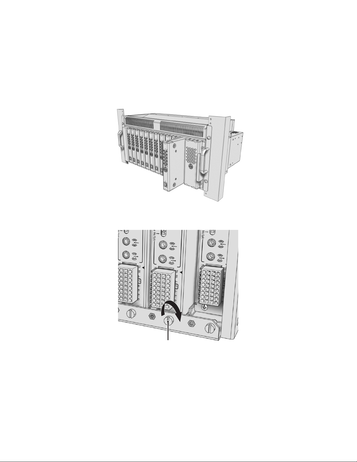
RACK MOUNTING
Any combination of SP04-140, NET5301T, and NET5301R units can be mounted together in the optional RK5000PS-5U rack mount kit, up to 12
units. Each unit plugs directly into a power connector in the rack and is powered by the rack.
NOTE: The RK5000PS-5U only supplies power. It does not provide a dock for any other unit connectors.
To install the SP04-140 into a rack mount kit:
1. Install the RK5000PS-5U rack mount kit into the rack (refer to the RK5000PS-5U installation manual).
2. Insert the SP04-140 into the desired slot.
Figure 5. Multiple SP04-140 Units in an RK5000PS-5U
3. Tighten the thumbscrew on the rack mount to secure the unit into the rack (refer to Figure 6).
TIGHTEN
THUMBSCREW
Figure 6. Tighten Thumbscrew to Secure the Unit
C613M-A (5/05) 9
Page 10

PELCO BADGE ORIENTATION
The Pelco badge on the front panel of the SP04-140 can be rotated in quarter turns. If you install the unit on a flat surface, the Pelco badge will
be turned the wrong way.
To rotate the Pelco badge:
1. Use the Pelco badge rotation sticker that came with the unit.
2. Attach the middle portion of the rotation sticker to the badge.
3. Press firmly with your thumb and rotate the badge to its correct position.
4. Remove the rotation sticker from the badge.
PELCO BADGE
Figure 7. Pelco Badge Orientation
10 C613M-A (5/05)
Page 11

Connections
Familiarize yourself with the SP04-140 rear panel before connecting any equipment to the unit.
FOUR-PIN
POWER
TWO-PIN
POWER
CONNECTING VIDEO INPUTS
The SP04-140 offers two analog video inputs. The unit automatically detects the video standard (PAL or NTSC) and accepts both color and
black-and-white analog video at both inputs.
The Video In (2) connector also supports PTZ operation using the following protocols:
• Coaxitron: When the SP04-140 receives a camera control command, it transmits that command up the coaxial cable to the PTZ device.
Since Coaxitron is a single-direction protocol, the PTZ device cannot return any data to the unit. By default, Coaxitron is disabled.
• Pelco D (RS-422): When the SP04-140 receives a camera control command, it transmits that command via the serial wires to the PTZ
device. Pelco D is a bidirectional protocol.
TERMINATION SWITCH AUDIO SWITCH RELAY CONTROL
VIDEO IN (1) VIDEO IN (2)
AUDIO IN AUDIO OUT
PTZ CONTROL (RS-422)
Figure 8. SP04-140 Rear Panel
ALARM
INPUT
CAMERA 1 (FIXED)
VIDEO IN (1)
CAMERA 2
(FIXED OR PTZ)
VIDEO IN (2)
Figure 9. Video Inputs
C613M-A (5/05) 11
Page 12

Before installing the SP04-140, make sure the distance from the unit to the video device is less than the maximum distance for the coaxial cable.
Refer to Table A for maximum video coaxial cable distances.
Table A. Video Coaxial Cable Requirements
Cable Type* Maximum Distance
RG59/U 750 ft (229 m)
RG6/U 1,000 ft (305 m)
RG11/U 1,500 ft (457 m)
*Cable requirements:
75-ohm impedance
All-copper center conductor; steel-center conductor cable may result in poor performance
All-copper braided shield with 95% braid coverage
NOTE: Make sure the termination switch is set to 75 Ω to enable termination. This is the default.
To connect a fixed camera:
1. Connect a coaxial cable to the camera device.
2. Connect the coaxial cable to the video in (1) connector on the rear panel.
To connect a second fixed camera:
1. Connect a coaxial cable to the camera device.
2. Connect the coaxial cable to the video in (2) connector on the rear panel.
To connect a PTZ device:
1. Connect a coaxial cable to the PTZ device.
2. Connect the coaxial cable to the video in (2) connector.
3. Pelco D only: Wire the TX and RX leads from the encoder to the PTZ device. Refer to Connecting a PTZ Device (Pelco D Protocol) .
12 C613M-A (5/05)
Page 13

CONNECTING AUDIO
The SP04-140 supports half-duplex, bidirectional audio (one direction at a time). It transmits audio and video signals simultaneously. This lets
you control a loudspeaker or other audio equipment, such as a door intercom system, at the monitored location.
The unit supports both microphone and line input levels. Microphones are usually not powered; they have weaker signals that must be amplified.
Line inputs usually have stronger, powered signals that have already been amplified.
NOTE: Use either microphone/speaker or line in/line out. The SP04-140 does not support mixed audio signal inputs and outputs.
MIC/SPKR
LINE
AUDIO PREAMP
Figure 10. SP04-140 Audio Connections
To implement audio:
1. Select the type of audio signal:
Mic/Spkr
Switch to Mic/Spkr if you are connecting a microphone or a speaker. The microphone input level is 5 mVp-p. The speaker
output level is 2.5 Vp-p.
Line
Switch to Line if you are connecting a powered audio input or output device. The line input and output level is 1 Vp-p.
By default, the switch is set to Line.
NOTE: If the switch setting does not match your audio equipment, audio distortion problems may occur.
2. Make sure the input and output audio connectors are wired as follows:
Connector Tip
Signal high
Connector Sleeve Common
3. Connect a line input device or microphone to the blue 3.5 mm audio in monaural connector. A preamplified microphone is recommended.
4. Connect a line output device or speaker to the green 3.5 mm audio out monaural connector.
NOTE: Audio out is not supported at this time.
C613M-A (5/05) 13
Page 14

CONNECTING A PTZ DEVICE, RELAY, AND ALARMS
The SP04-140 incorporates a 16-pin terminal block to support the following:
• PTZ device, such as a dome camera, using the Pelco D protocol (RS-422)
• Relay control, either normally open or normally closed
• Up to three alarm inputs, supervised or unsupervised, using any combination of high and low signals
The terminal block has tension clamps instead of screw terminals. Use a small screwdriver to open the clamp for a particular lead. Figure 11
shows how to wire the terminal block and connect it to the SP04-140.
NOTE: The terminal block is keyed. It attaches only one way to the video encoder.
PIN 1 PIN 1
PIN 9
PIN 16
Figure 11. SP04-140 Terminal Block
Table B identifies the pin assignments for the terminal block. An arrow on the rear panel identifies pin 1; on the terminal block, pin 1 is the
leftmost lead on the top row (refer to Figure 11).
Table B. PTZ, Relay, and Alarm Pin Assignments
Top Row Bottom Row
Pin Label Lead Pin Label Lead
1 TX- RS-422 Data TX- 9 TX+ RS-422 Data TX+
2 RX- RS-422 Data RX- 10 RX+ RS-422 Data RX+
3 Ground 11 NC Relay Normally Closed
4CRelay Common 12 NO Relay Normally Open
5 Ground 13 Ground
1
6A
7A
8A
Alarm 1 14 Ground
2
Alarm 2 15 Ground
3
Alarm 3 16 Ground
14 C613M-A (5/05)
Page 15

CONNECTING A PTZ DEVICE (PELCO D PROTOCOL)
NOTE: To connect a Coaxitron PTZ device, refer to Connecting Video Inputs
The SP04-140 supports camera control using Pelco D protocol (RS-422) for a PTZ device. You can connect only one serial PTZ device to a video
encoder. The default Pelco D device address is 0.
When the SP04-140 receives a camera control command, it transmits that command to the PTZ device. In four-wire installations, the encoder
also receives data from the PTZ device, including camera status and alarm states. It then transmits that data to the command center.
®
Figure 12 shows how to wire the SP04-140 to a Spectra
NOTE: When connecting a PTZ device to the SP04-140, connect the TX+ and TX- leads to the RX+ and RX- leads between the encoder and the
PTZ device.
By default, the encoder identifies any PTZ device as a fixed camera. You must configure the encoder before you can use the PTZ device (refer to
the WS5000 operation manual).
dome (refer to Table B for the specific connector pin assignments).
TX+
TX-
RXRX+
1VIDEO IN ( )
COAXIAL CABLE
VIDEO IN (2)
TRANSMIT
TO SPECTRA
RECEIVE
FROM SPECTRA
TX-TX+ RX+
RX-
SPECTRA
Figure 12. Connecting a Spectra Dome
C613M-A (5/05) 15
Page 16

Refer to Table C when installing the PTZ device. It lists the serial port settings that the SP04-140 supports.
Table C. Serial Port Options and Defaults
Setting Options Default
Data rate (bits per
second)
110, 300, 1200, 2400, 4800, 9600, 19200, 38400, 57600,
115200, 230400
2400
Data bits 5, 6, 7, 8 8
Parity None, Odd, Even None
Stop bits 1, 2 1
CONNECTING A RELAY DEVICE
The SP04-140 has an output for triggering an external device. It supports both momentary and continuous relay operation.
You can operate the relay interactively, during an active connection, or automatically to coincide with certain events. Typical applications include
activating a door, gate or lock, or switching on lights or other electrical devices.
WARNING: Do not exceed the maximum rating of 30 VDC, 1 A.
Figure 13 shows how to wire the relay with its power source to the video encoder (refer to Table B for the specific connector pin assignments).
NO
EXTERNAL
C
FUSE
MAX 30 VDC, 1 A
LIGHT/SIREN
POWER
Figure 13. Connecting a Relay Device
LOAD:
16 C613M-A (5/05)
Page 17

CONNECTING ALARMS
The SP04-140 offers three alarm inputs for external signaling devices, such as door contacts or motion detectors. Each encoder supports either
all normally open or all normally closed devices. If your installation requires mixed devices, install another SP04-140, NET5301T, or a NET5301R
video decoder. Then connect the normally open devices to one unit and the normally closed devices to the other unit.
Once configured, an alarm input can invoke many different activities, including triggering a relay device, sending an alert to a security office,
changing the video recording settings, and storing pre-alarm video to an NVR5100 Series recorder. You can connect switches or contacts directly
to the unit without a separate power supply.
Each encoder supports either all supervised or all unsupervised alarms. If your installation requires mixed alarm types, install another SP04-140,
NET5301T, or a NET5301R video decoder. Then connect the supervised alarm inputs to one unit and the unsupervised alarm inputs to the other
unit.
Supervised Alarms
When an alarm is configured as a supervised alarm, the SP04-140 maintains a constant electrical current through the alarm circuit (3.3 VDC,
1 k Ω ). If the alarm circuit length changes, due to an electrical short or a bypass, the voltage fluctuates from its normal state. Therefore, the unit
triggers an alarm.
NOTE: Install the 1 k Ω resister as close to the switch as possible.
Figure 14 illustrates the alarm and no alarm conditions of a supervised alarm input. Whether the alarm is normally closed or normally open,
neither a cut nor a bypass can defeat these alarms.
NORMALLY CLOSED
NO ALARM
GND
ALARM
GND
ALARM
GND
ALARM
GND
1 K
1 K
1 K
1 K
+V
+V
+V
CUT
+V
BYPASS
NO ALARM
ALARM
ALARM
ALARM
Figure 14. Supervised Alarm Conditions
NORMALLY OPEN
GND
GND
GND
CUT
GND
1 K
1 K
1 K
1 K
BYPASS
+V
+V
+V
+V
C613M-A (5/05) 17
Page 18

Figure 15 illustrates the wiring configuration for supervised alarm inputs.
NORMALLY CLOSED
1 KΩ
1 KΩ
1 KΩ
UNUSED
INPUTS
MUST ALSO
BE WIRED
NORMALLY OPEN
1 KΩ
1 KΩ
1 K
Ω
UNUSED
INPUTS
MUST ALSO
BE WIRED
Figure 15. Supervised Alarm Input Wiring
Unsupervised Alarms
When an alarm is configured as an unsupervised alarm, the SP04-140 only triggers an alarm when the normal alarm state (open or closed)
changes.
Figure 16 illustrates the alarm and no alarm conditions of an unsupervised alarm input. A normally closed alarm input can be defeated with a
bypass. A normally open input can be defeated with a cut.
NORMALLY CLOSED
NO ALARM
GND
ALARM
GND
ALARM
GND
NO ALARM
GND
CUT
+V
+V
+V
+V
NO ALARM
GND
ALARM
GND
NO ALARM
GND
ALARM
GND
NORMALLY OPEN
CUT
+V
+V
+V
+V
BYPASS
Figure 16. Unsupervised Alarm Conditions
Figure 17 illustrates the wiring configuration for unsupervised alarm inputs.
NORMALLY CLOSED
UNUSED
INPUTS
MAY BE
SHORTED
Figure 17. Unsupervised Alarm Input Wiring
BYPASS
NORMALLY OPEN
UNUSED
INPUTS
MUST BE LEFT
UNWIRED
18 C613M-A (5/05)
Page 19

Alarm Connections
Figure 18 shows how to wire the video encoder to an alarm (refer to Table B for the specific connector pin assignments).
Figure 18. Connecting Alarms
CONNECTING POWER
The SP04-140 video encoder is designed to operate from either a 12 VDC or a 24 VAC power supply. It automatically senses power type and
polarity (DC).
The SP04-140 can be powered from many sources:
• NET5301PS power supply connects directly to the four-pin connector on the SP04-140 rear panel.
• The RK5000PS-5U rack mount kit supplies power through the four-pin connector on the SP04-140 rear panel as soon as the unit slides into
place.
• The Pelco MCS (B model), WCS (B model), and TF Series power supplies provide power through a two-pin terminal block (supplied) that
plugs into the two-pin connector on the SP04-140 rear panel.
• Other UL Listed direct plug-in power units marked “Class 2” and rated for 12 VDC +10%/-15% or 24 VAC +10%/-15% provide power
through a two-pin terminal block (supplied) that plugs into the two-pin connector on the SP04-140 rear panel.
The power consumption of the SP04-140 is eight watts (13.3 VA).
Use Table D to estimate your power requirements when installing multiple SP04-140, NET5301T, and NET5301R units. This table is based on a
24 VAC power supply.
Model
NET5301T
SP04-140
NET5301R 1 2 2 4 5 11 24
Table D. Powering Multiple Units
Units Powered
at 20 VA at 48 VA at 50 VA at 100 VA at 120 VA at 240 VA at 480 VA
133 7 9 18 36
C613M-A (5/05) 19
Page 20

Use Table E to help identify the necessary wire gauge and maximum cable distance. This table applies to two-conductor solid copper wire.
(Reduce distance by 10% for stranded copper wire.) These maximum distances are based on a maximum allowable voltage drop of 10%.
Table E. Recommended Wire Gauge and Maximum Wiring Distances
Wire Gauge
20 AWG (0.5 mm
18 AWG (1.0 mm
16 AWG (1.5 mm
14 AWG (2.5 mm
12 AWG (4.0 mm
10 AWG (6.0 mm
2
) 89 ft (27 m) 356 ft (108 m)
2
) 141 ft (42 m) 566 ft (172 m)
2
) 224 ft (68 m) 899 ft (274 m)
2
) 357 ft (108 m) 1,428 ft (435 m)
2
) 566 ft (172 m) 2,267 ft (690 m)
2
) 900 ft (274 m) 3,600 ft (1,097 m)
Maximum Distance
12 VDC 24 VAC
Connect power to the SP04-140. The Pelco badge (blue) and the status light (green) on the front panel should glow.
CONNECTING TO THE NETWORK
When using one or more network switches with the Endura system, make sure you enable auto negotiation on all switches.
Connect the SP04-140 video encoder to your network:
1. Connect a 10/100/1000BaseT network Cat5e (or better) cable to the RJ-45 network connector on the front panel. The encoder
automatically searches the network for other Endura components.
2. Check the indicators on the front panel. They show network connection speed and status (refer to Front Panel Indicators ).
FOUR-PIN OR TWO-PIN
Figure 19. Connecting Power
20 C613M-A (5/05)
Page 21

Operation
Refer to the WS5000 operation manual for details on how to access and configure the SP04-140 video encoder.
FRONT PANEL INDICATORS
NETWORK CONNECTOR
Pelco badge (power)
The Pelco badge glows blue when the unit has power.
NETWORK STATUS
NETWORK ACTIVITY
UNIT STATUS
Figure 20. SP04-140 Front Panel
VIDEO
PRESENCE
CONFIGURATION/
RESET BUTTON
Unit status
Unit status is indicated by one of the following three colors:
Green
Amber
Red
Whenever the unit status indicator is flashing, the unit is in one of three system modes (refer to Configuration/Reset Button ).
The unit is functioning normally.
The unit is in configuration mode.
The unit is in an error condition.
Network status
Network status (connection and speed) is indicated by one of the following conditions:
Off
Solid Amber The unit is connected to the network using the 100BaseT standard.
Solid Red The unit is connected to the network using the 10BaseT standard.
NOTE: For optimum performance, Pelco recommends using the 100 BaseT standard.
The unit is not connected to the network.
Network activity
The network activity indicator flashes whenever the video encoder is sending or receiving network data.
Video presence
Video presence is indicated by one of the following conditions:
Green
Red Camera video is present at the video in (1) connector. The indicator is also red if there is no video to both video connectors.
Camera video is present at the video in (2) connector, or both video in connectors.
C613M-A (5/05) 21
Page 22

CONFIGURATION/RESET BUTTON
Use the recessed configuration/reset button at the top of the front panel to access the following modes:
Table F. Configuration/Reset Button Functions and Indicators
Mode Function Unit Status Indicator Light
Configuration Initiates system configuration.
Reboot Restarts the unit.
Reset
Cancel Cancels any configuration or reset action. • No light
To access one of these modes:
1. Use a probe or paper clip to press and hold the configuration/reset button . The unit starts cycling through the four modes
(configuration, reboot, reset, and cancel), holding each mode for five seconds. The unit status indicator flashes the color for the current
mode.
2. When the color of the desired mode appears, release the button.
NOTE: If there is no configuration activity for 15 minutes, the SP04-140 automatically exits configuration/reset mode.
Resets unit to factory default settings and then
restarts unit.
• Flashing amber when entering this mode
• Solid amber when selected
• Flashing green when entering this mode
• Flashing green when selected and during restart
• Flashing red when entering this mode
• Flashing red when selected, then flashing green during
restart
22 C613M-A (5/05)
Page 23

Troubleshooting
If the following instructions fail to solve your problem, contact Pelco Product Support at 1-800-289-9100 or 1-559-292-1981 for assistance.
Access the properties windows for the SP04-140 video encoder on the WS5050 workstation (refer to the WS5000 operation manual). Then note
the following before calling Pelco:
• Unit serial number: located on the Properties window and on the product label
• Unit firmware version: located on the Advanced Properties window, listed for the Encoder Device
Do not try to repair the unit yourself. Opening it immediately voids any warranty. Leave maintenance and repairs to qualified technical personnel.
Exchange the defective unit and return it for repair.
Problem Possible Causes Suggested Remedy
No video transmission Power turned off Check that the SP04-140 is switched on and
No audio transmission to receiver Faulty cable connection Check all leads, plugs, contacts, and
Cannot control PTZ cameras or other
devices
The unit is not ready for operation after
firmware upload
Table G. Troubleshooting the SP04-140
the power indicator is lit.
Faulty cable connections Check all leads, plugs, contacts, and
connections.
Defective camera Connect local monitor and check camera
function.
Defective encoder Check camera on a different encoder.
Network connectivity issues Contact your network administrator.
connections.
Defective hardware Check functioning of all connected audio
devices.
Connection in use by another receiver Wait until the connection is free and try again.
Faulty cable connection Check all cable connections and ensure all
plugs are properly plugged in.
Network connectivity issues Contact your network administrator.
Incorrect PTZ settings Change the camera settings on the WS5050
workstation.
PTZ camera connected to the video in (1)
connector
Voltage failure during programming of update
file
Connect the PTZ camera to the video in (2)
connector.
Replace the device and have it checked by
Pelco.
C613M-A (5/05) 23
Page 24

Specifications
MODEL NUMBER
SP04-140 Dual-input network video server that encodes video, audio, and control data for transmission over an
SUPPLIED ACCESSORIES
Mating Connectors One 16-pin, one 2-pin
SYSTEM
Processor PowerPC
Operating System Linux
User Interface Remote operation via WS5050 or VCD5000
VIDEO/AUDIO
Video Standards NTSC/PAL/EIA/CCIR composite
Video Coding MPEG-4
Video Streams 2, simultaneous
Video Resolutions NTSC
4CIF 704 x 480 704 x 576
2CIF 704 x 240 704 x 288
CIF 352 x 240 352 x 288
QCIF 176 x 120 176 x 144
Video Inputs/Connectors 2, BNC, 75 Ω, 1 Vp-p
Video Switch Hi-Z, 75Ω
Audio Encoding G.711 speech codec
Audio Bit Rate 64 kbps
Audio Levels
Line In/Line Out 1 Vp-p, 10 kΩ
Microphone 5 mVp-p, approximately 40 kΩ
Speaker 2.5 Vp-p, 30 mW, minimum 16 Ω
Audio Connectors Two 3.5 mm monaural
Connector Tip Signal high (input and output)
Connector Sleeve Common
Audio Inputs Microphone or line in
Audio Outputs Speaker or line out
Audio Switch Line, microphone/speaker
IP network
®
®
405EP
PAL
PTZ CONTROL
PTZ Interface RS-422, video in
PTZ Protocols Pelco D (RS-422), Coaxitron
ALARMS/RELAYS
Alarm Inputs 3, programmable, 3.3 VDC, 1 kΩ, triggered; uses 6 of 16 pins on terminal block connector
Relay Output 1, form-C relay, 30 VDC, 1 A; uses 3 of 16 pins on terminal block connector
24 C613M-A (5/05)
Page 25

VIDEO ACTIVITY DETECTION
Zones 3 plus background zone
Zone Types Any shape, user-definable in 16 x 16 pixel blocks
Sensitivity Adjustable
AUXILIARY INTERFACES
Serial Pelco D (RS-422); uses 4 of 16 pins on terminal block connector
Terminal Block Connector 16-pin: Pelco D (RS-422), 3 alarm inputs, 1 relay output
FRONT PANEL INDICATORS/FUNCTIONS
Network RJ-45, 10/100 BaseT
Power Blue
Status Green, amber, red
Network Link/Speed Amber, red
Network Activity Green
Video Green, red
Configuration/Reset Recessed button, 4 states
POWER
Power Consumption 8 watts, 28 BTU/H
Power Input 12 VDC +10%/-15%, 24 VAC +10%/-15%
Power Connectors
4-Pin For RK5000PS-5U or NET5301PS
2-Pin For user-supplied power supply
ENVIRONMENTAL
Operating Temperature 32˚ to 122˚F (0˚ to 50˚C)
Storage Temperature -40˚ to 149˚F (-40˚ to 65˚C)
Operating Humidity 20% to 80%, noncondensing
Maximum Humidity Gradient 10% per hour
Operating Altitude -50 ft to 10,000 ft (-16 m to 3,048 m)
Operating Vibration 0.25 G at 3 Hz to 200 Hz at a sweep rate of 0.5 octave/minute
PHYSICAL
Construction Sheet metal
Finish Gray metallic with black end caps, black matte finish
Dimension 8.75" (D) x 6.5" (W) x 1.2" (H)
(22.2 x 16.5 x 3.0 cm)
Mounting Desktop (feet), wall, or rack via options
Unit Weight 2.0 lb (0.9 kg)
OPTIONAL ACCESSORIES
RK5000PS-5U Rack mount with power supply (12 units)
WM5001-4U Wall mount without power supply (1 unit)
WM5001-4UEXP Wall mount expansion (1 unit)
NET5301PS Power supply (1 unit)
C613M-A (5/05) 25
Page 26

STANDARDS/ORGANIZATIONS
• Pelco is a member of the MPEG-4 Industry Forum
• Pelco is a member of the Universal Plug and Play (UPnP) Forum
• Pelco is a member of the Universal Serial Bus (USB) Implementers Forum
• Pelco is a contributor to the International Standards for Organization/Electrotechnical Commission (ISO/IEC) Joint Technical Committee 1
(JTC1), “Information Technology,” Subcommittee 29, Working Group 11
• Compliance, ISO/IEC 14496 standard (also known as MPEG-4)
• Compliant with International Telecommunication Union (ITU) Recommendation G.711, “Pulse Code Modulation (PCM) of Voice Frequencies
(Design and product specifications subject to change without notice.)
26 C613M-A (5/05)
Page 27

PRODUCT WARRANTY AND RETURN INFORMATION
WARRANTY
Pelco will repair or replace, without charge, any merchandise proved defective in material or
workmanship for a period of one year after the date of shipment.
Exceptions to this warranty are as noted below:
• Five years on FT/FR8000 Series fiber optic products and the following fixed camera models:
CC3701H-2, CC3701H-2X, CC3751H-2, CC3651H-2X, MC3651H-2, and CC3651H-2X.
• Three years on all other fixed camera models (including Camclosure® Integrated Camera
Systems) and Genex
®
Series (multiplexers, server, and keyboard).
•Two years on all standard motorized or fixed focal length lenses.
•Two years on Legacy
®
, CM6700/CM6800/CM8500/CM9500/CM9700 Series Matrix, DF5
and DF8 Series Fixed Dome products.
®
•Two years on Spectra
, Esprit®, and PS20 Scanners, including when used in continuous
motion applications.
®
•Two years on Esprit
• Eighteen months on DX Series digital video recorders, NVR300 Series network video
recorders, and all Endura
and WW5700 Series window wiper (excluding wiper blades).
™
Series distributed network-based video products.
• One year (except video heads) on video cassette recorders (VCRs). Video heads will be
covered for a period of six months.
• Six months on all pan and tilts, scanners or preset lenses used in continuous motion
applications (that is, preset scan, tour and auto scan modes).
Pelco will warrant all replacement parts and repairs for 90 days from the date of Pelco
shipment. All goods requiring warranty repair shall be sent freight prepaid to Pelco, Clovis,
California. Repairs made necessary by reason of misuse, alteration, normal wear, or accident
are not covered under this warranty.
Pelco assumes no risk and shall be subject to no liability for damages or loss resulting from
the specific use or application made of the Products. Pelco’s liability for any claim, whether
based on breach of contract, negligence, infringement of any rights of any party or product
liability, relating to the Products shall not exceed the price paid by the Dealer to Pelco for
such Products. In no event will Pelco be liable for any special, incidental or consequential
damages (including loss of use, loss of profit and claims of third parties) however caused,
whether by the negligence of Pelco or otherwise.
The above warranty provides the Dealer with specific legal rights. The Dealer may also have
additional rights, which are subject to variation from state to state.
If a warranty repair is required, the Dealer must contact Pelco at (800) 289-9100 or
(559) 292-1981 to obtain a Repair Authorization number (RA), and provide the following
information:
1. Model and serial number
2. Date of shipment, P.O. number, Sales Order number, or Pelco invoice number
3. Details of the defect or problem
If there is a dispute regarding the warranty of a product which does not fall under the
warranty conditions stated above, please include a written explanation with the product
when returned.
Method of return shipment shall be the same or equal to the method by which the item was
received by Pelco.
RETURNS
In order to expedite parts returned to the factory for repair or credit, please call the factory at
(800) 289-9100 or (559) 292-1981 to obtain an authorization number (CA number if returned
for credit, and RA number if returned for repair).
All merchandise returned for credit may be subject to a 20% restocking and refurbishing
charge.
Goods returned for repair or credit should be clearly identified with the assigned CA or RA
number and freight should be prepaid. Ship to the appropriate address below.
If you are located within the continental U.S., Alaska, Hawaii or Puerto Rico, send goods to:
Service Department
Pelco
3500 Pelco Way
Clovis, CA 93612-5699
If you are located outside the continental U.S., Alaska, Hawaii or Puerto Rico and are
instructed to return goods to the USA, you may do one of the following:
If the goods are to be sent by a COURIER SERVICE, send the goods to:
Pelco
3500 Pelco Way
Clovis, CA 93612-5699 USA
If the goods are to be sent by a FREIGHT FORWARDER, send the goods to:
Pelco c/o Expeditors
473 Eccles Avenue
South San Francisco, CA 94080 USA
Phone: 650-737-1700
Fax: 650-737-0933
REVISION HISTORY
Manual # Date Comments
C613M 12/04 Original version.
C613M-A 5/05 New labeling and specifications. General minor modifications.
Pelco, the Pelco logo, Spectra, Genex, Esprit, Camclosure, Coaxitron, and Legacy are registered trademarks of Pelco. © Copyright 2005, Pelco. All rights reserved.
Endura is a trademark of Pelco.
PowerPC is a registered trademark of International Business Machines Corporation.
Linux is a registered trademark of Linus Torvalds.
Page 28

®
Worldwide Headquarters
3500 Pelco Way
Clovis, California 93612 USA
USA & Canada
Tel: 800/289-9100
Fax: 800/289-9150
International
Tel: 1-559/292-1981
Fax: 1-559/348-1120
www.pelco.com
ISO9001
United States | Canada | United Kingdom | The Netherlands | Singapore | Spain | Scandinavia | France | Middle East
 Loading...