

Page 1

ADDENDUM
Addendum No.: C1577M-A
Date: August 4, 2004
Manuals Affected: CM9760 Series Manuals – C538M, C539M-A, C540M-B, C541M-C, C542M-B, C543M-A,
C544M, C549M-A, C572M, C573M-D, C578M, C579M, C1501M, C1503M, C1510M-QS,
C1510M-A, C1520M-B, C1528M-C, C1940M, C1941M, C1942M, and C1943M
Manual Update: The CM9760-CC1 has been replaced with the CM9700-CC1 and the CM9760-MGR manage-
ment software has been replaced with the CM9700-MGR management software.
Keep the following in mind when referring to the instructions contained in these manuals:
• The CM9700-CC1 contains the latest CC1 software (version 9.01 or higher), and is
programmed with the new CM9700-MGR management software.
• Despite the difference in model numbers, the CM9700-CC1 functions the same as the
CM9760-CC1 and most of the information in these manuals applies to version 9.01 (or
higher) CPU.
•You can add the CM9700-CC1 to an existing CM9760 system if you upgrade the existing
CM9760-CC1 units with the current software (version level 9.01 or higher).
Software version 9.01 requires a minimum of 16 MB of RAM in the CPU. If required, you
can upgrade the RAM in older CM9760-CC1 units using the software upgrade kit
appropriate for your CPU.
• Do not use the CM9760-MGR instructions contained in these manuals. Refer to the
CM9700-MGR Getting Started Software Guide, on-screen help, or Online Help for
instructions.
Pelco World Headquarters • 3500 Pelco Way, Clovis, California 93612-5699 USA • www.pelco.com
USA & Canada: Tel: 800/289-9100 • Fax: 800/289-9150
®
International: Tel: 1-559/292-1981 • Fax: 1-559/348-1120
Page 2
CM9760-SAT
Satellite Switcher/
Controller
Installation/
Operation Manual
C1510M-A (2/03)
Pelco World Headquarters • 3500 Pelco Way, Clovis, CA 93612-5699 USA • www.pelco.com
USA & Canada: Tel: 800/289-9100 • Fax: 800/289-9150
International: Tel: 1-559/292-1981 • Fax: 1-559/348-1120
Page 3

Page 4
CC1 Interface:
(Comm Parameters)
Equipment # 31
Baud Rate 9600
Parity ODD
F R O N T
Required Software:
CM9760-MGR (System MGR) @ ver 7.80.003 or greater (external PC)
CM9760.EXE @ ver 7.80.003 or greater (9760 HD)
CM9760-KBD @ ver 7.80 or greater
(For software upgrade information, contact Technical Support at 1-800-289-9100.)
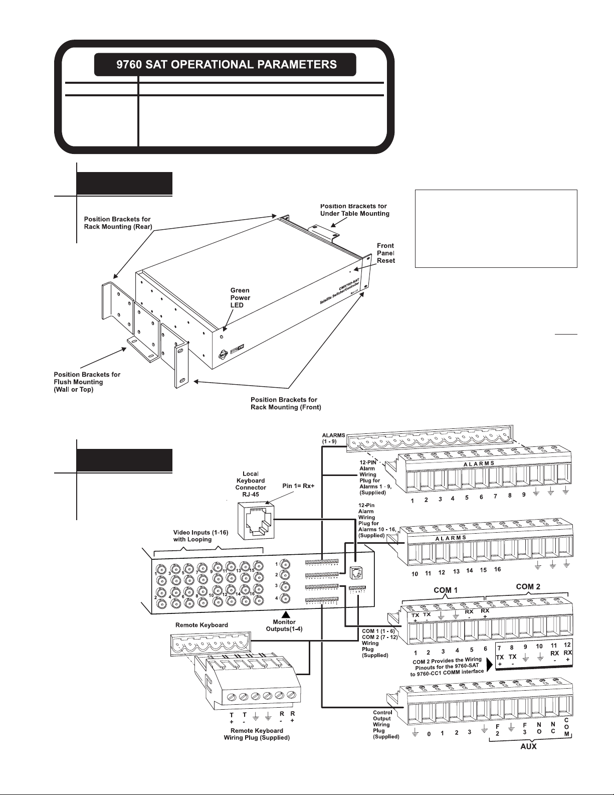
The CM9760-SAT is a sequential video switcher
for use as a Satellite Control System of the
CM9760 system. Below are shown the front and
rear views, the mounting geometry and, for reference, the pinout designations for all connectors on the unit. The four, 12-pin and one, 6-pin
wiring plugs (shown in Figure 2) are supplied
with the unit. Especially note the COM 2 connector designations. Required software version
levels and other Comm parameters are given
in the information box to the left.
• Observe the precaution outlined
in the NOTE below.
• Orient unit as required.
• Mount as deemed appropriate
to your installation.
NOTE:
Factory default, video input termination is 75-ohm, non-looping. If you want the
loop-thru option active for any video input, the
top cover of the unit must be removed to make
the change
Video Inputs
(see Section 1,
).
You may want to do this before
3.2.1, Looping
rack-mounting the unit.
FIGURE 1
CM9760-SAT Front View, Including Mounting Geometry
R E A R
FIGURE 2
CM9760-SAT Rear View
INTRODUCTION CM9760-SAT i
Page 5
MANUAL NOTES
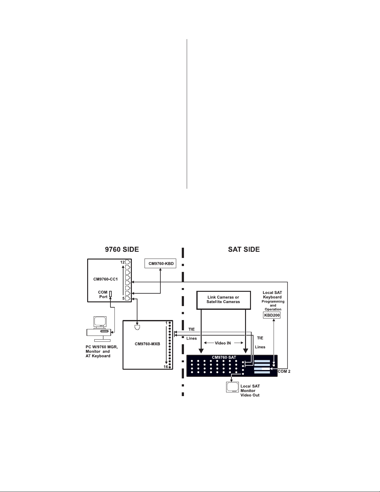
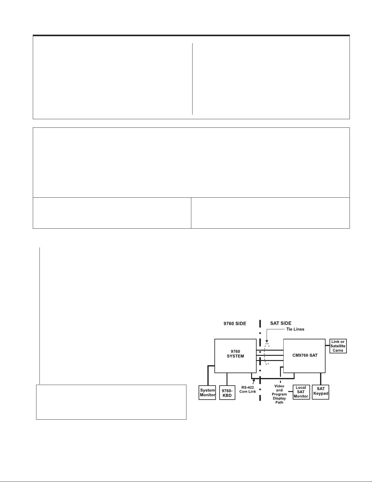
1. The approach used in this manual is predicated on the installation
and operation of the CM9760-SA T in a 9760 System environment.
Figure 3 is a block diagram that represents such an environment.
2. Figure 3 is our reference or “jumping-off” point for most discussions
in this manual. Note that the block diagram is divided in half: one
side is labeled the “9760 SIDE” and the other is labeled the “SAT
SIDE”. For each, we discuss installation, programming, configuration, and operation, in the order listed in the MANUAL DIREC-
TORY on the next page.
3. The KBD200, KBD300, and KBD300V are keypads that connect to
the SAT SIDE in our sample system environment where they are
used for local operation and programming of the CM9760-SAT.
A section on keypad operations, separate from their actual use in
a programming or operational situation, is not included in the main
body of the manual. This is done to minimize the interruption that
would be involved in flipping back and forth between a section on
the mechanics of keypad operation and the discussion at hand.
Every effort is made to include all data needed to carry out a proposed operation or programming function at the point where it is
discussed or used in the manual. However, we do provide, in Appendix III,
KBD200/KBD300/KBD300V keypad layout and button description.
Keypad Definitions and Templates,
FIGURE 3
9760-SAT System Environment
an abbreviated
4. Extensive discussions of keyboard and keypad connections (other
than local SAT keypad hookup) are not included in the main body
of the manual. For example, although multiple keypads can be connected to the SAT, you will not find a two-page digression in the
middle of the manual on how to do it. Multiple keypad hookup is
covered in Appendix II,
attempt to minimize blanket statements like “connect a straight-wired
cable at one point”, or “connect a reverse-wired cable at another”,
and, instead, encourage you to determine the parameters of cable
hookup to your own satisfaction. Overt statements like those just
mentioned are based on assumptions that may not be true for your
on-site situation. When installing a supplied cable yourself, you
should not blindly attach the cable (supplied or on-site) without knowing that the connection you make should work. In fact, you should
be surprised if it does not work. Specific instructions and suggestions on matters related to keypad hookup and communication wiring are found in Appendix I,
Tutorial
and Appendix II,
just a few pertinent facts at your disposal in order to connect 9760
communication devices together correctly.
Remote Keypad Connections
. Similarly, we
Communication and Connection
Remote Keypad Connections
. Y ou need
ii C1510M-A (2/03) INTRODUCTION
Page 6

MANUAL DIRECTORY
INTRODUCTION iv
SECTION 1 1-1 Physical Installation
This section describes the physical installation of communication and video lines necessary for SAT
system operation. Instructions for connecting additional equipment, necessary for proper operation at
the local SAT SIDE, are also discussed. The choices made here are reflected in the configuration of
the applicable programming menus (SAT SIDE) and flat files (9760 SIDE), which are covered in
Section 2.
SECTION 2 2-4 Programming and Configuration
SAT programming menus are discussed first.
NOTE:
These menus are normally programmed via a local keypad connection on the
system. They can also be programmed from the
accomplish these tasks are possible. Whether you program from the local
9760 SIDE
tem
, depends upon choices made about your particular equipment configuration. How
these setups affect your choice of programming vehicle is discussed in Section 2, PRELIMINARIES.
Next, other programming functions related to local SAT operation are discussed (presets, patterns,
zones and so on).
This section concludes with a discussion on how to program the 9760-MGR (System Manager) configuration or “flat” files for proper operation of the 9760-SAT link.
SECTION 3 3-1 Operation
SAT operation on the local SAT SIDE of the system is discussed first. These include keyboard acti-
vated functions for camera/monitor selections and control operations for other functions including sequence, pattern, and zone operations, as well as the control of auxiliaries.
Locally activated alarms on the SAT SIDE lead to discussions of 9760 System-SAT alarm responses.
Alarm response, in turn, leads to a discussion on how different equipment configurations are integrated
into the 9760 system as a whole. You may have only one SAT, or perhaps two SATs, or one SAT and
a 9760-ALM unit, or two SAT units and an ALM unit.
Alarm responses for the 9760-ALM unit are structured differently from that of the SAT unit, yet both use
the same Alarms system configuration file. How it actually works is discussed here.
9760 SIDE
SAT SIDE
of the
via a 9760-KBD. A number of ways to
SAT SIDE
or from the sys-
SECTION 4 4-1 System and Multiplexer Example
A basic 9760-SAT system example that demonstrates the basics of system hookup and programming is
considered. The example is dissected in a step-by-step, detailed manner. At each step, the hookup and
programming functions affecting that portion of the system are discussed. References to applicable
manual sections are given where appropriate. The basics of integrating a Genex multiplexer into a 9760SAT system environment is also discussed.
4-11 Multiplexer Example
SECTION 5 5-1 Appendices
A short tutorial on device interconnections is given. Keypad definitions, templates and remote keypad
connections are followed by a listing of SAT models and associated equipment. We round out the
section with a menu-listing of SAT Programming Default Reset parameters and a connector pinout list
for all devices used in the manual.
SECTION 6 6-1 Miscellaneous
6-1 Safeguards and Warnings
6-2 Specifications
6-3 Index
6-5 Regulatory Notices
6-5 Warranty
INTRODUCTION CM9760-SAT iii
Page 7

INTRODUCTION
Physical
Description
The SAT-9760
Relationship
Setup
Overview
The CM9760-SAT is a 16 X 4 (16 camera input by 4 monitor output) cross-point video matrix, sequential
switcher.
The physical appearance of the 16 X 4 SAT is dominated by the 16 video inputs (and corresponding
loop-thru BNCs) on the rear of the unit. Four BNC monitor-outs (for local or tie line use), four 12-pin
wiring plugs for other functions and, finally, local and remote keypad ports round out the device connection list. Aside from confirming whether or not loop-thru operation is part of your configuration, the unit
is ready to be rack-mounted. Remember: there is no “ON/OFF” switch and therefore the unit should not
be plugged in until all connections to it have been made.
Although the SAT is a peripheral device of the 9760 system, it is unique in that a considerable amount
of local programming and control freedom can exist at the downstream or SAT SIDE of the configura-
tion. Y ou can think of the SAT as capable of performing many of the functions normally associated with
a single node of the 9760 system. This analogy extends to include programmed SAT alarm-event
notifications to the 9760 system. In some configurations, you might want to ignore local SAT functions
altogether and use all monitor-out lines as tie lines back to the main system.
To enable operation of these functions, the following tasks must be performed:
1. Physically, the SAT and the 9760 system communicate in full duplex mode via an RS-422 Com
link between the CM9760-CC1 and the port provided on the SAT. Those SAT monitor-out lines
(configured as tie lines), must be run back to the 9760 SIDE and connected as video inputs to the
matrix bay and those monitor-outs not configured as tie lines must be configured for LOCAL use.
2. In addition to physical hookup, configuration files must be programmed on the 9760 SIDE to
make the 9760 aware of the SAT’s existence and to condition tie line connect points. The informa-
tion box found at the beginning of this manual lists the minimum version levels of software needed
by equipment on both sides of the configuration to operate the 9760-SAT system interface.
3. By far, the majority of programming occurs on the SAT SIDE and serves a dual purpose. The first
is to condition the SAT-9760 interface, in particular, the tie line link(s) between the 9760-MXB
and the associated monitor outputs on the SAT. This is accomplished through programming the
applicable entries in the SAT’s Monitor menu. Other menus (for example, those that set up
communication port attributes) are affected as well. The second purpose involves programming
all associated link cameras, monitors, alarms and other connections for PTZ functions and other
SAT sequential switcher operations for use at the local level. Local programming and operation
of the SAT and associated link cameras are controlled by desktop keypads (the KBD200, KBD300
or KBD300V).
iv C1510M-A (2/03) INTRODUCTION
Page 8
SECTION 1 PHYSICAL INSTALLATION
1.0 COM CONNECTION ....................................................... 1-1
9760 SIDE
CC1 to Wall Block ............................................................. 1-2
SAT SIDE
Wall Block to SAT ............................................................. 1-2
2.0 VIDEO TIE-LINES ........................................................... 1-2
9760 SIDE ........................................................................... 1-2
SAT SIDE ............................................................................. 1-2
3.0 ADDITIONAL SAT CONNECTIONS ............................ 1-3
Local Monitor ................................................................. 1-3
Link Cameras....................................................................... 1-3
Looping Video Inputs ..................................................... 1-3
Receivers ....................................................................... 1-4
Alarms............................................................................ 1-4
Auxs ............................................................................... 1-5
Local Keypads ............................................................... 1-5
1.0 COM CONNECTION
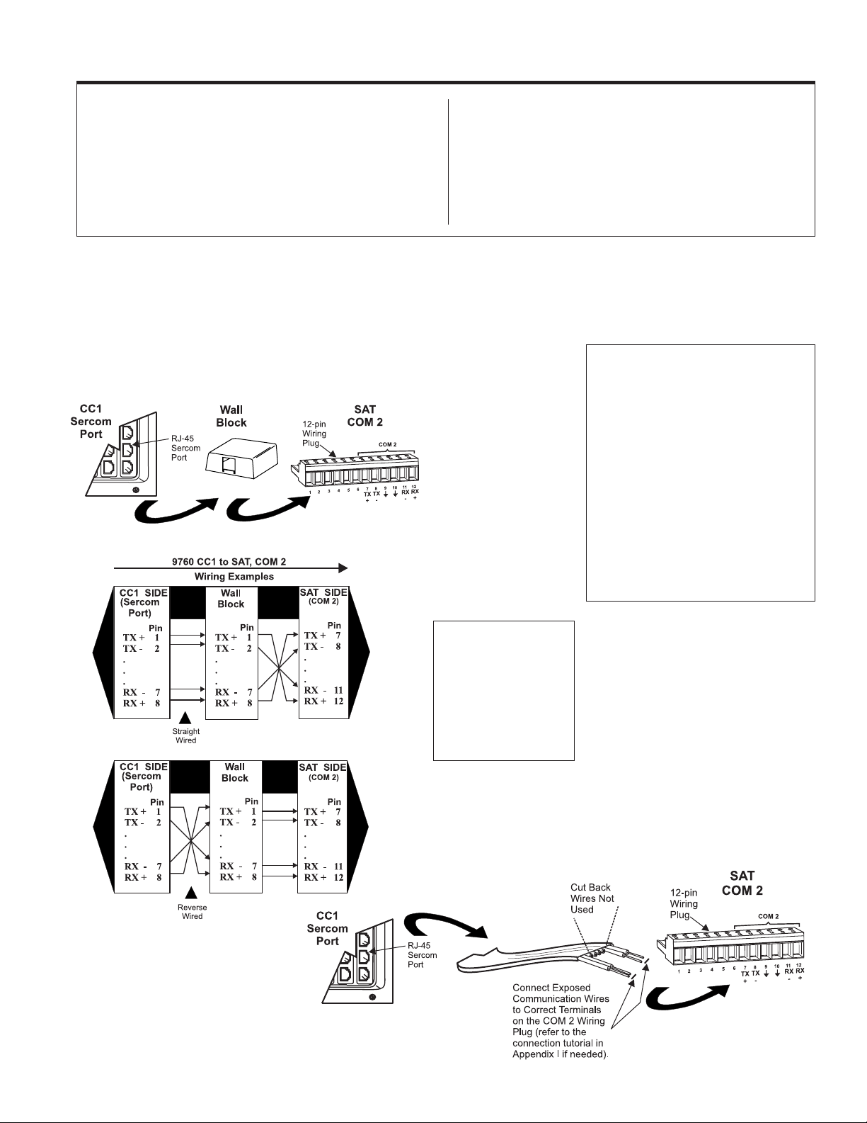
The COM connection between the CM9760-CC1 and the CM9760-SAT runs from an available sercom port** on the rear of the CC1 to appropriate
pinouts located on the wiring plug for COM 2 on the SAT. A physical disparity exists between the RJ-45 connector on the CC1 SIDE and the 12-PIN
wiring plug on the SAT SIDE. An intervening wall block can be used (normally placed at the SAT SIDE) to facilitate the connection.***
NOTE:
Figure 1-1
CC1 to SAT Interface
The RJ-45 wall block, represented in Figure 1-1, can be obtained by ordering a Pelco
“KBDKIT”. In many cases, however, an
SAT
sys-
tem order will include several key-
pads in order to accommodate
more than one operator on
the
SAT SIDE
. Multiple keypads are wired via the remote- keyboard, wiring plug.
In order to provide power to
the keyboard, a KBDKIT,
which includes a transformer,
is required, as power is not
provided at the remote port
itself. The kit, however, contains two wall blocks. Only
one wall block is needed to
wire the keypad. The “spare”
could be used here.
**
SATs
received in a system order are
assigned connection locations that are
found on your included port assignment
sheet(s). These indicate the CC1 Sercom
port to connect your
If you are adding the
system, you must
SAT
SAT
FIRST
to.
to an existing
do an acrossthe-board check of your system software
to ensure it is compatible with the version
levels required for satellite operation. The
information box on the first page of this
manual (
eters
9760 Operational Param-
) indicates the minimum version
levels of software required for satellite operations. If necessary, upgrade your associated system and peripheral software.
Figure 1-2
Alternate CC1 to SAT Interface
***
An alternate method
is to strip the 8-conductor,
flat communication cable
to expose the necessary
communication wires and
then wire directly to the
wall plug, eliminating the
need for the wall block
(see below).
PHYSICAL INSTALLATION CM9760-SAT 1-1
Page 9
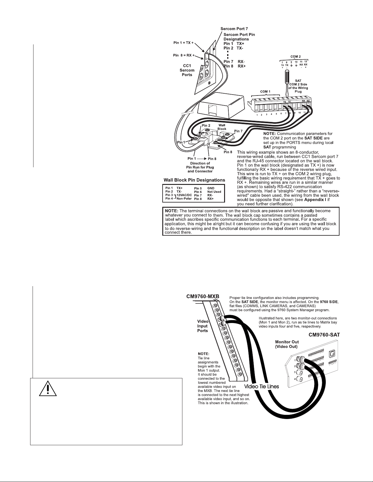
1.1 9760 SIDE – CC1 TO WALL BLOCK
1. Determine the cable type (straight or reverse)* that
is provided or exists on-site that you want to use
between the RJ-45 Sercom connector on the CC1
and the wall block.
*see Figure 5-1 in Appendix I
2. Make the connection using Figure 1-3 as a guide.
1.2 SAT SIDE – WALL BLOCK TO SAT
1. Depending on the cable type used, wire the wall
block-to-SAT connection based on Figure 1-3 and
the included pin designation table. The 12-position wiring plug can be removed from the unit for
easy wiring access.
2. Strip and insert each wire to be connected in the
provided slot. Tighten firmly with a straight-slotted
screwdriver as shown.
Figure 1-3
Wall Block Connections
NOTE: The Comms configuration file in the
MGR program is used to set communication
parameters for the SAT connected to the
Sercom port (see SECTION 2, 3.1 COMMS
Files).
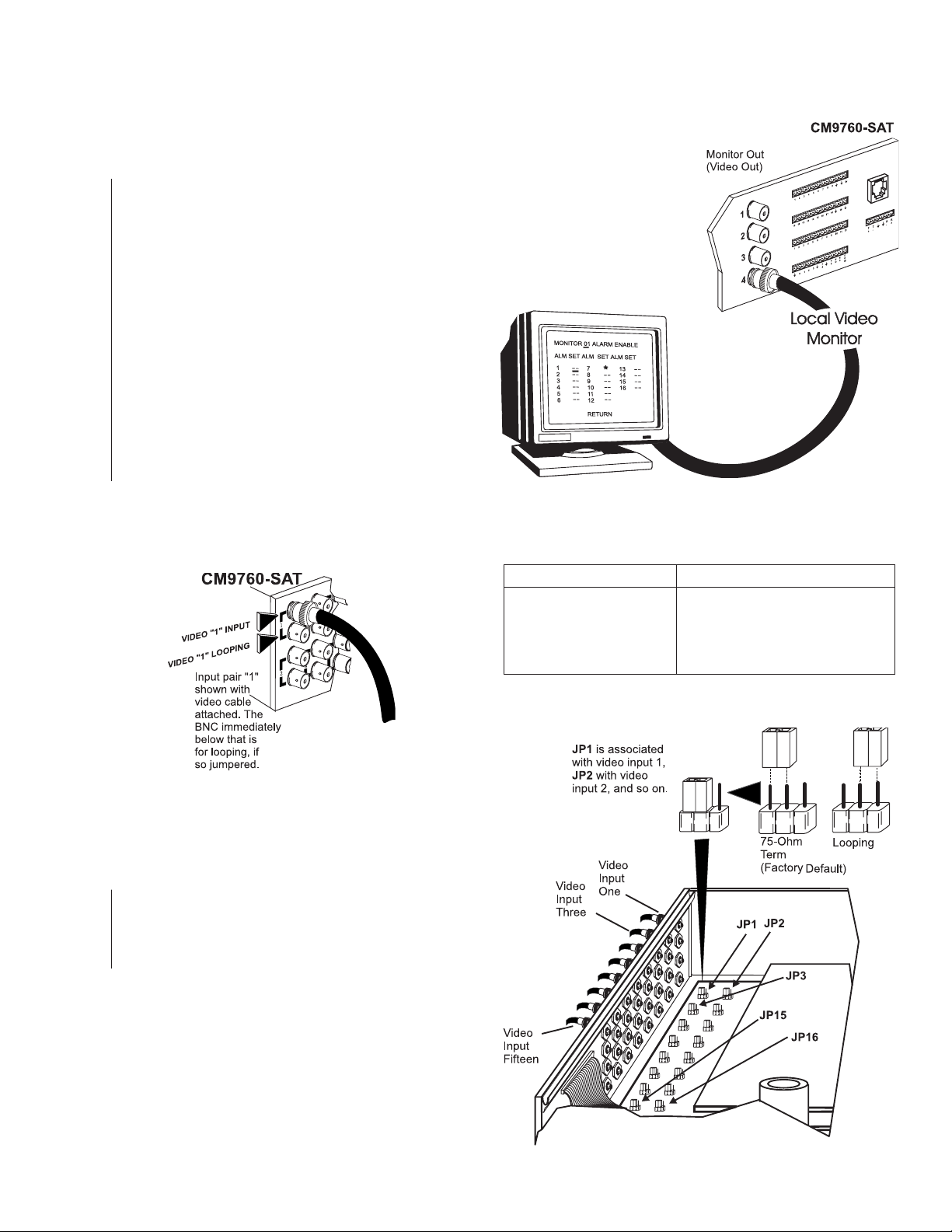
2.0 VIDEO TIE LINES
In order for the SAT to fulfill its function as a Satellite of the 9760 system, video interconnects, in the form of tie lines, must be run between the SAT
and the CM9760-MXB. The tie line–there must be at least one–has several uses. One function is to serve as a pathway for 9760 operators who want
to call up satellite camera displays via their 9760 system keyboards. The other is to provide a pathway for the programmed display (on 9760-system
monitors) of alarm-activated link cameras located on the SAT SIDE of the configuration.
2.1 9760 SIDE
The video tie lines coming from the SAT are connected to avail-
able, video input BNCs on the CM9760-MXB unit (see the NOTE
in Figure 1-4). Specifically note the physical port to which each
tie line is connected. You need this information later, when the
Cameras and Link Cameras configuration files (flat files) are programmed on the 9760 SIDE of the configuration. These inputs
are treated differently so that they are recognized as tie lines and
not just regular video inputs.
2.2 SAT SIDE
You must also allocate at least one monitor-out on the SAT SIDE
of the configuration to tie line use. In most instances, you also
need one monitor-out for local SAT operation and programming.
IMPORTANT NOTE:
tor-out use is under user control, subject to the condi-
tion that at least one tie line exists and that the following
rule for multiple tie line hookup is obeyed: If you use
it must be connected to the
lines, they must be connected to the
monitor-outs, and so on.
sequential, ascending order to the monitor-outs on
the SAT. You may not “skip” around.
monitor-out for
LOCAL
use until all tie lines are configured first.
The ratio of tie line to local moni-
one
tie line,
MON 1
BNC. If you use
MON 1 and MON 2
Tie lines must be connected in
two
tie
BNC
Never configure a
Figure 1-4
Video Tie Line Hookup
1-2 C1510M-A (2/03) SECTION 1
Page 10
3.0 ADDITIONAL SAT CONNECTIONS
If you want to operate and program from the local SAT SIDE of a
system configuration, a number of additional devices and connections
remain to be made. In order to view the results of local operations and
program SAT menus, a local monitor is needed.
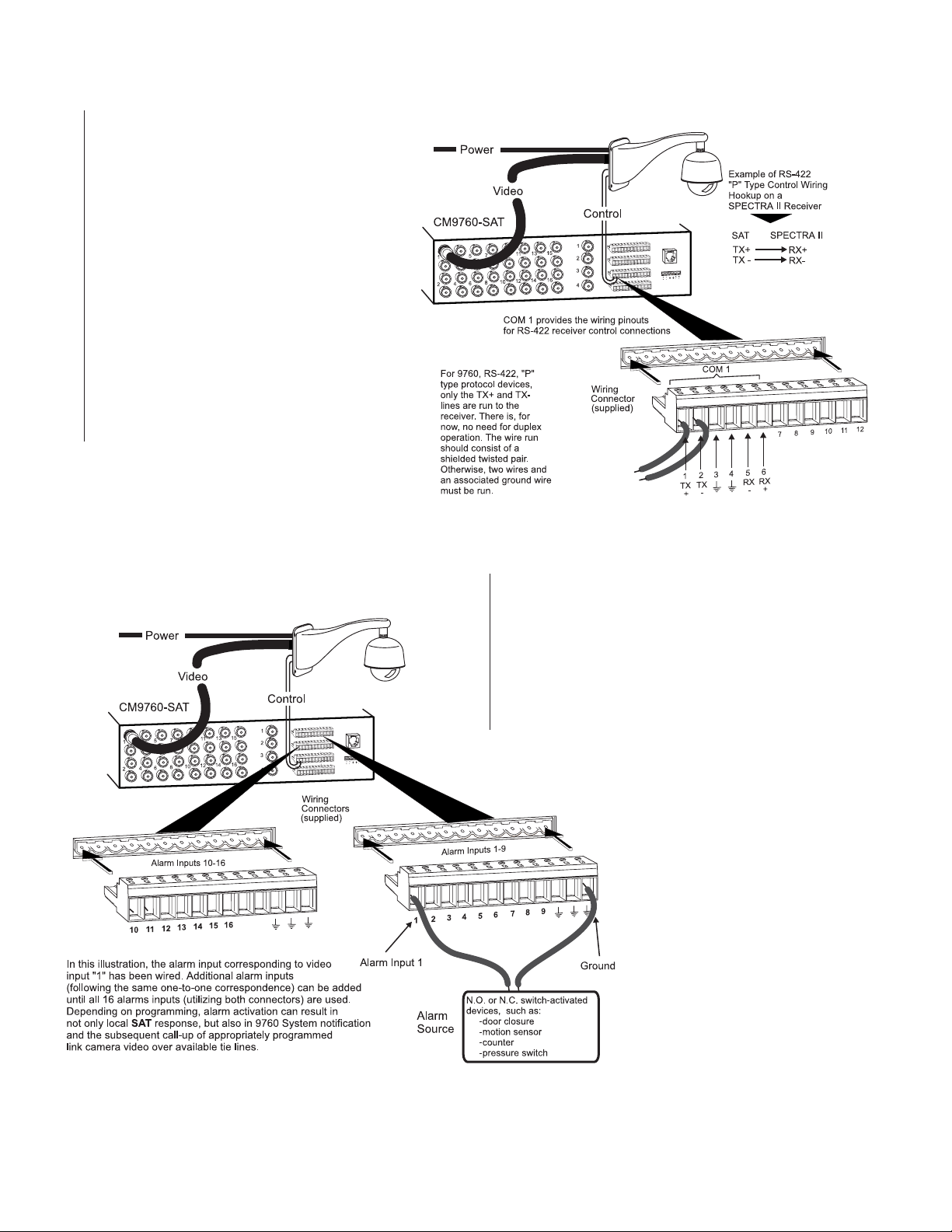
3.1 LOCAL MONITOR
The local Monitor is used to display link camera call-ups and
switcher functions for local SAT operations. It is also used to
display the main program menu and its sub-menus during SAT
programming and setup. To install the local monitor:
1. Install the monitor.
2. Run a video output from the SAT to the installed monitor.
3.2 LINK OR SATELLITE CAMERAS (VIDEO INPUTS)
The CM9760-SAT can accommodate 16 video inputs that are
individually jumper-selectable for terminated or looping operation. All video inputs are set to 75-ohm termination at the factory.
See Table A for typical coaxial video cable and recommended
distances. Use only coaxial cable specified for CCTV systems.
Run the video cables from the cameras or camera receivers to
the selected video inputs on the rear of the CM9760-SAT (the top
connector for each input pair).
Figure 1-5
Local SAT Monitor
Local SAT operation and control
functions are displayed here,
including the menus for SAT
programming. You should have
at least one local display available
to monitor local operations.
Depending on your application,
you can have up to three monitor-outs
configured for local use. Monitor functions
are chosen during programming
(see Section 2, Monitor Programming
Menu–page 2 of 3).
NOTE: If all monitor-outs
are set up as tie lines, SAT
menu programming is done
from the 9760-KBD.
Figure 1-6
Link (Satellite) Camera Inputs
3.2.1 Looping Video Inputs
As stated at the beginning of this manual, the loop-thru option is available for each video input. If you want this option for any input, remove
the top cover of the unit and reposition the jumpers according to the
information provided in Figure 1-7.
Video Coaxial Cable Requirements
Table A
Cable Type Maximum Distance
RG-59U 750 ft. (228.6 m)
RG-6/U 1,000 ft. (304.8 m)
RG-11/U 1,500 ft. (457.2 m)
Consult factory Above 1,500 ft (457.2 m)
Figure 1-7
Loop-through Configuration
PHYSICAL INSTALLATION CM9760-SAT 1-3
Page 11
3.3 RECEIVERS
If any camera you want to install is PTZ capable, then the receiver for that camera must be
individually wired for power and control (dependent on type). The CM9760-SAT has built-in
software that is individually selectable for each
camera control type. The correct protocol is selected via menu choices when programming the
Cameras menu for each individual input (see
Section 2,
2 of 2
able to utilize one of two communication protocols for connection to the SAT. One control type
is Coaxitron®. Coaxitron (standard or extended)
receivers utilize the input video line as a path
for sending control commands to the receiver.
The other control type is RS-422 “P” protocol
receivers that are wired independent of the
video path. RS-422 command control connections originate at COM 1 o n the rear of the SAT
(see Figures 1 and 1-8).
Camera Programming Menu-Page
). Allowed camera control types must be
Figure 1-8
Receiver Wiring and Control
Figure 1-9
Alarm Wiring
3.4 ALARMS
The SAT has 16 alarm inputs, each designed for use with standard
single-pole, single-throw (SPST) switches. The alarm inputs on the
connector correspond, on a one-to-one basis, to the SAT’s 16 video
inputs; that is, video input 1 corresponds to alarm input 1, video
input 2 corresponds to alarm input 2, and so on. To properly recall
alarmed video, each alarm connection must correspond to the correct video input. Each must also be appropriately programmed for a
number of variables. Refer to Section 2,
Alarm Programming
Menu-Page 1 of 1.
Connect the alarm inputs as illustrated in Figure
1-9. Alarms 1-9 use the indicated 12-pin connector (provided). For each alarm-video pair installed and accounted for, wire a return ground
path. Utilize a ground connection located on the
same connector on which your alarm input is
wired. Proceed on a pair-by-pair basis until all
video-associated alarm pairs are wired. Utilize
both alarm wiring connectors, if necessary.
1-4 C1510M-A (2/03) SECTION 1
Page 12
3.5 AUXS
There are three AUX outputs available through the control output wiring terminals located on the rear of the SAT. Aux operation and control are
for local SAT SIDE use only. Aux ouputs cannot be controlled from the 9760-KBD. These outputs are used to operate external devices. Each
output corresponds to a function key (F1-F3) on the KBD200/300/300V keyboard. The outputs can also be programmed to respond automatically to alarms. F1 is a Form C relay wired with a common (COM) and a normally open (N.O.) or normally closed (N.C.) contact. The other two
outputs (F2 and F3) are open collector transistor drivers that drive TTL circuits or low-current relays. If you use an external relay, make sure that
voltage and current requirements are well below maximum ratings. Exceeding specified values can permanently damage the transistors.
During programming, configure the auxiliary outputs to agree with the type of equipment you are using. Refer to Section 2,
Auxiliaries
Programming Menu-Page 1 of 1.
Follow the examples illustrated in
Figure 1-10 for wiring up the F1,
F2 and F3 relay contacts. The instructions for wiring the F3 relay
are the same as those illustrated
for F2, if you substitute pins 8 and
9 for pins 6 and 7. When you finish wiring the auxiliary outputs,
plug the wiring connector into the
control outputs terminal strip.
Figure 1-10
Aux Connections
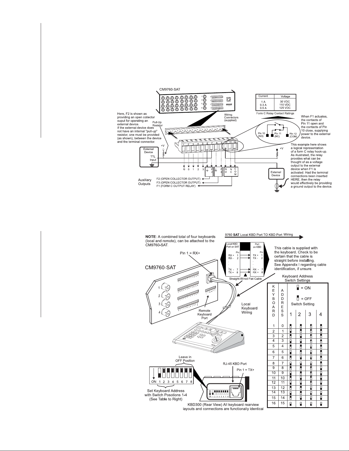
3.6 LOCAL KEYPADS
The KBD200/300 may be connected to
the local keyboard port on the SAT and
used (in conjunction with the local monitor) for local SAT operations and program-
ming. The KBD300V cannot be used with
the local keyboard port as the matrix display is not compatible with the voltages
supplied there. Connect the keyboard to
the local SAT keyboard port as indicated
in Figure 1-11. Additional keyboards may
be connected to the SAT unit using the
remote keyboard port (see Figure 1 and
reference Appendix II for information
on wiring the remote port).
Figure 1-11
Wiring the Local Keypad Port
PHYSICAL INSTALLATION CM9760-SAT 1-5
Page 13

(This page intentionally left blank.)
1-6 C1510M-A (2/03) SECTION 1
Page 14
SECTION 2 PRELIMINARIES
PRELIMINARIES ...................................................................... 2-1
1.0 SAT MENU PROGRAMMING ........................................ 2-5
PROGRAM MODE
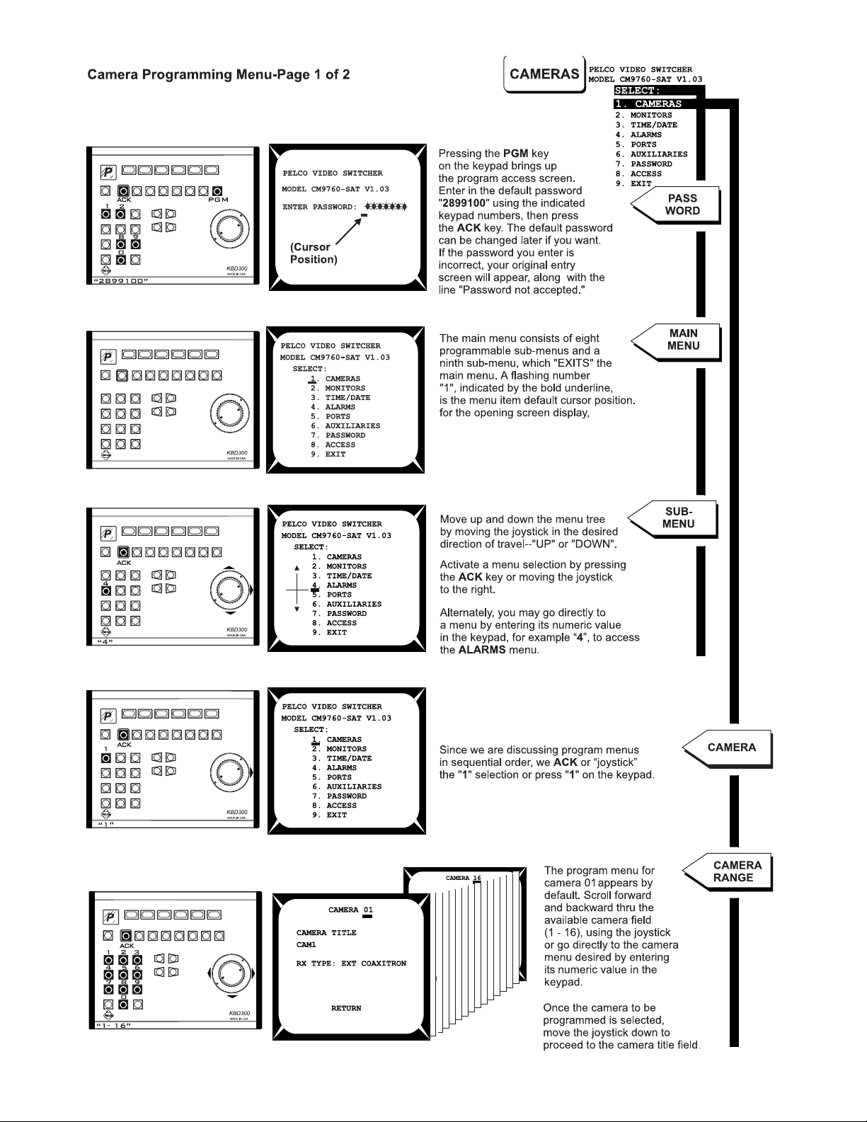
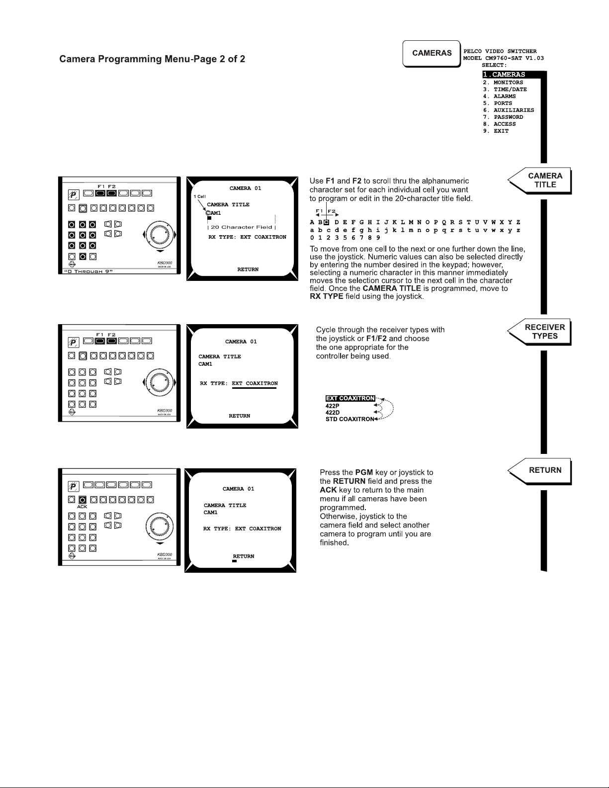
Camera Programming Menu............................................. 2-6
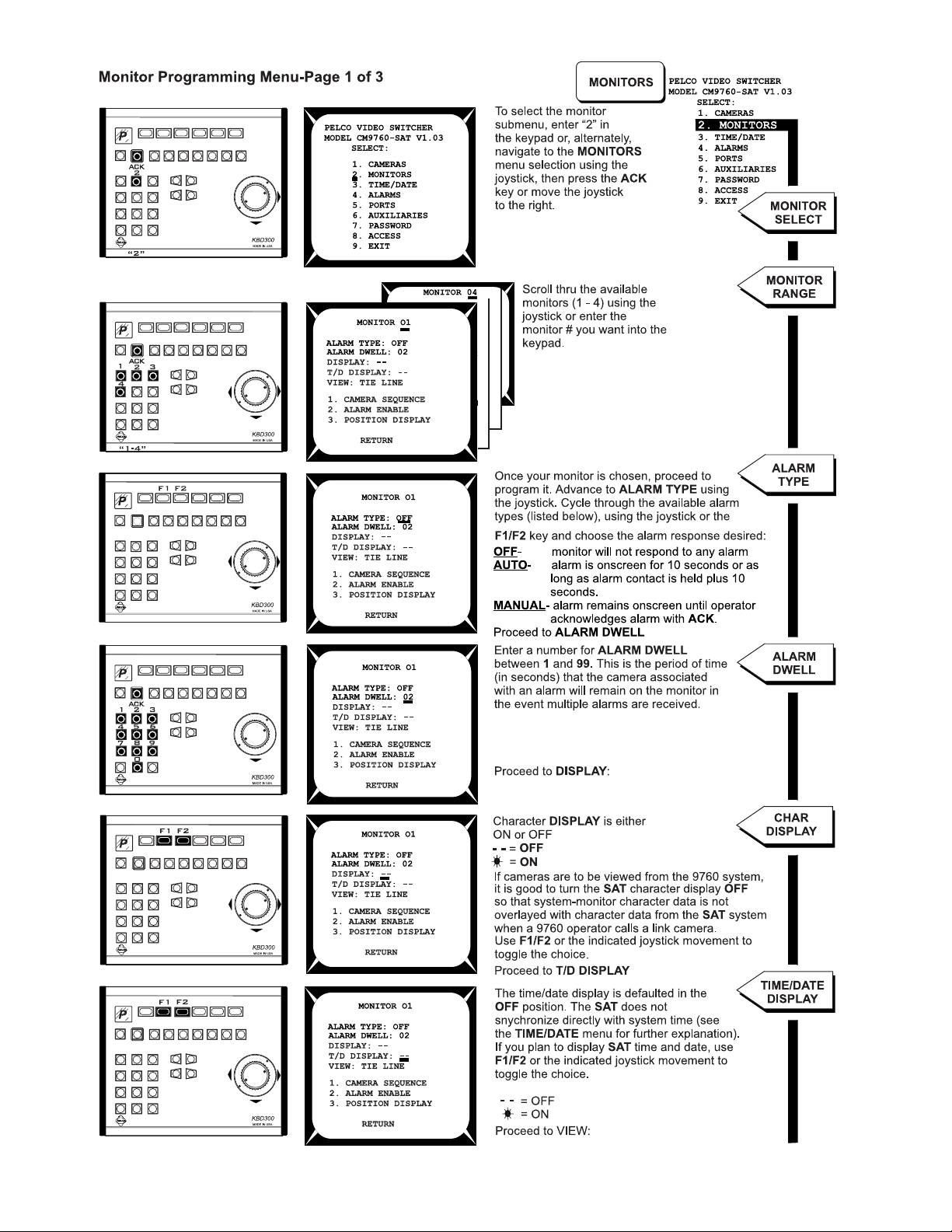
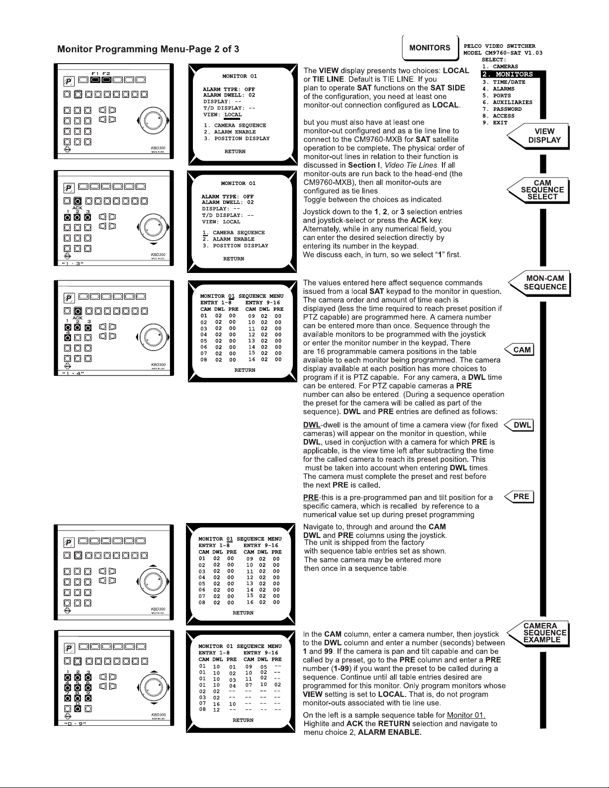
Monitor Programming Menu ............................................. 2-8
Time-Date Programming Menu....................................... 2-11
Alarms Programming Menu ............................................ 2-12
Ports Programming Menu ............................................... 2-13
Auxiliaries Programming Menu ....................................... 2-14
Password Programming Menu........................................ 2-14
Access Programming Menu............................................ 2-15
You can program the CM9760-SAT from the SAT SIDE, using a local
keyboard and monitor, or you can program the SAT from the 9760
SIDE, using a 9760-KBD and a system monitor assigned to that operator. These two basic programming methodologies are not, however,
mutually exclusive. By that, we mean, choosing to program from one
location does not necessarily exclude programming from the other. Intermediate variations to programming on just one side or the other are
possible.
NOTE:
The illustrations in this section represent the functional relationships of the equipment mix needed to accommodate each programming choice that is discussed in the associated text.
2.0 OTHER SAT PROGRAMMING .................................... 2-16
OPERATIONAL MODE
Presets............................................................................ 2-16
Patterns........................................................................... 2-17
Zones .............................................................................. 2-18
3.0 9760 MGR-SAT PROGRAMMING .............................. 2-19
PROGRAMMING MODE
Comms File..................................................................... 2-19
Cameras File .................................................................. 2-20
Link Cameras File ........................................................... 2-20
Alarm File........................................................................ 2-21
Interspersed with these programming setups is the need to integrate
what is going to be programmed where, and by whom, given the various
configurations of equipment possible. In the illustrations and explanations below, we discuss some of these variations and indicate advantages, disadvantages and/or tradeoffs, if they exist, of each. We also
describe how to reach the main SAT programming menu from the given
programming location.
There are essentially three basic programming configurations. After we
look at those, we discuss a program variation.
NOTE:
In those instances where we discuss procedures or actions
yet to be covered in the manual, we either give a sufficiently adequate
(but abbreviated) discussion, or refer you to the appropriate manual
reference.
1. Programming Configuration I – Program the SAT from the SAT SIDE only.
This choice implies that at least one monitor-out line on the SAT SIDE is utilized as a local monitor and that you have a keyboard connected to the
SAT for programming purposes (see Figure 2-1).
(a) Initialize the keyboard to your local monitor (see Section 2,
(b) Press the PGM key on the KBD200 or 300.*
(c) Enter the password (default 2899100) and press the ACK key. This activates the main SAT programming menu.
Advantages:
accessible on the SAT SIDE of the configuration. The system user
can call up link cameras. Local SAT alarms can be viewed locally
and/or automatically reported to the system user. Associated SAT
alarm camera displays can be placed on tie lines for viewing on
system alarm monitors (this is the primary configuration that we
use when discussing SAT configuration, operation and program-
ming). It encompasses all the elements that the SAT is designed to
use and avoids programming from the system side, which is less
efficient.
Disadvantages:
eration and programming means someone must be stationed at
the satellite location to fully utilize its functions. If you are interested
only in alarm notification back to the system, you have, at most,
only three tie lines available, instead of four.
Local control and alarm notification operations are
From a system user viewpoint, local SAT op-
1.0 SAT MENU PROGRAMMING)
Figure 2-1
Programming Diagram One
*Although the KBD300V can be used for programming, we don’t
mention it here because (1) it can only be hooked up using the
SAT
keyboard remote port and (2) it requires a dedicated local
monitor-out line for its LCD display. The KBD300V is discussed in
APPENDICES II and III.
PRELIMINARIES
PROGRAMMING AND CONFIGURATION CM9760-SAT 2-1
Page 15
2. Programming Configuration II – Use the same configuration and program the SAT from the 9760 SIDE.
The same equipment diagram used above is applicable here. Here, a
conscious choice is made to the program from the 9760 SIDE rather
than the SAT SIDE. If you want, programming chores can be split
between either side, although that is not recommended.
(a) Ensure no one else on the 9760 SIDE is using an SAT tie line.
(b) Ensure that the following items are in place:
1. The Link camera you plan to call** should already be included in the programmed Link Cameras file of the System
Manager (see Section 2,
2. The tie lines coming from the SAT to the MXB on the 9760
SIDE should be identified and programmed into the System Manager’s Cameras file (see Section 2,
eras File)
(c) From the 9760 KBD, call up any link camera programmed in the
Link Camera file (see Section 3,
Cameras)
**
A link camera must be called as part of the programming process here. It is not necessary that the camera called be connected to the
.
.
3.3 Link Cameras File)
2.1 Selecting Link [Satallite]
.
3.2 Cam-
(d) Proceed to the DEF (define) sub-menu. (You may need to press
the ESC key first, then press the DEF key). If this is the first time
accessing that menu, enter the PIN (default 1234).See Figures
3-20 and 3-22 in Section 3,
3.2 9760 System-SAT Alarm Re-
sponse.
(e) Next, enter 89 into the 9760 keypad and then press the PRST
key (while still within the DEF menu). The main programming
menu of the SAT appears on the monitor in front of you.
Advantages:
the benefits of local SAT operation; therefore, someone not able to
program the SAT could, at least, operate SAT SIDE functions.
Disadvantages
SIDE, you must ensure that no one, other than the programmer, is
calling up any link cameras or otherwise utilizing any tie lines connected to the SAT. It’s possible for the SAT programming menu to
inadvertently appear on their monitor instead of the programmer’s
monitor.
You can program from the system side without losing
: Before initiating programming from the 9760
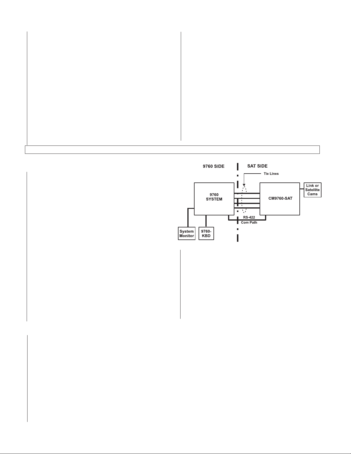
3. Programming Configuration III –
Programming from the 9760 SIDE only.
The programming setup for this configuration is illustrated in Figure
2-2. Note that all monitor-outs on the SAT SIDE are used as tie lines
that go to the 9760 SIDE.
With this configuration, the minimum hardware requirements before
programming can begin are as follows:
a. Monitor-outs from the SAT (tie lines) are connected to available
video inputs on the matrix bay on the 9760 SIDE (see the
“NOTE” about tie line connection in Section 1,
Lines
).
b. The COM line between the two pieces of equipment is in place.
c. You have a list of camera attributes for those cameras/receivers
that are or will be attached to the SAT. It is not necessary for
them to be physically attached to the SAT for programming to
be possible. When attached, however, the programmed attribute
for that input must correspond to the equipment connected.
d. The SAT is powered ON (plugged in).
e. The items listed in step 2b of the previous programming con-
figuration (the Comms, the Cameras and the Link Cameras con-
figuration files) are programmed and integrated into the 9760
System.
2.0 Video Tie
Figure 2-2
Programming Diagram Two
Once the 9760 System is initialized using the configuration files just
mentioned, you can proceed to program the SAT.
f. Repeat steps 2c, 2d, and 2e of Programming Configuration II.
Advantages:
system. All programming is done from the 9760 SIDE. The number
of tie lines available for operator access from the 9760 SIDE of the
configuration is at a maximum.
Disadvantages:
pabilities back to the head-end. Local satellite SAT SIDE operations
are not possible.
No operator is required on the SAT SIDE of the
You only use the SAT for its alarm reporting ca-
SAT
.
4. Unconventional Programming Configurations
Here we want to make some comments and put forth some suggestion about how you might use variations to the previous programming
configurations based upon how the 9760-SAT interface works. The following observations and general statements can be made:
1. As long as there is one tie line and a Com line in place between the SAT and the 9760 System, all attributes of SAT configuration can be
programmed from the 9760 SIDE via a preset call.
2. Normally, you should not initialize a keyboard (SAT SIDE) using a monitor-out line that has been configured as a tie line. However, under
certain circumstances, you might want to do this. The result of this action (from the SAT SIDE’s point of view) is that a monitor on the 9760
SIDE is used as a “substitute” local monitor for programming the SAT. The programming itself, however, is done from the 9760 SIDE.
Doing this allows one to program from the 9760 SIDE without using a preset call. Unfortunately, this can only be done if the operators on
both sides of the configuration can physically talk to each other during the programming process because the SAT SIDE must initiate and
exit the programming mode based on queues received from the 9760 SIDE.
3. Each side of the 9760-SAT configuration can be programmed independent of the other. Neither has to be physically connected to the other
for programming to be done as long as the programmed parameters of each match the physical parameters of the final equipment configu-
ration. System 9760-SAT related files (Comms, Link Cameras and Cameras) are programmed only from the 9760 SIDE of the configura-
tion. SAT menu software, however, can be programmed from either side of a configuration.
2-2 C1510M-A (2/03) SECTION 2
Page 16
4a. Programming Variation Example: 9760-SAT Programming Minus Preset Call
This scenario illustrates the situation referenced in point 2, above.
The rationale for using this variation might be:
The local SAT programmer is not sure of the correct parameters to enter; or,
The local SAT programmer wants certain aspects of an operational or reprogrammed SAT to be checked by supervisory personnel located
on the 9760 SIDE of the configuration; or,
The programmer on the SAT SIDE might be unavailable; no one on the 9760 SIDE remembers the preset call function or remembers how
to use it, and so on.
Proceed as follows:
1 From the 9760 SIDE, ensure that no one, other than the person doing the programming, is using a tie line for any purpose.
2. Call up a satellite camera to a viewable system monitor. Use the logical number for the referenced camera.
NOTE:
The operator on the
NOTE:
It is not necessary for the called camera to actually be attached on the
9760 SIDE
and on the
SAT SIDE
must have some independent means of communicating with each other.
SAT SIDE
.
All you are doing here is tying up a tie line to your
reference monitor so that anything put on the tie line can be viewed from that display.
a. Initialize or reinitialize (as the case may be) the KBD on the SAT SIDE; use a monitor-out number that has been allocated
as a tie line.
NOTE:
More than likely, you would use MON 1, as the object here is to match the monitor -out line initialized on the
SAT SIDE
video tie line secured or referenced on the system side in step 2. The 9760 system normally grabs the first tie line available. Since no
tie lines are allocated for use but the one we called, it should be the one connected to the MON 1 output from the SAT. This tie line
should correspond to the first video input configured in the Cameras file as a tie line for the SAT.
b. On the SAT SIDE, enter program mode as usual:
1) Press the PGM key
A “P” appears on the KBD LED display.
2) Enter the password (default 2899100) and ACK it.
c. The program menu should appear on the system-side monitor selected in step 2. The operator on the 9760 SIDE can now check,
correct, add, subtract or otherwise change all attributes of the SAT menu system. When all changes are made and the operator
attempts to exit the menu using choice (9) in the menu, the display reverts to the SAT’s program PASSWORD menu, which flashes
intermittently on the monitor display. At this time, the only way to exit the program is for the operator on the SAT SIDE to press the ACK
key. Once this is done the SAT operator should immediately reinitialize the SAT keyboard to the local SAT monitor display .
with the
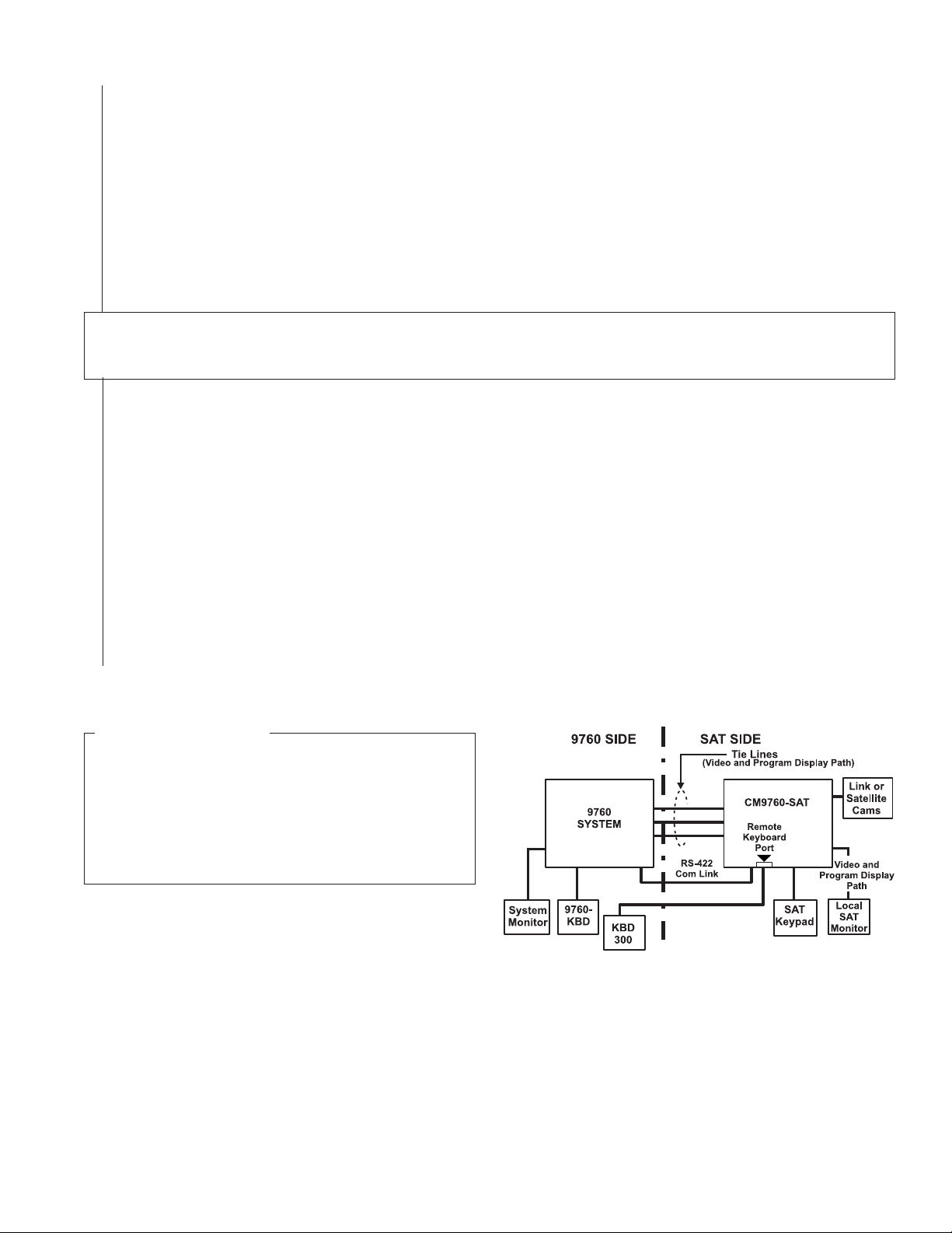
Figure 2-3
Programming Diagram Three
INFORMATION BOX
The coordination issue in this example could be avoided if you ran a
KBD200/KBD300 from the remote keyboard port located on the rear
of 9760-SAT back to the head-end, or 9760 SIDE of the configuration. Then program entry and exit could also be handled by the
9760 operator. In essence, this would amount to doing local SAT
SIDE programming from the 9760 SIDE of the configuration.
Program entry and exit would use the KBD300 and SAT program-
ming would use the 9760KBD. See Figure 2-3.
COMMENTS
With reference to Figure 2-3 and the Information Box above, we
can make the following observation:
To persist in programming the SAT from a 9760 keyboard when a KBD300
is available on the 9760 SIDE is just a convoluted version of Program-
ming Configuration I. Even so, there are some advantages to consider for this configuration:
1. You can program the SAT from the 9760 SIDE without using a preset call function.
2. You can use the KBD300, rather than the 9760 keyboard for SAT programming. The KBD300 is more efficient for programming SAT menus.
3. You can still control local SAT functions from the 9760 SIDE and eliminate the need for a downstream operator.
PROGRAMMING AND CONFIGURATION CM9760-SAT 2-3
PRELIMINARIES
Page 17

SECTION 2 PROGRAMMING AND CONFIGURATION
1.0 SAT MENU PROGRAMMING
Prior to programming the SAT, check to ensure that the bulleted items in the two lists below are either taken care of or that the required
information is readily at hand**. All items in the first list are required.
**The checklist below is based on “
• The SAT-9760 communication interface is in place and correctly wired (see Section 1,
• Identify and make a list of the monitor-out connections on the SAT that are going to be used as tie lines to the CM9760-CC1.
• Make sure you have a monitor attached to the SAT that you can use as your local programming monitor.
• Ensure that a KBD200 or KBD300 (with satellite software) is attached to the local keyboard port on the SAT.
It is important to have the information for the following items before programming the attributes of the item in question. Programming menus for
devices that connect to the SAT can take place before the device is attached, but all devices configured and referenced in the menus should
be connected prior to system operation. Once the system is operational, programming menus for the SAT can be accessed and edited for
currently attached equipment. Care must be taken, however, when making these changes or when attaching additional equipment. If you make
menu choices or device additions that affect the 9760 SIDE of the 9760-SAT interface, remember that you may also have to change existing
configuration files because of these changes. These, in turn, might require interruption of the 9760-SA T communication link and anything else
connected to the 9760 system while new configuration files are loaded.
• Ensure that video inputs to the SAT (link or satellite cameras) are identified as to type (fixed or PTZ). If the receiver is PTZ capable, the
receiver control type should be known (coaxitron or “P” type [RS-422] ).
• Hard-wired alarm and aux configurations.
Programming Configuration I
” located in
Section 2’s
Physical Installation, 1.0 Com Connection
preliminary discussion.
).
LOCAL KEYBOARD INITIALIZATION
Initialization is necessary after power is first applied to the keyboard (SAT SIDE), or if power is cycled on
Figure 2-4
Initialization Screen
the unit or if an operator-induced reset is invoked (see Section 5, Appendix V,
ment)
. When power is applied, the LCD display flashes momentarily, and then goes blank. Initialization
consists of entering the # of the local monitor in the keypad and pressing the MON key. You can do this
immediately after power is applied or you can wait five seconds and then enter the # and press the MON
key. In either case, the result is a 5 second delay before the display of camera input 1 (by default) appears
on the monitor along with other character display information (see Figure 2-4).
The 01 is the camera number. CAM1 is the default camera title. Other information that might appear (time/
date information, for example) does not appear now (the first time through) because of program menu
defaults.
If you have a local monitor attached, but do not yet have any cameras attached, this will not prevent you
from programming the unit. Your programming screens will appear on the local monitor as soon as the
PGM key is pressed, as you will soon see. Programming SAT menus can now proceed.
Default Reset Assign-
2-4 C1510M-A (2/03) SECTION 2
Page 18
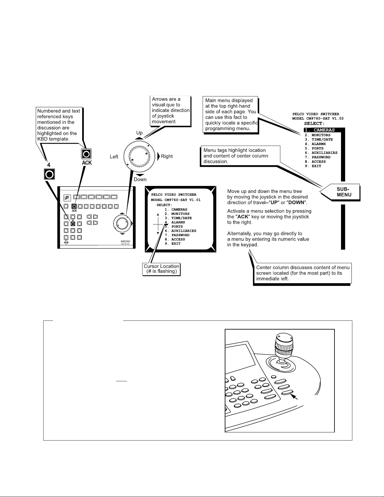
A WORD ABOUT THE MENU DISCUSSION LAYOUT
The menu discussion is split into three columns. At the top, far right side of each page, the SAT main menu is displayed and the sub-menu under
discussion is highlighted. Tagged, drop-down arrows below that, indicate approximately where, within the sub-menu being programmed, that the
referenced sub-menu is discussed. These comments appear in the middle column. The far left column displays a KBD300 template, whose keyboard
movements are highlighted, to indicate the keyboard movements necessary to invoke the program operation(s) being discussed in the adjacent
columns. These conventions are illustrated below.
Figure 2-5
Menu Discussion Conventions
INFORMATION BOX
Programming SAT menus from the CM9760-KBD.
All columns in the menu discussion layout except the far left one, where
keypad movement on a KBD300 is illustrated, are applicable to anyone
programming direct from the 9760 keyboard.
The information contained in the sub-sections entitled
figuration II
PRELIMINARIES,
order to arrive at the SAT main programming menu (see the Camera
Progamming Menu – Page 1 of 2).
The joystick affects cursor movement and some sub-menu selections.
Otherwise, the “Iris” Open/Close button effects item choices. Unlike the
KBD300 keypad, you cannot revert to the main menu using a PGM key
and you cannot choose a numbered selection by pressing a “numbered”
key, nor can you ACK an item: you have no “shortcut” keys. But you can
program the menus. Perhaps not as quickly, but you still can get the job
done.
and
Programming Configuration III
instructs the 9760-KBD user on the steps to follow in
Programming Con-
, located in SECTION 2,
PROGRAMMING AND CONFIGURATION CM9760-SAT 2-5
JOYSTICK
OPEN/CLOSE
IRIS BUTTON
Page 19
2-6 C1510M-A (2/03) SECTION 2
Page 20
PROGRAMMING AND CONFIGURATION CM9760-SAT 2-7
Page 21
2-8 C1510M-A (2/03) SECTION 2
Page 22
The remaining line(s) can be configured as desired,
PROGRAMMING AND CONFIGURATION CM9760-SAT 2-9
Page 23
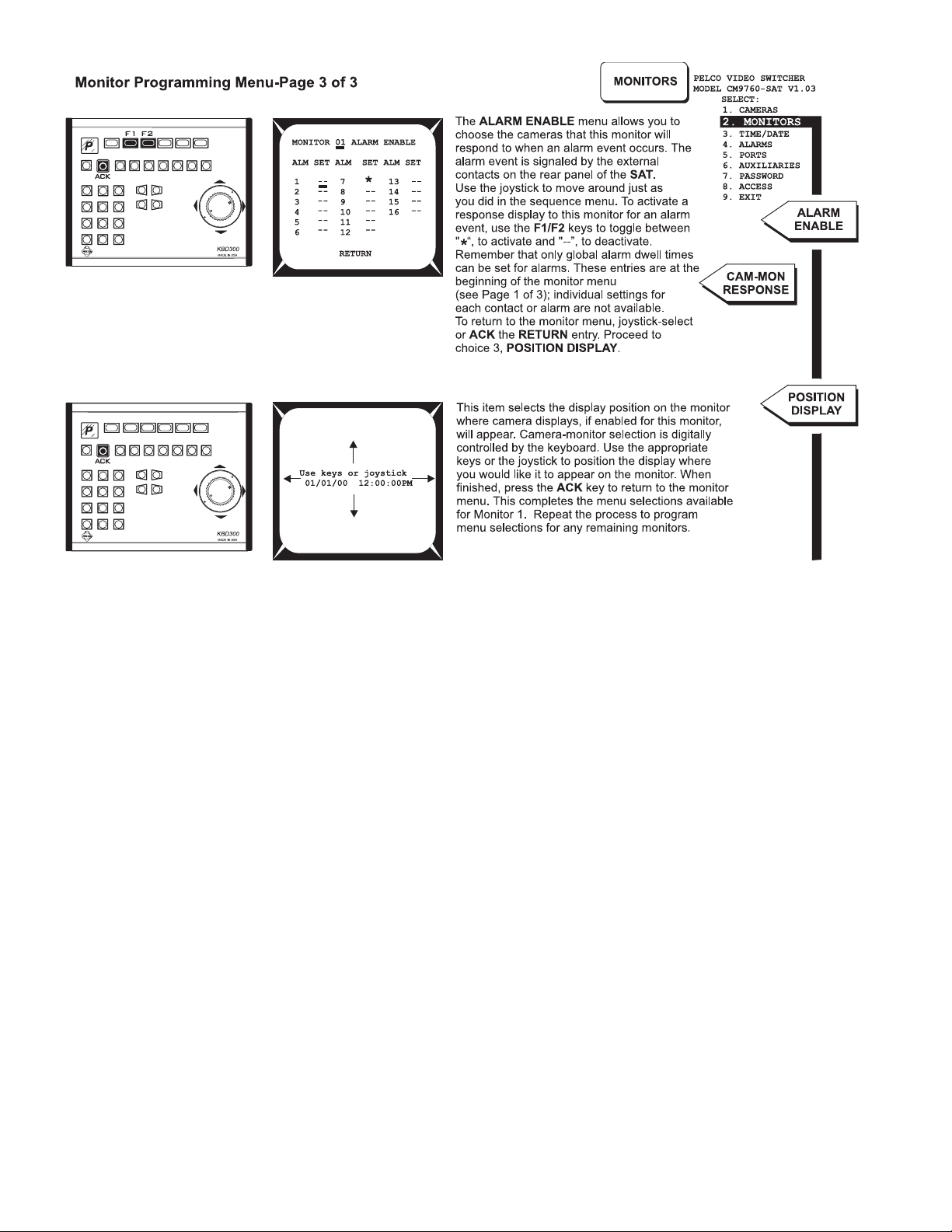
NOTE: The alarm settings in the monitor menu (including
alarm enable) for monitor 04 (LOCAL MODE ONLY) are the
Aux “alarm follow” sources referenced when configuring alarm
activation of AUXs (see Aux Programming Menu Page 1 of 1).
2-10 C1510M-A (2/03) SECTION 2
Page 24

PROGRAMMING AND CONFIGURATION CM9760-SAT 2-11
Page 25

2-12 C1510M-A (2/03) SECTION 2
Page 26

PROGRAMMING AND CONFIGURATION CM9760-SAT 2-13
Page 27

NOTE: The ALM “source” for Aux activated functions
follow the alarm settings for MONITOR 04 made in the
Monitor Programming Menu for that monitor (see Monitor
Programming Menu-Page 1 and 3).
NOTE: Programmed Aux functions are
under local, SAT SIDE control only.
2-14 C1510M-A (2/03) SECTION 2
Page 28

PROGRAMMING AND CONFIGURATION CM9760-SAT 2-15
Page 29

2.0 OTHER SAT PROGRAMMING
NOTE:
Although the following programming operations are performed while in
programming process.
2.1 PROGRAMMING PRESETS
NOTE:
All menus programming should be be completed prior to programming presets, patterns, or zones. In addition, control wiring for
receivers should be completed (see
SECTION 1
,
3.3 Receivers
SAT
operational mode, we include them here as part of the
).
2-16 C1510M-A (2/03) SECTION 2
Page 30

2.2 PROGRAMMING PATTERNS
units
PROGRAMMING AND CONFIGURATION CM9760-SAT 2-17
Page 31

2.3 PROGRAMMING ZONES
2-18 C1510M-A (2/03) SECTION 2
Page 32

3.0 9760 MGR-SAT PROGRAMMING
Before implementing joint 9760-SAT operation, the following configuration files (flat files) must be configured.
1. The COMMS file.
2. The CAMERAS file.
3. The LINK CAMERAS file
and if alarm reporting is invoked
4. The ALARMS file.
The 9760 System Manager program, installed on a PC hard drive connected to the CM9760-CC1 is used to program these files.**
If you received your SAT unit as part of a system shipment, these files may have already been configured to the extent that it was practical or
that information for your system was available. In any case, you can use the information in the sections that follow to:
1. Check existing configuration files against requirements, and
2. To update existing configuration files with the data required to enable 9760-SAT operations.
The following information will be needed to successfully program the flat files associated with SAT operation:
1. You should know the MXB
video inputs.
2. You should know to which physical Sercom port on the controller that the CM9760-SAT is attached.
3. You should know the link camera assignments for the SAT and you should be aware of the receiver types for each connection (PTZ or
fixed).
4. Y ou should also know the communication parameters for the SAT.
physical port destinations of all tie lines that originate as SAT monitor-out lines and terminate as matrix bay
** Additional information about the construction and use of configuration files can be found in the CM9760-MGR manual. Installation and manipulation of configuration files with respect to hardware/software updates and changes is covered in detail in the CC1 controller manual.
3.1 COMMS FILE
Start the System Manager program,
log in (case-sensitive default: Admin),
left-click on the 9760-Setup icon, click
on the Configuration File’s rectangular Setup Files selection bar and
then select the Comms tab from
among the Setup System Configu-
ration tabs.
Setup the Comms file, using the one
illustrated in Figure 2-6 as a guide.
NOTE:
For additional material on the
“nut and bolt” items to be considered
when adding peripheral equipment and/
or software to an existing or new system, consult the appropriate sections
of your controller (CM9760-CC1)
manual.
Figure 2-6
Programming the COMMS file
PROGRAMMING AND CONFIGURATION CM9760-SAT 2-19
Page 33

3.2 CAMERAS FILE
Close the Comms tab and open the
Cameras file by clicking on its tab.
Identify the ports on the MXB to which
monitor-outs from the SAT are at-
tached. Configure the Cameras file
accordingly.
3.3 LINK CAMERAS FILE
Open up the Link Cameras tab next. In
the Link Cameras file, assign unique
logical numbers for the cameras to distinguish them from non-SAT types. Access to link cameras from CM9760KBDs attached to the system node use
the logical numbers just referred to, to
call the satellite camera desired. For
each line entry that that defines a link
camera, enter the PTZ port number to
which the SAT for that camera is at-
tached and also enter the port address
(1-16, on the SAT), to which the Link
Camera is attached. An example Link
Camera file is shown to the right.
Figure 2-7
Programming the Cameras File
Figure 2-8
Programming the Link Cameras File
2-20 C1510M-A (2/03) SECTION 2
Page 34

3.4 ALARMS FILE
In addition to the previous files, it may also be necessary to configure an alarm file if you want to set up the system for head-end alarm
notification. Triggered alarms on the SAT SIDE result in a series of events, controlled, in part, by the programming of the ALARM file on the
9760 SIDE of the configuration. Figure 3-9 is an example ALARM file configured for just one alarm. All 16 SAT alarms can be configured if
you want. Additional configuration files may have to be edited to set up your system to meet other specific operational needs. Suggestions and
additional considerations, as well as alarm operations, are discussed in Section 3,
keyboard operator must be assigned alarm monitors on which to view any activated alarms.
3.2 9760-SA T Alarm Response
. Note Figure 3-18. Each
Figure 2-9
Alarm File
PROGRAMMING AND CONFIGURATION CM9760-SAT 2-21
Page 35

(This page intentionally left blank.)
2-22 C1510M-A (2/03) SECTION 2
Page 36

SECTION 3 OPERATION
1.0 LOCAL SAT OPERATIONS ........................................... 3-1
Selecting Monitors ............................................................ 3-1
Selecting Cameras ........................................................... 3-1
Controlling Cameras ......................................................... 3-1
Operating Sequences ....................................................... 3-3
Controlling Auxiliaries ....................................................... 3-4
IMPORTANT: Initializing keyboards.
For
SAT SIDE
,
local operation, keyboards must be initialized (1) after any
power cycle or (2), after the first time power is applied to a
pendix 5
keyboard or (3), after an operator initiated reset (see
, Default Menu reset Assignments). To initialize a keyboard,
Ap-
enter the number (1-4) of the monitor from which you are going to view
displays, then press the
or after you enter the number and press the
MON
key. You must wait five seconds (before
MON
key) to allow for power
up configuration to take place, after which the number of the selected
monitor appears on the keyboard’s
LED
display.
1.0 LOCAL SAT OPERATIONS
Figure 3-1
Monitor Selection
Figure 3-2
Camera Selection
Figure 3-3
Camera Step-Through
1.1 SELECTING MONITORS
1. Enter the monitor number (1-4) you want
to view.
2 Press the MON button. The monitor num-
ber entered should match that appearing
in the keyboard LED display
1.2 SELECTING CAMERAS
1. Enter the camera number (1-16) you want
to view.
2. Press the CAM button. The camera view
appears on the selected monitor.
1.3 CONTROLLING CAMERAS
1.3.1 Multi-Speed PAN and TILT
Control, KBD200
Use the KBD200’s “T ouch Speed” feature to operate pan and tilts equipped with variablespeed.
Enter a number between 1 (slowest) and 9 (fastest) followed by one of the pan and tilt buttons.
The selected speed remains in the switcher’s
memory until it is changed. Entering zero resets the pan and tilt speed to about 20 degrees
per second.
1.3.2 Variable-Speed PAN and TILT
Control, KBD300/KBD300V
Use the joystick to operate variable-speed pan
and tilt control from the KBD300/KBD300V.
Pan and tilt response increases as the joystick
is deflected from its normal position. Slight deflection causes slow pan and tilt response while
full deflection causes rapid response.
2.0 9760 SAT OPERATIONS ............................................... 3-4
Selecting Link (Satellite) Cameras.…... ............................ 3-4
Controlling Link Cameras…………….. ............................. 3-5
Operating Suggestions………………................................ 3-5
3.0 ALARM OPERATIONS ................................................... 3-6
Local SAT Alarm Response……….... ............................... 3-6
9760 System-SAT Alarm Response…. ............................. 3-7
SAT and SAT-Alarm Unit configurations ........................... 3-9
Up to 16 cameras and four monitors (minus those used as tie-lines) are
available for user access and control via keyboards connected to the SAT.
Access is limited by the following constraints:
1. Physical: a monitor must be available at your location.
2. Software: programmed access (local SAT programming menus)
for monitor/camera use must have been partitioned for access by
the user in question.
1.3.3 Step Through System Camera
Use the PREV (backward) and NEXT (for-
ward) buttons to step through the system cameras, or those cameras partitioned for your keyboard location. The displayed camera order
does
NOT
follow that set up in the CAMERA
SEQUENCE sub-menu of the monitor pro-
gramming menu (see the Monitor Programming Menu-Page 2 of 3). Those settings
effect sequence operations only. Instead, at
each press of the button, the SAT will stop, in
turn, at each video input on the unit. What you
see displayed is influenced by the following
items:
1. If any SAT input lacks a display source,
you will only see a blank screen. For example, if the unit is supplied with input
video on 1 and 16 only and no other inputs, then pressing NEXT or PREV while
between these end-points will result in a
blank screen display. Moreover, you will
have to press the key 14 times to navigate from either end to the other.
2. The situation in (1) can be avoided if the
MON to CAMERA sub-menu, located
in Section 2’s,
Menu
, is configured to bypass those un-
used (or perhaps, unallocated) video inputs. Now, when the NEXT or PREV
button is pressed, you navigate directly
from input 1 to 16, if the NEXT button is
pressed and from input 16 to 1 if the
PREV button is pressed.
Access Programming
NOTE:
There is no indication on the keyboard display that you are actually viewing the
camera you chose. This can be rectified by entering appropriate camera titles for each camera view when programming local
SAT
menus.
OPERATION CM9760-SAT 3-1
Page 37

1.3.4 View a Camera Preset
(for preset programming, see Section 2,
Programming Presets
To manually view any programmed preset
1. Select the camera for which you want to view
a preset by entering the camera number and
pressing the CAM key.
2. Enter the preset number and press the PRE-
SET key.
1.3.5 Operate a Camera Pattern
1. Select a camera with a programmed pattern (see Section 2,
2. Do one of the following:
• If you have just one pattern, press the
PATTERN button to start it.
• If you have two patterns, press either 1
or 2 and then the PATTERN button to
start the desired pattern. (Be careful not
to hold down the PATTERN button or you
will enter programming mode and erase
the existing pattern.)
):
2.1
2.2 Programming Patterns
Figure 3-4
Viewing Presets
).
3. Perform a PTZ function to stop the pattern.
Figure 3-5
Operating a Single Pattern
1.3.6 Change Speeds
1.3.6.1 Focus
Do the following to change the focus speed of cameras with remote control focus:
1. Press a number between 1 (slowest) and 4 (fastest) for the focus speed.
2. Press the FOCUS FAR button. The camera now focuses at the speed you entered until it
is changed.
1.3.6.2 Zoom
Do the following to change the zoom speed of cameras with remote zoom control:
• KBD200–Press a number between 1 (slowest) and 4 (fastest) for the zoom speed, then
press the ZOOM WIDE key.
• KBD300/KBD300V–Press a number between 1 (slowest) and 4 (fastest) for the zoom speed,
then twist the joystick zoom knob counterclockwise (zoom wide). The camera now zooms
at the speed you entered until it is changed.
1.3.6.3 Pan
To change the pan speed of cameras with variable speed hooked to a keyboard without a joystick, enter a number between 1 (slowest) and 9 (fastest) followed by a left or right pan command.
The camera pans at the speed you entered until it is changed.
1.3.7 Turning ZONES ON/OFF
•To turn zones on: press 8, 8, PRESET.
•To turn zones off: press 8, 9, PRESET.
Figure 3-6
Operating Dual or Half Patterns
Figure 3-7
Zoom Operation
Figure 3-8
Turning Zones Off and On
3-2 C1510M-A (2/03) SECTION 3
Page 38

1.4 OPERATING SEQUENCES
Each monitor (video output) has one 16-step sequence that can be
run forward or backward, stopped (by placing the sequence on hold),
or stepped through by pressing either PREV or NEXT while the
sequence is on hold. The sequence status indicator (see Figure 3-9)
displays the current state of a monitor sequence.
1.4.1 Run a Sequence Forward or Backward
Hold down either the NEXT (forward) or the PREV (backward) key
for two seconds to begin running a sequence. The sequence status
indicator under the camera number displays an F (for forward) or B
(for backward) when the sequence begins.
Figure 3-9
Sequence Status and Sequence Display Characteristics
Figure 3-10
Forward and Backward Sequence Operation
1.4.2 Change the Direction of a Sequence
The direction of any currently operating sequence can be reversed. If, in the examples of Figure 3-10, you press the PREV button while the
sequence is running forward, the sequence will run backward. The sequence status indicator will reflect this change by changing from F to B.
Similarly, pressing the NEXT button while the sequence is running backward starts it running forward.
1.4.3 Step Through a Sequence
You can step through a camera sequence in the order the sequence is running (forward or backward) or when a sequence is on hold.
• When the Sequence Status Indicator displays B (sequence is running backward), press the PREV key to step through the sequence.
• When the Sequence Status Indicator displays F (sequence is running forward), press the NEXT key to step through the sequence.
• When the Sequence Status Indicator displays H (sequence is on hold), press the PREV button to step backward through the sequence
or the NEXT button to step forward through the sequence.
Figure 3-11
Sequence Hold
1.4.4 Stop a Sequence
The two ways to stop a sequence are as follows:
• Press the HOLD button. The indicator under the camera
number displays an H (for hold).
• Select a camera.
1.4.5 Turn OFF a Sequence Manually select a camera or press the CAM button.
NOTE:
Programming Menu
QUENCE
Whether or not a camera is available at your monitor viewing location is determined in the access menu (see
). Of those available, which
sub-menu (see
Section 2
,
Monitor Programming Menu-Page 2 of 3
CAM
is used and the order of its appearance is determined by the monitor
).
Section 2
CAMERA SE-
,
Access
OPERATION CM9760-SAT 3-3
Page 39

1.5 CONTROLLING AUXILIARIES
1.5.1 Activating Switcher Auxiliaries, F1-F3
Three function keys (F1-F3) manually control the three auxiliaries that can be connected to the CM9760-SAT. To operate an auxiliary, press an
F1-F3 button. Know how your system is configured and programmed before operating auxiliaries.
• For momentary operation, pressing a key sends a micropulse to the equipment
connected to the auxiliary output.
• For latching operation, pressing a function key is similar to an on/off switch.
• For keyed operation, the auxiliary operates as long as the key is held down.
Even though an auxiliary is programmed to operate when there is an alarm, it can also
be operated manually by pressing the function key.
Figure 3-12
Activating Switcher Aux’s
1.5.2 Activating Receiver Auxiliaries, F4 AND F5
With properly equipped and correctly wired receiver auxiliaries, you
can activate as many auxiliaries as allowed by the receiver from a
KBD200 or KBD300/KBD300V keyboard. The F4 key acts as ON and
F5 as OFF for each receiver auxiliary . If a receiver has multiple auxiliaries, precede the F4 or F5 key with the appropriate auxiliary number
from the number pad.
Figure 3-13
Activating Receiver Aux’s
2.0 9760-SAT OPERATIONS
2.1 SELECTING LINK (SATELLITE) CAMERAS
Link cameras connected to a CM9760-SAT are available for viewing by any 9760 operator for which access to the camera has been partitioned. Link camera identification and availability is realized through the configuration of the Link Camera flat file (see Section 2,
CAMERAS FILE
the associated logical number entered for each listed camera. The logical number is the call-reference used for keyboard command and
control operations by 9760 keyboard operators to call-up satellite (link cameras).
2.1.1 Calling Link Cameras
To call a specific link camera to a 9760 system monitor from a 9760 keyboard, do the following:
a. Be sure the monitor you wish to use to view the display is available and selected.
b. Enter the logical number of the link camera that you wish to call into the keypad of the 9760-KBD and press the CAM button. The referenced
camera display should appear on the monitor.
NOTE:
You can call up all link cameras attached to all SATs within a node from the same operator position, one at a time, if you want. Access to
the camera called must have been granted beforehand (see
2.1.2 Cycling Through Link Cameras
Link camera entries can also be accessed by cycling through the available camera field from the 9760 keyboard by pressing the FWD or BWD
buttons.
). Cameras listed in the Link Cameras file are accessed just as those listed in the Cameras configuration file; namely, by using
Section 2
,
3.3 Link Cameras File
).
3.3 LINK
IMPORTANT:
Any time another link camera is called by the same operator to a different monitor on the
9760 SIDE
of a configuration without releasing control of a previously called camera, the next available tie line is utilized. Conceivably, a single operator could
quickly lock up all available tie lines.
3-4 C1510M-A (2/03) SECTION 3
Page 40

2.1.3 Link Camera Availability
If a called link camera is not immediately available, the following reasons may apply:
a. A tie line may not be available. If all tie lines are in use when you try to access a link camera, the message “No Tie Lines” will appear on
your keyboard LCD display.
b. If the LOCAL/REMOTE option in the ACCESS menu on the SAT SIDE of the configuration is set to LOCAL (see Section 2,
Programming Menu
until 5 seconds after the local SAT user releases control. Of course, the opposite is true if the ACCESS menu entry is set to REMOTE.
), and an SAT operator is using the camera you are trying to call, you will not be able to grab control of that camera
Access
2.2 CONTROLLING LINK CAMERAS
Fixed cameras can be viewed, but not controlled. Of camera-receiver types (RS-422 “P” and Coaxitron) for which control is possible, the physical
geometry of the configuration chosen (based on user choice), is the most important.
• Control from the 9760 SIDE when all monitor-outs are configured as tie lines
1. In this situation, receiver control for SAT video inputs
using RS-422 type controls is possible only if the control wiring is run back to the head-end. Coaxitron control, on the other hand, is exercised through the video
link, which exist as tie lines.
2. Moreover, SAT menu options that affect SAT video
input connections as well as those that affect the 9760SAT interface with respect to control and operation must
still be programmed. Programming is done from the
9760 SIDE of the configuration (see Section Two,
PRELIMINARIES
3. Once programming and control considerations have
been taken care of you can select satellite cameras
(discussed above) and perform almost all other 9760
keyboard related camera operations as described in
the CM9760-KBD manual. These operations include
patterns, zones, presets, and so on, subject to the normal constraints of receiver capability.
).
NOTE:
Total, head-end,
control operations.
section (see
9760 SIDE
Section 3
users, is an issue only to the extent that it lessens or
increases the useful integration of the
9760-SIDE
SAT
control is discussed in detail in the previous
,
1.0 LOCAL SA T OPERATIONS).
control, eliminates
SAT’s
alarm reporting capabili-
SAT SIDE
Control, for
ties with those that already exist in the 9760 system itself.
IMPORTANT:
The following control problem might occur
when an operator is controlling a satellite CAM under PTZ
control on a local system (9760) monitor. Care must be taken
before issuing a command that overrides and replaces a currently
controlled
COPY (
SAT
camera with a
COM, COC, CCO
NON-SAT
camera via a MACRO type
step commands) command. The CM9760SAT may not issue a stop command to the previously controlled PTZ
camera, as it does not know that the switch took place. The result is
that the PTZ camera will continue to move. A possible work around
might involve using the
of COPY type commands for monitors displaying
information about the ?SW step command, see the
mands and Setup Details”
?SW
step command to avoid inadvertent use
SAT
cameras. For
“Macro Step Com-
section in the 9760-MGR manual.
• Control from the 9760 SIDE when concurrent control
exists on the SAT SIDE and a mixture of local and tie line-
configured monitor-outs exists.
Control operations viewed from the 9760 SIDE under concurrent control differs little from single-side control as discussed above. However,
there are two obvious differences:
1. Fewer available tie lines limit the maximum number of SAT cameras available for operator use on the 9760 SIDE at any one time.
2. Competition with SAT operators for camera control and an increased chance of inadvertent anomalies.
2.3 OPERATING SUGGESTIONS
You may have no choice in the use of single-side versus concurrent control of SAT functions because of on-site considerations other than
those discussed here. Yet, based on the foregoing discussions, as well as other considerations, the following suggestions and comments are
offered when using either of the two control options we have outlined:
1. If local SAT operation and control is enabled or desired, then we suggest that you use the 9760 SIDE primarily for alarm reporting
functions and minimize 9760 SIDE generation of control operations directed at SAT cameras. Let SAT SIDE operators have primary
control of SAT cameras.
2. If no local SAT SIDE operations are entertained and all monitor-outs are configured as tie lines, then SAT programming and all control
and alarm reporting functions are controlled by 9760 SIDE operators.
OPERATION CM9760-SAT 3-5
Page 41

3.0 ALARM OPERATIONS
3.1 LOCAL SAT ALARM RESPONSE
Whenever an input alarm condition occurs on the SAT, the local SAT opera-
tor (if previously programmed for alarm access notification) will see a display
similar to the following on the local monitor screen:
The A is the sequence status indicator’s shorthand for a current alarm condition.
The alarm notification occurs because:
1. The Alarm menu input condition (N.O., N.C.) has been met and the alarm
is armed for local SAT response, and
Figure 3-14
Activated Alarm
2. The local SAT user’s monitor has been programmed (in the Monitor Pro-
gramming menu) to see alarms, in general, and to see the armed camera
in question, in particular.
User response to the alarm condition is also based on Monitor menu
entries for the monitor.
ACKNOWLEDGMENT
• If an alarm is programmed for automatic acknowledgment,
NO
Figure 3-15
Alarm Acknowledgment Response Settings
the alarm will remain on the screen for 10 seconds or as
long as the alarm contact is held plus 10 seconds.
AUTOMATIC
NOTE:
Alarms will interrupt sequence opera-
tions in progress on local
SAT
monitors. Once
the alarm is acknowledged, the sequence will
return to where it left off
• If an alarm requires manual acknowledgment, the alarm
will remain on the screen until it is acknowledged. Multiple
alarms sequence according to the alarm dwell setting in the
Monitor menu.
MANUAL
For alarms requiring manual acknowledgment (this also applies to automatic alarms before their programmed timeout), releasing or acknowledging the alarm can be accomplished in one of two ways:
• By pressing the ACK key while the alarm is currently displayed.
• By entering the number of the alarm before pressing the ACK key regardless of whether the alarm is displayed.
NOTE:
sponse on both the
SIDE
If a programmed alarm elicits a re-
9760 SIDE
and the
SAT
of a configuration, clearing or acknowledgment of the alarm on either side of the configuration has no effect on the other side of the
Figure 3-16
SAT Alarm Clearing
configuration. Alarm acknowledgment influences are mutually exclusive.
3-6 C1510M-A (2/03) SECTION 3
Page 42

3.2 9760 SYSTEM-SAT ALARM RESPONSE
The response to an alarm that is programmed and armed at the local, SAT level,
can also be configured for a corresponding
9760 SIDE alarm notification and response.
For this to occur, the System Alarm column
for the alarm in question must be edited. This
occurs in the local SAT Alarm menu.
A System Alarm column entry completes
SAT SIDE programming menu requirements for a CM9760-KBD keyboard user to
be notified of the corresponding local alarm
if proper programming for alarm response
functions have been configured on the 9760
SIDE of the system.
NOTE:
Local and System alarm notifications are mutually exclusive: both, or one, or neither can occur based
on programming.
Consider, for a moment, that the SAT alarm
sub-menu for alarm contacts 1-8 is configured as shown in Figure 3-17.
As shown, Alarm #1 activation is not only set for SAT SIDE
alarm notification but will also send a System Alarm notification number of 0001 to the CM9760-CC1 when the local
SAT alarm occurs.
The alarm functions in the following configuration files
(housed in the 9760-CC1 but programmed using the 9760MGR program) must be configured before the 9760 keyboard user can be notified of and view the alarm:
In the Comms file:
1. Each keyboard must be assigned Alarm monitors if a
visual display of the alarm camera (in addition to keyboard notification) is desired. For example, note that in
Figure 3-18, keyboard number 2 is assigned alarm
monitors 1 through 5.
Figure 3-17
Alarm Contact Menu
Figure 3-18
Assigning Alarm Monitors
In the Alarms file:
2. The number entered in the System Alarms column of
the ALARMS menu on the SAT SIDE corresponds to
the number found in the Physical Number column of
the ALARM configuration file on the 9760 SIDE.
The number in the associated Logical Number column
of the ALARM file is used to ARM the alarm from the
9760 keyboard. The camera to be called in response
to Alarm 1 being activated is entered into the Alarm
Camera Switch sub-menu of the ALARM file.
NOTE:
To enable
9760-SIDE, automatic
acknowlegment
of alarms, fill in the Auto Reset (see Figure 3-19) column for
the associated alarm with a time (in seconds) that you want
the alarm to remain active before it is reset.
Figure 3-19
Configuring 9760 SIDE Alarm Response Numbers
OPERATION CM9760-SAT 3-7
Page 43

In the 9760 keyboard:
3. Finally, the programmed logical number (100) associated with the System Alarm
number (in our example, 1) is used to ARM the alarm on the 9760 SIDE. This is
done from the 9760 keyboard via its program menus or, if desired, it can be
accomplished through automatic configuration via macro execution when the
keyboard user logs onto the system.
To accomplish this task direct from the 9760 keyboard, perform the following
steps:
a. After logging onto the system from the keyboard, press the key to
proceed to the DEFAULT MENU (see Figure 3-20).
b. Enter the logical number of the alarm you want to ARM in the keypad and
press the blue button below the ALARM icon as indicated in Figure 3-20.
c. The ALARM SUB-MENU appears. Activate the indicated icon in Figure 3-
21 to ARM the alarm. If you have not previously entered a PIN number for
the DEF menu, the display in Figure 3-22 appears. Enter the default PIN of
1234. The display will revert back to Figure 3-21. Press the blue button to
activate the ARM function. The ARM DIS’ icon turns opaque as in Figure 3-
23. This completes ARMing the alarm for Physical Alarm 1.
Additional alarms may be armed from this menu by entering the associated logical
number in the keypad and pressing the ALARM (bell) icon. This takes you back to
Figure 3-21, which now displays the new number in the menu; the ARM DIS’ icon is
clear and can now be activated to ARM the next alarm. The result is again Figure 323, except that now, the new numbers for the ARMed alarm appear.
Figure 3-20
Default Menu
▼
Figure 3-21
Alarm Sub-Menu
▼
Once the above equipment menus are configured and an alarm is received from the
CM9760-SAT, the alarm display in Figure 3-24 is activated and appears on the LCD
display of the 9760 keyboard (if you happen to be in the ALARM menu). If not, the
alarm bell icon still appears no matter what menu you are in. The bell icon flashes,
going from clear to opaque and back again. The logical number associated with the
alarm appears on the display and the alarm camera number called in response to the
alarm, also appears.
If, as referenced in step 2’s “NOTE” (automatic acknowledgment is not enabled), then
you can navigate to the Alarm menu shown in Figure 3-24, and can then reset the
alarm shown, pause the alarm or reset all alarms (if there are multiple alarms).
Resetting the alarm does not disarm the alarm. That must be done separately , if that’s
what you want. Otherwise, resetting the alarm allows the system to be ready for the
next activation of this alarm, which will not occur until the source of this alarm activation is corrected first.
More extensive alarm programming functions associated with the system are possible but are not discussed here. Consult the appropriate sections of the 9760-MGR
and 9760-KBD manuals.
Figure 3-22
DEF PIN Menu
Figure 3-23
Armed Alarm
▼
Figure 3-24
Operator Alarm Notification
3-8 C1510M-A (2/03) SECTION 3
Page 44

3.3 SAT AND SAT-ALARM UNIT CONFIGURATIONS
Two SAT Units on the Same NODE
One SAT unit can generate 16 possible alarms. Each alarm results in a 9760 system alarm if the SAT alarm is assigned a System Alarm
number in the SAT ALARMS file (see Section 2,
Moreover, each System Alarm number (on the SAT SIDE) corresponds to the same number in the Physical Number column of the ALARM
configuration file (on the 9760 SIDE).
If two SAT units are connected to the 9760 system, 32 possible alarms notifications can be generated by the SAT SIDE and passed on to the
9760 system. Theoretically , it doesn’t matter which numbers (of those available) you pick to use as System Alarm numbers as long as you do
not repeat any number among the total used by all SAT units and ALARM units combined. We shall discuss 9760-ALM units mixed with SATs
shortly, but first consider two SAT units on the same node.
The portions of the SAT Alarms menu and the 9760 ALARM configuration file that relate to our discussion are shown below in Figure 3-25.
Even here, you can see that there are different ways of configuring the menus involved. Usually , the simplest is the best. Here, the simplest is
to associate the first 16 (1-16) System Alarm numbers with SAT 1 and the second 16 numbers (17 to 32) with SAT 2. The associated Physical
Number column’s range in the 9760 ALARM configuration file runs from 1 to 32 (1-16 for SAT 1 and 17-32 for SAT 2).
Alarm Programming Menu-Page 1 of 1
).
(The Simplest) (A Variation)
Figure 3-25
SAT Alarm Configuration – Two SATs
For each 9760 Physical Number (1-32) in the configuration file, an associated Logical number is assigned. The Logical number is used to ARM
the alarm from the 9760 keyboard. Each Physical Number (or defined alarm) is also associated with a Logical camera number in the Alarm
Camera Switcher sub-window of the 9760 Alarm configuration file (see Section 3,
referenced there will be called by the 9760 when the associated alarm is triggered. The logical camera numbers, which in this case are SAT
satellite cameras, are port specific with respect to the SAT unit that they belong to. That relationship, in turn, is determined by the configuration
of the Link Cameras configuration file (see Section 2,
Once configured, alarm response for each alarm occurring on any unit is the same as that already described in the previous section.
3.3 Link Cameras File
3.2 9760 System-SAT Alarm Response
).
). The camera
OPERATION CM9760-SAT 3-9
Page 45

SATs and ALARM Units on the Same Node
Alarm units and SAT units both utilize the same 9760 Alarm Con-
figuration File. The following statements compare and contrast
similarities and differences between the two units:
One Alarm unit can handle 64 alarm inputs per unit.
One SAT unit can handle 16 alarm inputs per unit.
Alarm units (up to four) may be daisy-chained on a single port.
SAT units cannot be daisy-chained.
Alarm units can interface 256 alarms per port.
SAT units can interface 16 alarms per port.
Up to 10 ports may utilize Alarm units, for a total of 10 X 256 or
2560 hard-wired alarms/system.
SAT units may attach to as many ports as are available, however, the combined ALARM-SAT mix cannot exceed 2560 hardwired alarms.
Alarm units utilize alarm base addressing.*
SAT units do not.
Alarm units are added to the system on a 4 per port basis.
SAT units are added on a 1 per port basis.
The important thing to consider between ALARM and SAT units
is what they share or have in common, which is the ALARM file.
Several ALARM file configurations, based on various equipment
configurations, are illustrated in Figure 3-26.
* INFORMATION BOX – Alarm Base Addressing
■ Fact 1: Alarm base addressing is used with alarm units only.
■ Fact 2: The number entered in the Alarm Base Number box
(for alarm units) corresponds to a number in the physical alarm
input column of the Alarm configuration file (See Figure 2-9,
File.
Ignore its mentioned use there for SAT SIDE menu pro-
gramming).
Definition: The Alarm Base Number defines the starting point
from which alarm “counting” begins for alarm base addressing as
applied to alarm units. Alarm units utilize alarm base addressing
in “bite-size” increments (per port) of 256, spanning a range whose
count starts at the value entered into the Alarm Base Number box.
Working Rules:
■ Rule 1: The Alarm Base Number for the first alarm unit attached
to a CC1 port is set to 1. Subsequent alarm units (up to four) are
daisy-chained off the first unit on the same port.
■ Rule 2: If you add another alarm unit (say, number five), you
must attach it to a different port. You must also enter a new number to count from in the Alarm Base Number box for the port to
which this alarm unit is attached. In this case, that number would
be 257. Subsequent alarm units (up to four, total, for this port)
would utilize alarm addresses 257-512 (accommodating 8 Alarm
units on 2 ports).
■ Rule 3: The combined total of hardwired SAT -Alarm unit inputs
or addresses cannot exceed 2560 per system. The number (2560)
was originally derived from the use of four alarm units per port
(256 total) within a 10 port limit (256 x 10). At present the number
of hardwired inputs allowed is still 2560.
■ Rule 4: It is best to define alarms for Alarm units before those
for SATs, as is done in the first two configuration examples below.
Alarm
One SAT unit and one ALARM unit on the
same node:
Figure 3-26
Various SAT-ALARM Configurations
As stated earlier, SAT alarm definitions do not use nor depend upon alarm base addressing. So the following question might arise: If you had
one ALARM unit that used only the first 48 inputs of the Alarm file, could you take unused inputs 49 through 64 and use them as SAT alarm
inputs?
The short answer: Yes, you can use any alarm input for the
SAT as long as it is not actually configured for use by any other
piece of equipment.
The long answer: If you are not pressed for port space, it is
not a good thing to do. The obvious problem is that (1) you create
an alarm assignment overlap from the 9760-ALM’s point of view.
To the 9760 ALARM configuration file, an alarm is an alarm. It
doesn’t really care where it originates. For the 9760-ALM unit,
One SAT unit and two ALARM units on the
same node:
however, that is a different story . That leads to problem (2), which
is that there now is one more item of information to track. If more
alarm units are daisy-chained to the original port, will anyone remember the SAT unit? If the front panel switches of the single
alarm unit are changed to take advantage of those last 16 unused inputs, is anyone going to remember that the SAT unit is
using those numbers? If possible, do not use alarm-input
numbers already allocated to ALARM unit use,
whether they are used or not.
Two SAT units and one ALARM unit on the
same node:
3-10 C1510M-A (2/03) SECTION 3
Page 46

SECTION 4 SYSTEM AND MULTIPLIEXER EXAMPLE
1.0 SYSTEM EXAMPLE ........................................................ 4-1
1.1 OPERATION OF THE SYSTEM EXAMPLE ............... 4-9
2.0 MULTIPLEXER EXAMPLES .........................................4-11
1.0 SYSTEM EXAMPLE
We shall use Figure 4-1 to highlight the processes involved in integrating a CM9760-SAT into a 9760 environment.
Figure 4-1
System Example
OVERVIEW
Integrating an SAT into a 9760 system occurs in two stages:
(1) hooking it up (items 1-6 below), and (2) programming it (items
7 and 8). The list below is based on the diagram above. It is as
follows:
1. Attach a keyboard to the local SAT keyboard port.
2. Attach a local monitor to the monitor-out port on the SAT.
3. Establish a communication link between the CM9760-CC1
and the CM9760-SAT.
4. Run link-cameras (satellites) to the video input BNCs on the
rear of the SAT.
5. Run tie lines from the appropriate monitor-out BNCs on the
SAT to available video input BNCs on the rear of the
CM9760-MXB (matrix bay).
6. Attach and configure alarm inputs and wiring.
** For link-camera inputs 1, 3, 5, and 7 (SAT SIDE), we assign (for 9760
purposes) corresponding logical numbers of 5001, 5003, 5005 and 5007.
We limit our discussion to these specific inputs as we discuss the system
illustrated above.
7. Program the local SAT menus to correspond to your physi-
cal hook-up.
8. Program the 9760 System to incorporate the SAT unit into
the system environment.
We shall not engage in detailed discussions of non-SAT related
matters. We will discuss, in turn, each of the above numbered
items. For each, we shall (1) isolate that portion of Figure 4-1
under discussion (2) discuss any and all applicable programming
menus associated with that item, and (3) add other pertinent remarks and/or give appropriate manual references where applicable. Please note that items 7 and 8 (software) are not discussed
as individual items, separate from other items in the installation
process, but are considered at the time each physical item (1 through
6) is discussed. In actual practice, programming is not necessar-
ily performed concurrent with physical setup. We do so here because our purpose is to inform, to illustrate the close relationship
between the device and the program that controls it and, in the
process, perhaps point out how best this manual can be put to
use.
BASIC SYSTEM EXAMPLE CM9760-SA T 4-1
Page 47

Before we begin, note that link-camera video input # 5 in Figure 4-1 is shown
as a loop-through input. This requires SAT top-cover removal. This is done
first if the SAT unit is to be rack-mounted. To configure this input for loopthrough operation, move the JP5 jumper from 75-ohm term (factory default) to
looping (refer to Section 1, 3.2.1 Looping Video Inputs). Now we can begin.
1. Attach a keyboard to the local SAT keyboard port.
NOTE: RJ-45 cable run between the keyboard
and the 9760-SAT local keyboard port (shown in
the illustration) is normally supplied. be sure to
check that the cable supplied (“straight”) is
correct before installing (see Section 1, 3.6
Local Keypad and Appendix I, Communication
and the Connection Tutorial, if necessary).
NOTE:
Figure numbers are not allocated for the remainder
of this section, as the features under discussion are subsets of the system example, which does have a number.
2. Attach a local monitor to the monitor-out port on the SAT. **
4-2 C1510M-A (2/03) SECTION 4
Page 48

3. Establish a communication link between the CM9760-CC1 and the CM9760-SAT.
BASIC SYSTEM EXAMPLE CM9760-SA T 4-3
Page 49
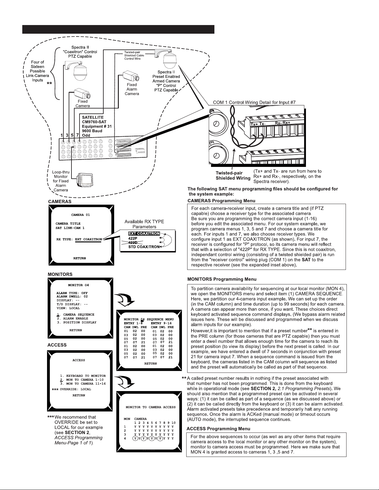
4. Run link-cameras (satellites) to the video input BNCs on the rear of the SAT.
The SAT menu programming files referenced below must be edited
for our system example to work.
NOTE: COM 1 port
protocol must be
set for the receiver
in quesiton using
the PORTS menu.
4-4 C1510M-A (2/03) SECTION 4
Page 50

The link-camera configuration file on the 9760 SIDE, mirrors the choices for the link-camera inputs selected in the camera menu on the SAT SIDE.
The input numbers associated with the 16 inputs on the SAT correspond to the fixed numbers located in the Phy Num column of the Link Cameras
file. The items to consider in the Link camera file for our system example are pointed out below:
BASIC SYSTEM EXAMPLE CM9760-SA T 4-5
Page 51
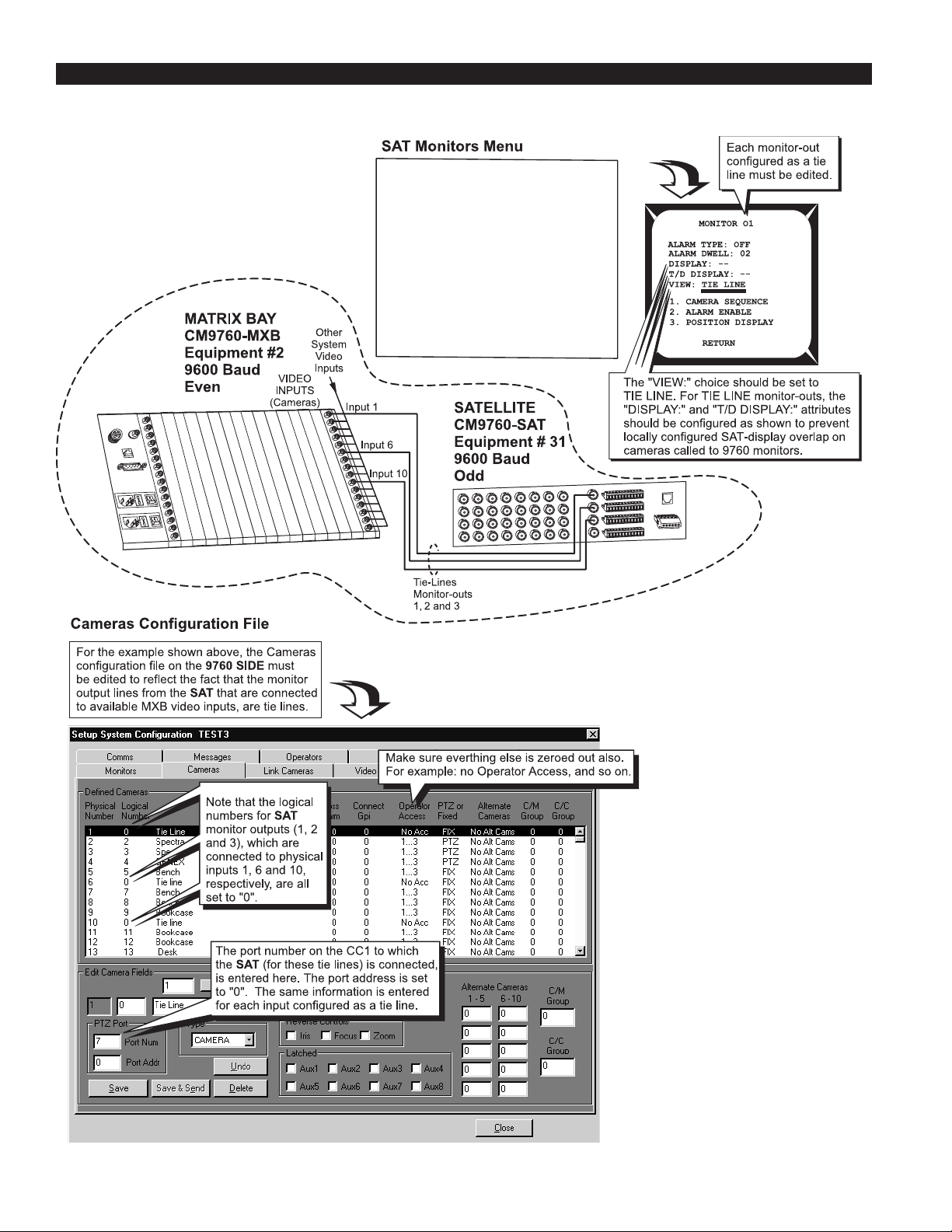
5. Run tie lines from the chosen monitor-out BNCs on the SAT to available input video BNCs on the rear of the CM9760-MXB (matrix bay).
Note the physical inputs (the actual physical port number) to which these tie lines
are run and then configure the appropriate files and menus (as shown below).
Monitor output use (local or tie line) is set
up for each monitor output line in the SAT
Monitor programming menu. In this portion
of our system example, we are concerned
only with those outputs configured as tie
lines. Video inputs to the SAT are place
upon these tie line in requested to (1)
operator initiated requests from a System
9760 keyboard users or (2) as the result of
alarm activated requests to place the
associated camera display on a tie line
(see Section 3, 3.2 9760-SAT Alarm
Response).
4-6 C1510M-A (2/03) SECTION 4
Page 52

6. Attach and configure alarm inputs and wiring.
In our system example, we show a door that triggers an alarm if it is opened.
A number of conditions must be met to enable alarm activation and response. These are illustrated below.
BASIC SYSTEM EXAMPLE CM9760-SA T 4-7
Page 53

Item 6 (continued)
4-8 C1510M-A (2/03) SECTION 4
Page 54

1.1 OPERATION OF THE SYSTEM EXAMPLE
That concludes the hook-up and programming of our system example. Once the system to which the SAT is attached is operational, the
following items remain to be configured (in operational mode) before alarm operation is totally enabled:
1. On the SAT SIDE, we must still define preset 21. If an alarm triggered before we created the preset, the designated camera input display
( #7) would appear on the local monitor, but the display might be something other than the preset position view that we want.
2. On the 9760 SIDE, we must ARM all defined alarms that we want to see from our keyboard position. ARMing is done from the 9760
keyboard position. In the real world, this would more than likely be taken care of with a Macro that executed whenever the operator logged
onto the system. If an alarm occurred on the SAT SIDE before the alarm was ARMed on the 9760 SIDE, the 9760 SIDE would have
no idea that an alarm occurred.
To accomplish (1), follow the instructions in Section 2,
for the system example. A preset label can also be created, if you want.
To accomplish (2), the 9760 keyboard is used to ARM the alarm. The logical number (100) for defined alarm (0001) is used to ARM the alarm.
Follow the instructions in Section 3,
NOTE:
Alarm response by operators on the
3.2 9760-SAT Alarm Response
9760 SIDE
2.1 Programming Presets
on how to ARM an alarm from the 9760 keyboard.
and the
SAT SIDE
and program preset 21 for the alarm-input camera (input 7)
are independent of each other, once an alarm condition is
sensed. That is, clearing a triggered alarm on one side of the configuration has no effect on the other side.
The following is a relatively straightforward time-line of the events that unfold when the alarm-wired door is opened on the SAT SIDE of the
configuration, triggering an alarm event.
1. The door opens, causing the N.C. contacts to open, which signals an alarm condition on the SAT SIDE of the configuration.
2. The alarm overrides any local operator actions in progress and, because of the SAT Alarms file settings, the local monitor display (MON
4) switches to the display input from video input # 7. That display appears on the local monitor. The status sequence indicator on the local
monitor shows an “A” to indicate the alarm condition.
3. In conjunction with (2), the camera for this video input is already at or is in the process of traveling toward alarm preset position 21.
4. The system alarm notification number (0001), entered in the local Alarm menu is sent to the 9760 SIDE of the configuration. Even if the
local SAT operator were to ACK and clear the alarm at this time, it would not affect alarm notification to the system. Once an alarm
occurs, that alarm information is immediately passed on to the 9760 SIDE of the configuration and nothing the local SAT operator can
do will prevent system notification if the menus are so configured.
5. In response to alarm notification from the SAT unit, the system (per instructions in the Alarm configuration file) asks the SAT to place the
video from logical link camera 5007 on the first available tie line.
6. The SAT’s response is to place video input 7 (logical 5007) on an available tie-line.
7. On the 9760 SIDE, the received video is placed on an available alarm monitor (previously assigned) for the operator on that keyboard
position via the Comms file. The alarm display parameters are governed by the alarm mode chosen In the System configuration file.
8. On the 9760 SIDE, the System Window (in the 9760-MGR, or System Manager program) indicates the triggering of the alarm on the
SAT SIDE by displaying a line similar to the following:
09:05:38 16/08/00 Nd:01 ALARM 0001 TRIGGER SAT Alarm Op:01 Pr:09
BASIC SYSTEM EXAMPLE CM9760-SA T 4-9
Page 55

Shortly thereafter (during the time that steps 4 through 7 occur, which are almost concurrent from a user viewpoint ) the System manager’s
System window will indicate that the video from logical camera 5007 has switched to an alarm monitor. It might look something like this:
9:05:38 16/08/00 Nd:01 SWITCAMMON Camera: 5007 Monitor: 001 Op: 1
9. At the same time, the AT diagnostic screen’s Monitor box shows that camera display 5007, which utilizes a tie line, is displayed on Mon 1.
The system box (or system error line) is illustrated in Figure 4-2.
Figure 4-2
Sample System Diagnostic Screen
10. The keyboard on the CM9760-KBD for the operator viewing this alarm will show the following:
Figure 4-3
System Example 9760 LCD Alarm Event
If more than one alarm happened (with none being reset) the alarm numbers on the 9760KBD LCD screen sequence and cycle among all
alarms triggered. As each alarm number appears on the LCD screen, the corresponding logical number of the associated alarm camera
appears next to the camera icon.
This concludes the system example, which gives you a hint of the processes involved in integrating an SAT into a 9760 System configuration
and highlights how information affecting such a setup can be located in this manual.
4-10 C1510M-A (2/03) SECTION 4
Page 56

2.0 MULTIPLEXER EXAMPLES
EXAMPLE OVERVIEW
Example One: Software version 7.80.003 and greater supports control of PTZ capable cameras through the Genex multiplexer . The first
example briefly addresses this in relationship to a 9760-SAT system environment. Programmed, Genex related, 9760 configuration files are
used in Example 1, but are discussed and illustrated in Example Two, Part I.
Example Two: The second example discusses, in greater detail than is used in Example 1, the connections and programming requirements
necessary for the operation of
environment. These functions are keyboard activated, using icon-labeled references to call up multiple screen displays generated by the
Genex. The SAT operator uses the KBD200,300,or 300Vs. The 9760 operator uses the 9760-KBD.
EXAMPLE ONE: CAMERA CONTROL THROUGH THE GENEX IN A 9760-SAT SYSTEM ENVIRONMENT
Consider the illustration in Figure 4-4
Figure 4-4.
Camera Control Through the Genex
multiplexer functions from either the 9760 SIDE and/or the SAT SIDE within a 9760-SAT system
In the above Figure, note the following:
1. Camera inputs to the Genex are looped and serve as corresponding inputs to the CM9760-SAT.
2. A video path is available to any operator on either side of the configuration to all Genex attached cameras, including Spectra input 1. For
the SAT operator, access exists through the looped input from the Genex; for the 9760 operation, it exists through the same path via the
tie line connections between the SAT and the MXB.
3. You must also (as a minimum), configure the Genex for the following (consult the Genex manual for further details):
a. Set video termination. This can be done globally in the System Setup menu (hold the VIEW button down for two seconds) or it can be
done on a per-camera basis in the Camera menu (hold the associated CAM button down for two seconds). In our example, the inputs
for all cameras to the Genex should be set for LOOP HI-Z.
b. Camera protocol should be set to Coaxitron format via the Camera menu.
c. The Unit ID should be set to 1 and the COMM TYPE setting (both accessed through the Advanced Menu selection) should be set to
MASTER (KBD-T/D).
BASIC SYSTEM EXAMPLE CM9760-SA T 4-11
Page 57

Figure 4-4 illustrates the minimum physical connections using the pieces of equipment required for camera control through the Genex. Specifically illustrated are the coaxitron, camera-related connections necessary for operators on both sides of the configuration to have controlaccess to Genex camera input 1. The SA T SIDE operator has access by entering 1 on his keypad and pressing the CAM button; the 9760 SIDE
operator has equal access and control by calling camera 5001 to his available monitor . Other than Genex-looped inputs, the SAT operator can
also control direct “SAT-connected” cameras that use Pelco “P” type protocol (not run through the Genex, but connected directly to other SAT
video inputs; control wiring must also be run). At the same time, operators on the 9760 SIDE can view and control all SAT connected cameras
that are properly configured.
EXAMPLE TWO: MUX CONTROL IN A 9760-SAT SYSTEM ENVIRONMENT
Part I - Mux Control from the 9760 SIDE
Note that the Genex control line in Figure 4-4 connected to the COM “IN” port is connected to Sercom input port 10 on the CC1. That’s one
requirement for enabling MUX control from the 9760 SIDE.
To fully enable MUX control, Figure 4-4 needs to be altered slightly. That change is reflected in Figure 4-5. It involves the connection of a video
cable between the MUX main output on the Genex and an available BNC video input on the CM9760-MXB. We choose BNC input 1 1.
Figure 4-5.
9760-SIDE Mux Control
4-12 C1510M-A (2/03) SECTION 4
Page 58

Associated with this and the previous example are two 9760 SIDE configuration files that affect Genex integration into the system. The first
(Comms file) is applicable to both examples. The second (the Camera file) is applicable to both except that the Genex configured camera field
for “10” is not applicable to example one. Both of these files have to be configured for both examples. The COMMS configuration file is illustrated
in Figure 4-6.
In this file (Comms), the Genex
parameters are entered in the
Edit Port Fields for the port that
it is connected to, (port 10).
Figure 4-6.
Comms File and the Genex
The next configuration file is just as important. This is the Camera file. Here the Genex input for the Mux Main input to the MXB is configured as
a multipexer input in the Type field. When this input is called by the 9760 SIDE operator (input 11, logical), the multiplexer control icons appear
on the 9760 keyboard LCD screen. From there, the operator can change the number of cameras displayed on the assigned monitor simply by
pressing the control icon desired.
Figure 4-7.
Camera File and the Genex
BASIC SYSTEM EXAMPLE CM9760-SA T 4-13
Page 59

Part II - Mux Control from the SAT SIDE
Mux control from the SAT side is enabled by reconfiguring the example system we have been using to that shown in Figure 4-8.
Figure 4-8.
SAT SIDE Mux Control
Note the following changes and comments:
1. Mux Main no longer is attached to the MXB on the 9760 SIDE. There are now 8 video inputs to the SAT instead of 7. Mux Main is now
the 8th input to the SAT.
2. The data “IN” port on the Genex is wired to the remote keyboard port on the SAT; it is no longer connected to the 9760.
3. Operators on the 9760 can view Mux-activated screens on the SAT SIDE (if the additional SAT input [8] is added to the Link Camera file
on the 9760 SIDE). In our example, it would be 5008. If the operator entered 5008 into his keypad and pressed the CAM button the
multiplexed input from the SAT SIDE will appear on his assigned monitor.
4. Any SAT keyboard operator can initiate multiplexer functions by pressing the SHIFT key (the LED lights) and choosing the function
display desired. Once initialized, any other operator on the system can effect changes to the multiplexed display. Any changes will be
reflected in all local monitors at the same time.
5. If a 9760 operator has called up the SAT Mux input (5008), any display activity on the SAT SIDE will be reflected on the operator’s
assigned monitor on the 9760 SIDE of the configuration.
4-14 C1510M-A (2/03) SECTION 4
Page 60

SECTION 5 APPENDICES
APPENDIX I COMMUNICATION AND CONNECTION TUTORIAL ................................................................................................5-1
APPENDIX II REMOTE KEYPAD CONNECTION............................................................................................................................5-2
APPENDIX III KEYPAD DEFINITIONS AND TEMPLATES............................................................................................................... 5-5
APPENDIX IV MODELS AND ASSOCIATED EQUIPMENT..............................................................................................................5-7
APPENDIX V DEFAULT RESET ASSIGNMENT ..............................................................................................................................5-7
APPENDIX VI CONNECTOR PINOUT LISTINGS FOR ALL CONNECTORS ..................................................................................5-9
APPENDIX I – COMMUNICATION AND CONNECTION TUTORIAL
There is only one, really basic set of rules that you must consider
when wiring two 9760 communication devices together.
Those rules are given in item 3 below.
Frustration arises only if the information you are given does not
enable you to identify those elements of the connection you need
to know or if the information you need is not readily at hand.
You should not be satisfied to just plug in a cable “type” because
you are told to without having the slightest idea what to do if it
doesn’t work. It’s easy enough to check the parameters for yourself so that when you do plug that cable in, you expect it to work.
In fact, you should be surprised if it doesn’t work.
You will never get in trouble when wiring two 9760 communication devices together, if you know and follow the information
contained in the following points. You may not always need all
the information in all the points, but you must always have
enough information at your disposal to follow the connection
rules stated in 3.
1. Y ou should always know or be given the location of Pin 1 on
each of the devices input/output, plugs/connectors that you
intend to wire together.
2. You should always be given the signal function that can be
accessed at the Pin 1 location.
3. All communication devices in the 9760 System must be wired
so that the result, if checked against the following table, is
true.
Device A Device B
TX + RX +
TX – RX –
RX + TX +
RX – TX –
➞
would physically be connected to pin 1 on device 2. Straight cable
is used in devices where the signal pin run on the first device is
opposite that of the second device.
If a cable is “reverse”, then pin 1 on one end of the cable goes to
pin 8 at the opposite end of the cable. If the connecting plugs on
this cable interfaced separate devices, then pin 1 on device 1
would physically be connected to pin 8 on device 2. Reverse cable
is used in devices where the signal pin run on the first device is
the same as that of the second device.
The physical wiring differences for “straight” versus “flipped” come
about because of the relationship of the physical orientation of
the attached plugs when the cable is created.
Almost all pieces of equipment connected to the CM9760-CC1
utilize “flipped” cables because there is a concerted effort to make
the signal available at Pin 1 on all devices to be TX+. Thus, use
of a “flipped” cable fulfills the requirement of Point 3, that TX+
(CC1) ends up at RX+ (Pin 8) on the connected device, because
the signal run from Pin 1 to Pin 8 on each device is the same.
Since some devices predate this effort or are simply wired differently, then either a straight cable or a non-standard wiring interface is used.
How to identify a “straight” cable apart from a “flipped” one is
illustrated in Figure 5-1.
Figure 5-1
Identifying Cables
Compared “Color Run” is in Opposite Direction
Given 1 and 2 and knowing 3, you can successfully connect any
two communication devices together to make them work. In many
cases, a cable is provided. That’s OK. Just check it before you
use it.
Depending on the physical geometry of the cable itself, you may
also need to know how to determine cable “type” before you can
apply the rules above. Most devices in the 9760 family use RJ45, 8-wire, flat cable to connect to each other.
This is rigid cable so, in effect, it has a cable “color” run across its
width. This fact is used to determine the cable type as either
“straight” (parallel) or “reverse” (flipped).
If a cable is “straight”, then pin 1 at one end of the cable goes to
pin 1 at the opposite end of the cable. If the connecting plugs on
this cable interfaced separate devices, then pin 1 on device 1
Compared “Color Run” is in Same Direction
To identify a cable type, physically orient the RJ-45
cable as depicted in the illustrations. Orient the cable
side-by-side, tab side down. Use the “color-run” of the
wire to determine cable type and use the cable type
appropriate to the situation.
APPENDICES CM9760-SAT 5-1
Page 61

Sometimes, a physical disparity exists between two connecting devices such that the wiring geometry you start with at one end is different from
that at the other end. Nevertheless, the wiring relationships stated in point 3 must be satisfied. An example of this occurs in the manual when
connecting a CC1 sercom port to a COM 2 port on the CM9760-SAT (see Section 1, 1.1 and 1.2).
The wiring scenario utilized a wall block, which is part of a “wiring kit”, that can be obtained from Pelco
.
NOTE:
You should not get confused by the pasted-in wiring label in the cap of the wiring block that you sometimes see. Although it has
named signal functions for each terminal pin, you must remember that this is a passive device and the actual signal that appears on any
terminal is the one that you put there.
You should keep the following in mind:
1. Plan the wiring for each run ahead of time. Be surprised if it doesn’t work.
2. Verify any manual instructions that specify attachment of a certain cable “type”. Check to be sure the right cable is packed and that the
instructions given don’t run contrary to the previously stated connection rules for signal interfaces.
APPENDIX II – REMOTE KEYPAD CONNECTION
Four keyboards, total, may be attached to the CM9760-SAT. This includes concurrent connection to the local and the remote keyboard ports.
The local keyboard port was discussed previously. The remote keyboard port is illustrated and discussed here.
Any of the keyboard models used with the CM9760-SAT may be wired to the remote port. All keyboards, except the KBD300V, may be attached
to the local port. This is because power requirements for the LCD screen on the KBD300V are not available at the local port. The keyboard
requires a separate transformer for this purpose. In fact, any keyboard attached to the remote port requires an external power source, as no
power is provided at that port.
On the next two pages are examples of wiring keyboards to the remote port. The first shows two KBD300s wired to the remote port. The second
shows a KBD300 and a KBD300V attached to the remote port.
NOTE:
You can connect only one keyboard (KBD200 and KBD300) at time to the Local Keyboard port. Y ou cannot daisy-chain from that
port. Additional keyboards may be added by parallel wiring from existing wall blocks or by using the com out port on the KBD300V
interface (see Figure 5-3). If you use more than one keyboard, each must have a different address (see Figure 1-11).
5-2 C1510M-A (2/03) SECTION 5
Page 62

Figure 5-2
KBD300s Wired to the Remote Port
APPENDICES CM9760-SAT 5-3
Page 63

Figure 5-3
KBD300 and KBD300V Attached to Remote Port
5-4 C1510M-A (2/03) SECTION 5
Page 64

APPENDIX III – KEYPAD DEFINITIONS AND TEMPLATES
S
T
SEQUENCE
CKHOL
TCROPGM
3F5
ZOOM
AN /
KBD20
0
C
L
O
S
E
O
N
O
C
S
3
5
6
8
9
0
C
R
CAM
.
Figure 5-4
KBD200 Keyboard Functions
4
3
HIF
17
MONA
2
16
15
LEA
14
13
Table 5-A
KBD200 Button Functions
A
4
C
4
B
5 6
Reference
Number
Description
1 LED display
2 Shift key
3 Shift key LED
F
PRESE
7
8
4A-C Sequence keys: Previous, Next, Hold
5
6
Function keys F1, F2, F3 control auxiliaries.
With Shift on they control multiplexer display.
Functions keys F4, F5 control receiver auxiliaries.
With Shift on they control multiplexer display.
7 Program key
8 Macro sequence key (not used)
9
10
MADE IN USA
11
9 Preset key
10 Pattern key
11 Focus, zoom, iris keys
12 Pan and tilt keys
13 Clear key
14 Camera selection key
12
15 Keypad (numbers 1 through 0)
16 Acknowledge key
17 Monitor selection key
Figure 5-5
KBD300 Keyboard Functions
1
2
1
3
SHIFT
17
MON ACK PREV NEXT HOLD PATTERN PRESET MACRO PGM
23
1
4
6
16
5
9
8
7
0
CLEARCAM
15
14
13
B
4
A
4
F1 F2 F3 F4 F5
SEQUENCE
4
Table 5-B
KBD300 Button Functions
C
5
6
Number
1 LED display
Reference
Description
2 Shift key
7
8
3 Shift key LED
4A-C Sequence keys: Previous, Next, Hold
5
6
Function keys F1, F2, F3 control auxiliaries.
With Shift on they control multiplexer display.
Functions keys F4, F5 control receiver auxiliaries.
With Shift on they control multiplexer display.
7 Program key
9
8 Macro sequence key (not used)
9 Preset key
KBD300
MADE IN USA.
10
10 Pattern key
11 Focus and iris keys
12 Joystick (Zoom, PTZ functions)
11
12
13 Clear key
14 Camera selection key
15 Keypad (numbers 1 through 0)
16 Acknowledge key
17 Monitor selection key
APPENDICES CM9760-SAT 5-5
Page 65

Figure 5-6
KBD300V Keyboard Functions
19
17
-+ -+
COLOR BRIGHTNESS
16
18
Table 5-C
KBD300V Button Functions
Reference Description
Number
1 LED display
2 Shift key
3 Shift key LED
4A-C Sequence keys: Previous, Next, Hold
5
6
7 Program key
8 Macro sequence key (not used)
9 Preset key
10 Pattern key
11 Focus and iris keys
12 Joystick (Zoom, PTZ functions)
13 Clear key
14 Camera selection key
15 Keypad (numbers 1 through 0)
16 Acknowledge key
17 Monitor selection key
18 Monitor screen
19 Screen controls for color and brightness
4
2
3
SHIFT
MON
ACK PREV NEXT HOLD PATTERN PRESET MACRO PGM
123
456
789
CAM 0 CLEAR
13
1
1415
4
B
A
F1 F2 F3 F4 F5
NEAR FAR
OPEN CLOSE
4
C
11
5
KBD300V
MADE IN U.S.A.
Function keys F1, F2, F3 control auxiliaries. With Shift on
they control multiplexer display.
Functions keys F4, F5 control receiver auxiliaries. With Shift
on they control multiplexer display.
6
7
8
9
10
12
5-6 C1510M-A (2/03) SECTION 5
Page 66

APPENDIX IV – MODELS AND ASSOCIATED EQUIPMENT
IV-1 MODELS
■ CM9760-SAT – 9760 matrix satellite switcher with 16 video
inputs and four monitor outputs, 120 VAC, 50/60 Hz.
■ CM9760-SAT -X – Same as the CM9760-SA T, except 230 VAC
IV-2 ASSOCIATED EQUIPMENT
■ KBD200 – Desktop keyboard with full switching and programming capabilities, plus push-button control of PTZ functions
■ KBD300 – Desktop keyboard with full switching and programming capabilities, plus joystick control of PTZ functions
■ KBD300V – Desktop keyboard with full switching and programming capabilities as well as joystick control of PTZ functions; includes five-inch diagonal monitor screen and interface cable
■ KBDKIT – Wiring kit for connecting keyboards to remote keyboard port; includes two RJ-45 wall blocks and a transformer to
convert 120 VAC to 12 VAC for keyboard power
■ KBDKIT-X – Wiring kit for connecting keyboards to remote
keyboard port; includes two RJ-45 wall blocks and a transformer
to convert 230 VAC to 12 VAC for keyboard power
APPENDIX V – DEFAULT MENU RESET ASSIGNMENTS
The following page contains default menu reset assignments for the CM9760-SAT. If the unit “hangs” or an errant menu entry shows up for no
reason, you may be forced or may decide at some point to reset the menu entries to their factory default settings.
There are two methods available for resetting the SAT. We caution you against resetting the unit as a casual exercise. Do so only if it is
necessary, especially if you have already programmed your unit. Once reset, you will have to reprogram from scratch. For this reason, you
might want to keep a separate list of what your current settings are before resetting becomes the only option left.
Method I Press the recessed, front-panel reset button, located on the top right of the unit.
Method II Method II, which uses a program code entry, is illustrated below:
Figure 5-7
Program Code Entry Reset
1. Press the PGM key to enter programming mode.
2. Enter 10359 into the keypad.
3. Move the joystick Up and then Down.
4. Next, press the ACK key.
When you press ACK, you will be returned to your display
monitor. Before you can do anything more, you will
have to reinitialize your keyboard. Your menu settings
are now those illustrated in Figure 5-8.
APPENDICES CM9760-SAT 5-7
Page 67

Figure 5-8
Keyboard Factory Default Menu Settings
5-8 C1510M-A (2/03) SECTION 5
Page 68

APPENDIX VI – CONNECTOR PINOUT LISTINGS OF ALL CONNECTORS
Figure 5-9
Connector Pinouts
APPENDICES CM9760-SAT 5-9
Page 69

(This page intentionally left blank.)
5-10 C1510M-A (2/03) SECTION 5
Page 70

SECTION 6 MISCELLANEOUS
1.0 SAFEGUARD AND WARNING ...................................... 6-1
2.0 SPECIFICATIONS ........................................................... 6-2
3.0 INDEX ................................................................................ 6-3
4.0 REGUALTORY NOTICES .............................................. 6-5
5.0 WARRANTY AND RETURN .......................................... 6-5
1.0 IMPORTANT SAFEGUARDS AND WARNINGS
Prior to installation and use of this product, the following WARNINGS should be observed.
1. Installation and servicing should only be done by qualified service personnel and conform to all local codes.
2. Unless the unit is specifically marked as a NEMA Type 3, 3R, 3S, 4, 4X ,6 or 6P enclosure, it is designed for indoor use only and it must
not be installed where exposed to rain and moisture.
3. Only use replacement parts recommended by Pelco.
4. After replacement/repair of this unit’s electrical components, conduct a resistance measurement between line and exposed parts to verify
the exposed parts have not been connected to line circuitry.
The product and/or manual may bear the following marks:
This symbol indicates that dangerous voltage constituting a
risk of electric shock is present within this unit.
This symbol indicates that there are important operating and
maintenance instructions in the literature accompanying this
unit.
CAUTION:
RISK OF ELECTRIC SHOCK.
DO NOT OPEN.
Please thoroughly familiarize yourself with the information in this manual prior to installation and operation.
MISCELLANEOUS CM9760-SA T 6-1
Page 71

2.0 SPECIFICATIONS
SWITCHING
Programmable Switching
Duration: User-defined between 1 and 99
seconds
Programmable Number of
Steps per Sequence: 16
VIDEO INPUTS
Number of inputs: 16
Type: 75-ohm, unbalanced terminating,
or looping; jumper-selectable
Level: 1 Vp-p
Connector Type: Panel-mount BNC
VIDEO OUTPUTS
Number: 4 (maximum)
Type: 75-ohm, unbalanced
Level: 1 Vp-p
Video Fail Detection
Type: Vertical sync detector
Action: Switch to back-up sync generator
Connector Type: Panel-mount BNC
VIDEO SPECIFICATIONS
Bandwidth: 17 Mhz
Frequency Response: Flat to 8 Mhz, ±1.0 dB to 15 Mhz
Gain: Unity (±1 dB)
Differential Gain: 2% typical
Differential Phase: 0.2° typical
Tilt: 0.5% typical
Signal-to-Noise: -55 dB (peak-to-peak vs. RMS
noise)
DC Output: Zero volts
Cross Talk: -50 dB typical at 3.58 Mhz
CHARACTER GENERATOR
KEYBOARD INTERFACE
Protocol: Keyboard
Number of Ports: 2
One Local: RJ-45, 8-pin modular
One Remote: 6-pin header with mating plug
Number of Independent
Keyboard: 4 (combined total)
Data Rate: 9600 baud
ALARM INTERFACE INPUTS
Number of Inputs: 16
Connector Type: Two, 12-pin screw terminal
Sensing: Programmable, N.O./N.C.
AUXILIARY OUTPUTS
Number of Outputs: 3
Connector Type: One, 12-pin screw terminal
Contact Configuration
F1: Form C, 0.5 A at 125 V AC maximum
F2 and F3: Open collector, 32 VDC at 25 mA
maximum
POWER SUPPLY
Input Voltage: 120 VAC, 50/60 Hz or 230 VAC,
50 Hz
Power Consumption: 10 watts
Ambient Operating
Temperature: 20° to 120°F (-7° to 49°C)
Humidity: 10-90% non-condensing
PHYSICAL SPECIFICATIONS
Dimensions: 17.0 (W) x 10.5 (D) x 3.5 (H) inches
(43.18 x 26.67 x 8.89 cm)
Weight
CM9760-SAT: 10.15 lb (4.61 kg)
CM9760-SAT-X: 10.06 lb (4.56 kg)
Display: White with black border
Program Menus: Raster background with white
characters
SAT COM CONNECTIONS
Connector Type: One 12-pin header with mating
plug (supplied)
Data Ports
COM 1 (Receiver Control): RS-422 “P” protocol; program se-
lectable baud rate
COM 2 (Comm Interface): RS-422, 9600 baud, odd parity,
one stop
Rating: NEMA Type 1
(Design and product specifications subject to change without notice.)
6-2 C1510M-A (2/03) SECTION 6
Page 72

3.0 INDEX
A
A (alarm), status sequence indicator letter
see
status sequence, listing of
access menu
see
programming, SAT menus
ACK, keyboard acknowledge key, 5-5, 5-6
alarm
cameras
see cameras, alarm
see programming, SAT menus
configurations discussed, 3-9
(file) menu
see
programming, 9760 MGR-SA T
programming, alarm file;
programming, SAT menus, alarm menu
icon, 9760 keyboard, 3-8
alarms
9760 response, 3-8
configuring, 3-7
arming, 3-8
resetting, 3-8
activation of, 3-6
monitor, response to, 2-8
SAT response, 3-6
alarm enable, 2-10
alarm type, 2-12
SAT-alarm unit configurations
discussion of, 3-9
examples, 3-9 to 3-10
arming, an alarm
on the SAT
alarm arm, 2-12
from the 9760 keyboard
see
auxs
alarms, 9760 response, arming
programming, 2-14
wiring, 1-5
B
B (backward), status sequence indicator letter
see
status sequence, listing of
basic system example
see
SA T, system example, illustration of, 4-1
detailed analysis, 4-2 to 4-8
operation of, discussed, 4-9
block diagram
system environment, ii
programming configurations, 2-1 to 2-3
block, wall
see
wall block
BNCs
SAT
video inputs, 1-3, 4-4
monitor outputs, 1-2, 1-3, 4-2
MXB
video inputs, 1-2, 4-6
C
CAM, keyboard camera key, 5-5, 5-6
camera
file, as in configuration or flat file
see
programming, 9760-MGR programming
menu, as in SAT
see
cameras
CLEAR, keyboard camera key, 5-5, 5-6
coaxial cable
comms file
communication parameters, i
communication wiring
connectors
Programming, SAT menus
alarm, 2-12
controlling, 3-1
ptz functions, 3-2
within sequences, 3-3
selecting, 3-1
from the 9760 keyboard, 3-4
availability, 3-5
control problems, 3-5
viewing
presets, 3-2
patterns, 3-2
see
video cable
see
programming, 9760-MGR-SA T program-
ming, comms file
see
wiring, communication
alarm
configuration of, 1-4
picture of, i, 1-4, 5-9
use in system example, 4-7
wiring of, 1-4
aux
configuration of 2-14
picture of, i, 5-9
wiring of, 1-5
com 1
configuration of, 2-13
picture of, i, 5-9
receiver control wiring, 1-4
use in system example, 4-1, 4-4
com 2
configuration of, 2-13
picture of, i, 5-9
SAT-CC1 interface, 1-1
system environment, ii
use in system example, 4-1, 4-3
keyboard
local
identified, i, 1-5, 5-9
see
also system example, keyboard
pinouts, 1-5, 5-9
remote
identified, i, 5-2, 5-9
video
input/output
see
BNCs
D
defaults, important
com 2 settings, 2-13
DEF PIN, 3-8
initialization screen, 2-4
menu settings, factory or reset, 5-8
pgm code entry reset, 5-7
pgm menu entry password, 2-6
t/d display, 2-8, 2-11
view, monitor out, 2-9
E
ESC key, 9760 keyboard, 3-8
F
F (forward), sequence status indicator letter,
see
status sequence, listing of
F1 to F5, SAT keyboards function keys, 5-5, 5-6
files
configuration/flat files
see
programming
programming, 9760 MGR-SAT
menu
see
programming, SA T menu
H
H (hold), sequence status indicator letter
see
sequence status, listing of
hardware, mounting of
see
installing, SAT unit
HOLD, keyboard sequence key, 5-5, 5-6
I
initialization, keyboard, 2-4
installing
SAT unit, i
cautionary note, i
sidebar discussion of, 1-1
J
jumpers, loop-thru, i,
configuring, illustration of, 1-3
system example, 4-2
K
keyboard, 9760
connection, 5-9
operation of
alarm
arming, 3-8
notification, 3-8
resetting, 3-8
selecting link cameras, 3-4
programming
comms file, 2-19
alarm monitor access, 3-7
the SAT from
see
keyboards, SAT
programming, from SAT keyboard
local
addressing, 1-5
connection to SAT, 1-5
keypad definitions and templates, 5-5
KBD200, 5-5
KBD300, 5-5
number allowed, 1-5
wiring, 1-5
remote
connection to SAT, 5-2
illustrative examples, 5-3, 5-4
KBD300V, 5-6
types of, 5-2, 5-7
MISCELLANEOUS CM9760-SA T 6-3
Page 73

L
link cameras
see
cameras
looping
see
jumpers
M
manual
directory of, iii
introductory notes, ii
introduction, proper, iv
MON, keyboard monitor key, 5-5, 5-6
monitors
access to
alarms, 2-8
enabling, 2-10
cameras, 2-15
keyboards, 2-15
sequence cameras, 2-9
display of
alarms, 3-6
SAT program menus, 2-6 to 2-18
sequences, 3-3
local
programming of, 2-8 to 2-10
SAT, 1-3
system example hookup, 4-2
monitor-outs
see
BNCs
multiplexer
example, 4-11
N
NEXT, keyboard sequence key, 5-5, 5-6
O
O (off), sequence status indicator letter
see
sequence status, listing of
override function, 2-15
P
patterns
programming
see
programming, operational
viewing
see
PATTERN, keyboard pattern key, 5-5, 5-6
PGM, keyboard program key, 5-5, 5-6
PRESET, keyboard preset key, 5-5, 5-6
PREV, keyboard sequence key, 5-5, 5-6
presets
cameras, viewing
creating
see
programming, operational
viewing
see
camera, viewing
P (continued)
programming
9760 MGR-SAT programming, 2-19
alarm file, 2-21
cameras file, 2-20
comms file, 2-19
link cameras file, 2-20
configurations, 2-1 to 2-3
discussion of, preliminaries, 2-1
accessing SAT main menu
from SAT keyboard, 2-1
from 9760 keyboard, 2-2
operational
patterns, 2-17
presets, 2-16
zones, 2-18
SAT menus, 2-4
menu layout, discussion of, 2-5
access menu, 2-15
alarm menu, 2-12
auxiliary menu, 2-14
camera menu, 2-6
monitor menu, 2-8
ports menu, 2-13
time-date menu, 2-11
PTZ functions
see
cameras, controlling
R
receivers
control types, 1-4
wiring of, 1-4
reset, front panel
see
defaults, important
remote keypad connections
see
keyboards, SAT, remote
S
SAT
definition of, i
description of, iv
front view, i
models, 5-7
rear view, i
system environment, ii
menu programming
see programming, SAT menus
relationship to 9760, iv
section headings
see manual, directory of
sercom port, 1-1, 1-2, 2-19
system example, 4-1 to 4-10
configuration of
alarm inputs (SAT), 4-7
alarm monitors (9760), 4-8
com link, 4-3
keyboard, 4-2
link inputs, 4-4
link cameras file, 4-5
monitor, 4-2
operation, 4-9
tie lines, 4-6
overview, 4-1
sequences
creating, 3-3
operating, 3-3
specifications, 6-2
status sequence, listing of, 3-3
T
tie lines, video
alarm response and, 2-12
availability, 3-5
configuring
SAT SIDE
monitor menu, 2-9
9760 SIDE
cameras file, 2-20
installing, 1-2
order, importance of, 1-2
programming configurations and, 2-1 to 2-3
use defined, 1-2
use in system example, 4-1, 4-6, 4-9
warning,
see
“IMPORTANT”, 3-4
V
video
cable requirements, 1-3
loop-thru option
see
connectors, video, input
W
wall block
discussion of, 1-2
part of KBDKIT, 5-7
warranty and return information, 6-5
wiring, communication
SAT to CC1, 1-2
cable identification, 5-1
discussed, 1-2, 4-3
system wiring example, 4-3
tutorial, 5-1
Z
zones
defined, 2-18
programming
see
Programming, operational
6-4 C1510M-A (2/03) SECTION 6
Page 74

4.0 REGULATORY NOTICES
PRODUCT WARRANTY AND RETURN INFORMATION
WARRANTY
Pelco will repair or replace, without charge, any merchandise proved defective in material or
workmanship for a period of one year after the date of shipment.
Exceptions to this warranty are as noted below:
• Five years on FR/FT/FS Series fiber optic products and TW3000 Series unshielded twisted
pair transmission products.
• Three years on Genex
®
Series products (multiplexers, server, and keyboard).
• Three years on Camclosure
®
and fixed camera models, except the CC3701H-2,
CC3701H-2X, CC3751H-2, CC3651H-2X, MC3651H-2, and MC3651H-2X camera models,
which have a five-year warranty.
• Three years on PMCL200/300/400 Series LCD monitors.
• Two years on standard motorized or fixed focal length lenses.
• Two years on Legacy
®
, CM6700/CM6800/CM9700 Series matrix, and DF5/DF8 Series fixed
dome products.
• Two years on Spectra
®
, Esprit®, ExSite™, and PS20 scanners, including when used in
continuous motion applications.
• Two years on Esprit
®
and WW5700 Series window wiper (excluding wiper blades).
• Two years (except lamp and color wheel) on Digital Light Processing (DLP
®
) displays.
The lamp and color wheel will be covered for a period of 90 days. The air filter is not
covered under warranty.
• Eighteen months on DX Series digital video recorders, NVR300 Series network video
recorders, and Endura
™
Series distributed network-based video products.
• One year (except video heads) on video cassette recorders (VCRs). Video heads will be
covered for a period of six months.
• Six months on all pan and tilts, scanners or preset lenses used in continuous motion
applications (that is, preset scan, tour and auto scan modes).
Pelco will warrant all replacement parts and repairs for 90 days from the date of Pelco
shipment. All goods requiring warranty repair shall be sent freight prepaid to Pelco, Clovis,
California. Repairs made necessary by reason of misuse, alteration, normal wear, or accident
are not covered under this warranty.
Pelco assumes no risk and shall be subject to no liability for damages or loss resulting from
the specific use or application made of the Products. Pelco’s liability for any claim, whether
based on breach of contract, negligence, infringement of any rights of any party or product lia-
bility, relating to the Products shall not exceed the price paid by the Dealer to Pelco for such
Products. In no event will Pelco be liable for any special, incidental or consequential damages
(including loss of use, loss of profit and claims of third parties) however caused, whether by
the negligence of Pelco or otherwise.
The above warranty provides the Dealer with specific legal rights. The Dealer may also have
additional rights, which are subject to variation from state to state.
If a warranty repair is required, the Dealer must contact Pelco at (800)þ289-9100 or
(559) 292-1981 to obtain a Repair Authorization number (RA), and provide the following
information:
1. Model and serial number
2. Date of shipment, P.O. number, Sales Order number, or Pelco invoice number
3. Details of the defect or problem
If there is a dispute regarding the warranty of a product which does not fall under the
warranty conditions stated above, please include a written explanation with the product when
returned.
Method of return shipment shall be the same or equal to the method by which the item was
received by Pelco.
RETURNS
In order to expedite parts returned to the factory for repair or credit, please call the factory at
(800) 289-9100 or (559) 292-1981 to obtain an authorization number (CA number if returned for
credit, and RA number if returned for repair).
All merchandise returned for credit may be subject to a 20% restocking and refurbishing
charge.
Goods returned for repair or credit should be clearly identified with the assigned CA or RA
number and freight should be prepaid. Ship to the appropriate address below.
If you are located within the continental U.S., Alaska, Hawaii or Puerto Rico, send goods to:
Service Department
Pelco
3500 Pelco Way
Clovis, CA 93612-5699
If you are located outside the continental U.S., Alaska, Hawaii or Puerto Rico and are
instructed to return goods to the USA, you may do one of the following:
If the goods are to be sent by a COURIER SERVICE, send the goods to:
Pelco
3500 Pelco Way
Clovis, CA 93612-5699 USA
If the goods are to be sent by a FREIGHT FORWARDER, send the goods to:
Pelco c/o Expeditors
473 Eccles Avenue
South San Francisco, CA 94080 USA
Phone: 650-737-1700
Fax: 650-737-0933
The materials used in the manufacture of this document and its components are compliant to the requirements of Directive 2002/95/EC.
This equipment has been tested and found to comply with the limits of a Class A digital device, pursuant to part 15 of the FCC rules. These limits are
designed to provide reasonable protection against harmful interference when the equipment is operated in a commercial environment. This equipment generates, uses, and can radiate radio frequency energy and, if not installed and used in accordance with the instruction manual, may cause
harmful interference to radio communications. Operation of this equipment in a residential area is likely to cause harmful interference in which case
the user will be required to correct the interference at his own expense.
5.0 WARRANTY AND RETURN INFORMATION
WARRANTY
Pelco will repair or replace, without charge, any merchandise proved defective in material or workmanship for a period of one year after the date of
shipment. Exceptions to this warranty are as noted below:
• Five years on Pelco manufactured cameras (CC3500/CC3600/CC3700
and MC3500/MC3600 Series); two years on all other cameras.
• Three years on Genex
090 Series Camclosure
®
Series (multiplexers, server, and keyboard) and
®
Camera System.
•Two years on 100/150, 200, and 300 Series Camclosure Camera Systems.
•Two years on all standard motorized or fixed focal length lenses.
•Two years on Legacy
CM9740/CM9760 Matrix, DF5 and DF8 Series Fixed Dome products.
•Two years on Spectra
®
, CM6700/CM6800/CM6800E/CM8500/CM9500/
®
, Esprit®, and PS20 Scanners, including when used
in continuous motion applications.
•Two years on Esprit and WW5700 series window wiper (excluding wiper
blades).
• Eighteen months on DX Series digital video recorders.
• One year (except video heads) on video cassette recorders (VCRs). Video
heads will be covered for a period of six months.
• Six months on all pan and tilts, scanners or preset lenses used in continuous motion applications (that is, preset scan, tour and auto scan modes).
Pelco will warrant all replacement parts and repairs for 90 days from the
date of Pelco shipment. All goods requiring warranty repair shall be sent
freight prepaid to Pelco, Clovis, California. Repairs made necessary by
reason of misuse, alteration, normal wear, or accident are not covered
under this warranty.
Pelco assumes no risk and shall be subject to no liability for damages or loss
resulting from the specific use or application made of the Products. Pelco’s
liability for any claim, whether based on breach of contract, negligence, infringement of any rights of any party or product liability, relating to the Products
shall not exceed the price paid by the Dealer to Pelco for such Products. In no
event will Pelco be liable for any special, incidental or consequential damages
(including loss of use, loss of profit and claims of third parties) however caused,
whether by the negligence of Pelco or otherwise.
The above warranty provides the Dealer with specific legal rights. The Dealer
may also have additional rights, which are subject to variation from state to
state.
REVISION HISTORY
Manual # Date Comments
C1510M 10/00 Original version.
12/00 Updated Section 4 by including multiplexer integration and clarified other miscellaneous items.
C1510M-A 2/03 Revised Figure 4-5 and other miscellaneous items.
MISCELLANEOUS CM9760-SA T 6-5
If a warranty repair is required, the Dealer must contact Pelco at
(800) 289-9100 or (559) 292-1981 to obtain a Repair Authorization number
(RA), and provide the following information:
1. Model and serial number
2. Date of shipment, P .O. number, Sales Order number, or Pelco invoice number
3. Details of the defect or problem
If there is a dispute regarding the warranty of a product which does not fall
under the warranty conditions stated above, please include a written explanation with the product when returned.
Method of return shipment shall be the same or equal to the method by which
the item was received by Pelco.
RETURNS
In order to expedite parts returned to the factory for repair or credit, please
call the factory at (800) 289-9100 or (559) 292-1981 to obtain an authorization number (CA number if returned for credit, and RA number if returned for
repair).
All merchandise returned for credit may be subject to a 20% restocking and
refurbishing charge.
Goods returned for repair or credit should be clearly identified with the assigned CA or RA number and freight should be prepaid. Ship to the appropriate address below.
If you are located within the continental U.S., Alaska, Hawaii or Puerto Rico:
Service Department
Pelco
3500 Pelco Way
Clovis, CA 93612-5699
If you are located outside the continental U.S., Alaska, Hawaii or Puerto Rico:
Intermediate Consignee Ultimate Consignee
American Overseas Air Freight Pelco
320 Beach Road 3500 Pelco Way
Burlingame, CA 94010 Clovis, CA 93612-5699
USA USA
® Pelco, the Pelco logo, Spectra, Genex, Legacy, CM9760, Esprit, and Camclosure are
registered trademarks of Pelco.
™ CM9740 is a trademark of Pelco.
© Copyright 2003, Pelco.All rights reserved.
Page 75

World Headquarters
3500 Pelco Way
Clovis, California 93612 USA
USA & Canada
Tel: 800/289-9100
Fax: 800/289-9150
International
Tel: 1-559/292-1981
Fax: 1-559/348-1120
www.pelco.com
ISO9001
Orangeburg, New York Las Vegas, Nevada Eindhoven, The Netherlands Wokingham, United Kingdom Montreal, Canada
 Loading...