

Page 1
®
CM9760-IRC
Infrared VCR
Controller
Installation/
Operation Manual
C544M (2/98)
Pelco • 3500 Pelco Way, Clovis • CA 93612-5699 USA • www.pelco.com
In North America and Canada: Tel (800) 289-9100 or FAX (800) 289-9150
International Customers: Tel (1-559) 292-1981 or FAX (1-559) 348-1120
Page 2

CONTENTS
Section Page
1.0 GENERAL .................................................................................................. 3
1.1 IMPORTANT SAFEGUARDS AND WARNINGS ............................... 3
2.0 DESCRIPTION ..........................................................................................4
2.1 GENERAL FEATURES ......................................................................5
2.2 SAMPLE SYSTEM ............................................................................ 6
3.0 INSTALLATION .......................................................................................... 7
3.1 COMMUNICATION CARD .................................................................7
3.1.1 Setting the Baud ..................................................................... 8
3.2 CONTROL CARD ..............................................................................8
3.2.1 Setting the Start Address........................................................ 9
3.3 CONNECTING THE CM9760-IRC TO THE CM9760-CC1 HOST ....10
3.3.1 Connecting the CM9760-IRC to a CM9760-CC1 Host via
Serial GPI .............................................................................. 11
3.4 CONNECTING ADDITIONAL IRCs IN SEQUENCE ........................ 11
3.5 CONNECTING VCRs TO THE VIDEO MATRIX BAY
(CM9760-MXB) .................................................................................12
3.6 VCR CONTROL SIGNAL OUTPUTS ............................................... 13
4.0 SPECIFICATIONS .................................................................................... 14
5.0 WARRANTY AND RETURN INFORMATION ........................................... 16
LIST OF ILLUSTRATIONS
Figure Page
1 CM9760-IRC (Rear View) ..................................................................4
2 VCR Hook-up Parameters ................................................................. 5
3 Sample System Hook-up ................................................................... 6
4 Communication Card ......................................................................... 7
5 DIP Switches ...................................................................................... 7
6 The Number of VCRs Controlled by One Control Card ..................... 8
7 Pinouts for Connecting an IRC to a CPU (9760-CC1) Host ............. 10
8 Connecting IRCs in Sequence .......................................................... 11
9 Data Pin Connections for IRCs in Sequence ....................................11
10 Connecting VCRs to the CM9760-MXB (Video Matrix Bay) ............. 12
LIST OF TABLES
Table Page
A Baud Settings .................................................................................... 8
B Start Addresses .................................................................................9
C Start Addresses ................................................................................. 9
D IR Control Cable Wiring .................................................................... 13
REVISION HISTORY
Manual # Date Comments
C544M 2/98 Original version.
2 Pelco Manual C544M (2/98)
Page 3
1.0 GENERAL
1.1 IMPORTANT SAFEGUARDS AND WARNINGS
Prior to installation and use of this product, the following WARNINGS should be
observed.
1. Installation and servicing should only be done by Qualified Service Personnel
and conform to all Local codes.
2. Only use replacement parts recommended by Pelco.
3. After replacement/repair of this unit’s electrical components, conduct a resistance measurement between line and exposed parts to verify the exposed
parts have not been connected to line circuitry.
The product and/or manual may bear the following marks:
This symbol indicates that dangerous voltage constituting a
risk of electric shock is present within this unit.
This symbol indicates that there are important operating and
maintenance instructions in the literature accompanying this
unit.
CAUTION:
RISK OF
ELECTRIC SHOCK.
DO NOT OPEN.
TO REDUCE THE RISK OF ELECTRICAL SHOCK,
DO NOT REMOVE COVER. NO USER-
SERVICEABLE PARTS INSIDE. REFER SERVICING
TO QUALIFIED SERVICE PERSONNEL.
CAUTION:
Please thoroughly familiarize yourself with the information
in this manual prior to installation and operation.
Pelco Manual C544M (2/98) 3
Page 4
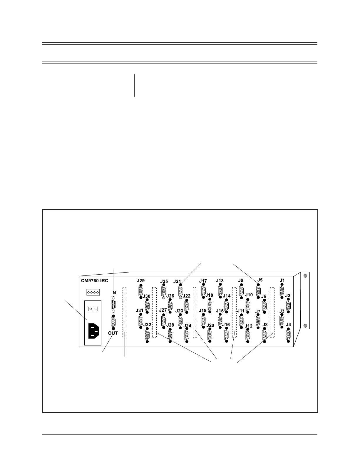
2.0 DESCRIPTION
The Pelco 9760-IRC VCR Controller provides remote control of most VCRs
equipped with an infrared receiver for controlling standard functions: play, record,
stop, fast-forward, rewind, and pause. Eject control depends on the VCR model.
This reduces the need for modifications to VCRs.
POWER
RS-422 INPUT PORT
(MALE)
RS-422 OUTPUT
PORT
(FEMALE)
COMMUNICATION CARD
Figure 1. CM9760-IRC (Rear View)
DB9 OUTPUT CONNECTIONS
(FEMALE)
CONTROL
CARDS
4 Pelco Manual C544M (2/98)
Page 5
2.1 GENERAL FEATURES
The Pelco 9760-IRC is housed in a rack frame and connects to one Sercom port on
the rear of the CM9760-CC1.
• A fully populated Pelco 9760-IRC unit consists of the following:
a. One communication card (interfaces with CM9760-CC1)
b. Four VCR control cards
• Each control card controls:
a. Up to 32 VCRs
b. Up to four different VCR brands and/or models
• Up to 128 VCRs can be controlled by one unit.
• Up to 16 IRC units can be linked in sequence (that is, daisy-chained) giving
control of up to 2,048 VCRs (refer to Figure 2)
The control cards accept messages from the CM9760-CC1 in the same manner as
a normal GPI (General Purpose Interface) relay card.
VCR control signals are transmitted by infrared control cable (IR control cable)
attached to the VCR.
128 VCRs
ANOTHER
128 VCRs
UP TO 16
UP TO TOTAL OF
2,048 VCRs
Figure 2. VCR Hook-up Parameters
Pelco Manual C544M (2/98) 5
Page 6

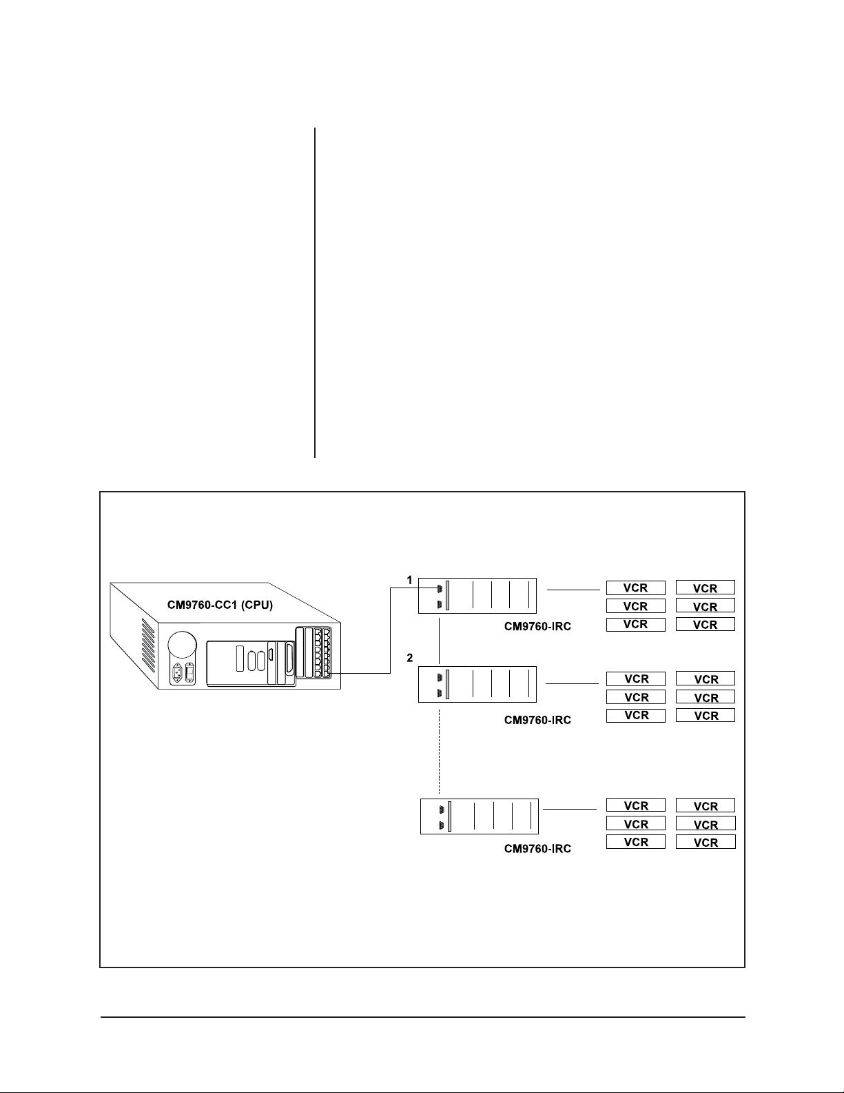
2.2 SAMPLE SYSTEM
A typical system installation involving the CM9760-IRC might include:
a. CM9760-CC1 e. Monitors
b. CM9760-IRC f. Cameras
c. CM9760-KBD g. CM9760-MXBs
d. VCRs
Other Pelco products can be added according to system requirements.
PELCO CM9760-IRC
TO IRC WITH NEXT START ADDRESS
(OR NOT CONNECTED IF IRC IS LAST IN CHAIN)
PELCO CM9760-MXB (VIDEO MATRIX BAY)
VCR CONTROL SIGNAL TO
IR LED ASSEMBLY (4 PER IRC DB9)
VIDEO SIGNAL FROM VCR “OUT” CONNECTOR (ONE PER VIDEO)
VIDEO SIGNAL FROM VCR “IN” CONNECTOR (ONE PER VIDEO)
Figure 3. Sample System Hook-up
6 Pelco Manual C544M (2/98)
Page 7

To install the Pelco Infrared VCR Controller, proceed as follows:
1. Set the baud.
2. Set the start address.
3. Connect the CM9760-IRC to the CM9760-CC1 host.
4. Connect additional IRC units in daisy-chain fashion.
5. Connect VCRs to the Video Matrix Bay (CM9760-MXB).
6. Connect the IR control cables to the VCRs.
Each step listed above is detailed below:
3.1 COMMUNICATION CARD
The communication card (refer to Figure 4) has a bank of eight DIP switches used to
do the following:
1. Set the operating baud of the unit
2. Set the start address
In Figure 5, DIP switch number 2 is ON.
3.0 INSTALLATION
COMMUNICATION CARD
Figure 4. Communication Card
Figure 5. DIP Switches
Pelco Manual C544M (2/98) 7
Page 8

3.1.1 Setting the Baud
NOTE:
The operating baud must
match the baud rate set in the .SCP
Communications File for the
CM9760-CC1.
3.2 CONTROL CARD
NOTE:
The VCRs connected to a
single microprocessor must be in the
same brand and model. Brands and
models required should be specified
at the time of order.
Bauds of 2400, 4800, 9600, and 19200 are available. The communication protocol
uses eight data bits, one stop bit, and even parity.
The baud is set using DIP switches 1 and 2 according to Table A.
Table A. Baud Settings
DIP Switch 2 DIP Switch 1 Baud
ON ON 2400
ON OFF 4800
OFF ON 9600
OFF OFF 19200
The CM9760-IRC can have up to four control cards installed.
Each control card has four microprocessors.
Each microprocessor controls two DB9 output connections.
Each DB9 output controls up to four VCRs (refer to Figure 6).
This enables one Pelco CM9760-IRC to have infrared control of 128 VCRs (that is,
four control cards multiplied by four microprocessors per card multiplied by two
DB9 outputs per microprocessor multiplied by four VCRs per DB9 output equals
128 VCRs).
CM9760-IRC
UP TO 4 CONTROL CARDS PER IRC
CM9760-CC1
2DB9 OUTPUTS PER MICROPROCESSOR
4 MICROPROCESSORS PER CARD
4 VCRs PER DB9 OUTPUT
CONTINUES UP TO
32 VCRs PER CARD
IR LED CABLES
Figure 6. The Number of VCRs Controlled by One Control Card
8 Pelco Manual C544M (2/98)
Page 9

3.2.1 Setting the Start Address
Each Pelco CM9760-IRC unit requires a six-bit start address. The start address is
configured using the DIP switches on the communication card (see Figure 5: DIP
switches). Each control card occupies one address space. An IRC unit occupies
four address spaces (if there are only two control cards in the unit, it still occupies
four address spaces).
The start address of an IRC unit is set with the DIP switches on the communication
card per Table B.
Table B. Start Addresses
DIP DIP DIP DIP DIP DIP Start Address Start Address
Switch 8 Switch 7 Switch 6 Switch 5 Switch 4 Switch 3 (Binary) (Decimal)
ON ON ON ON ON ON 000000 0
ON ON ON ON ON OFF 000001 1
ON OFF ON ON ON ON 010000 16
ON OFF ON ON OFF ON 010010 18
OFF OFF ON ON OFF ON 110010 50
OFF OFF OFF OFF OFF ON 111110 62
NOTE:
start address of the IRC as a whole.
It is necessary only to set the
Unlike an IRC unit, a serial GPI occupies one address space. In the sample system
outlined in Figure 3, the start addresses would set up according to Table C.
The start address of each control
card in the unit is set by internal default.
Table C. Start Addresses
Device Address (Decimal) Address (Binary)
Serial GPI 0 000000 Set via serial GPI communication
card DIP switches
IRC unit 1/control card 1 1 000001 Set via IRC unit 1 communication
Control card 2 2 000010 Automatic internal default
Control card 3 3 000011 Automatic internal default
Control card 4 4 000100 Automatic internal default
card DIP switches
Pelco Manual C544M (2/98) 9
Page 10

3.3 CONNECTING THE CM9760-IRC TO THE CM9760-CC1 HOST
Each CM9760-IRC has two RS-422 ports; one labeled IN (male) and the other
OUT (female).
To connect a CM9760-IRC to the CM9760-CC1 host, connect a SerCom port on
the host to the IN RS-422 port on the IRC. The data pin connections are shown
below in Figure 7.
CM9760-CC1
SERCOM
(FEMALE)
Figure 7. Pinouts for Connecting an IRC to a CPU (9760-CC1) Host
PIN 1= (TX+)
PIN 2= (TX–)
PIN 7= (RX–)
PIN 8= (RX+)
CONNECT
VIA CABLE
PIN 5= (RX+)
PIN 9= (RX–)
PIN 8= (TX–)
PIN 4= (TX+)
CM9760-IRC
RS-422 DB9 PORT
(MALE)
IN
1
2
3
4
5
6
7
8
9
10 Pelco Manual C544M (2/98)
Page 11

CM9760-CC1
SERCOM
PORTS
(FEMALE)
(ANY
SERCOM
PORT)
3.3.1 Connecting the CM9760-IRC to a CM9760-CC1 Host
via Serial GPI
A CM9760-IRC can be daisy-chained from a serial GPI already connected to a
SerCom port of a CM9760-CC1 (CPU). The wiring is the same as for Section 3.3.
Connect the RS-422 OUT port of the serial GPI to the RS-422 IN port of the IRC
(refer to Figure 8).
3.4 CONNECTING ADDITIONAL IRCs IN SEQUENCE
NOTE:
Sixteen is the maximum
number of racks that can be daisychained from one port of the host
CPU.
CM9760-IRC
RS-422 DB9 PORT
(FEMALE)
OUT
PIN 3 = (BUSY +)
PIN 7 = (BUSY –)
PIN 4 = (RX+)
PIN 8 = (RX–)
PIN 5 = (TX+)
PIN 9 = (TX–)
Figure 9. Data Pin Connections for IRC’s in Sequence
Figure 8. Connecting IRCs in Sequence
Up to 16 IRC units can be daisy-chained from one port of the CM9760-CC1 host.
The RS-422 OUT port of the first IRC must be connected to the RS-422 IN port of
the next IRC in the chain (refer to Figure 8).
The data pin connections are shown below in Figure 9.
CONNECT
VIA CABLE
PIN 3 = (BUSY +)
PIN 7 = (BUSY –)
PIN 4 = (TX+)
PIN 8 = (TX–)
PIN 5 = (RX+)
PIN 9 = (RX–)
CM9760-IRC
RS-422 DB9 PORT
(MALE)
IN
Pelco Manual C544M (2/98) 11
Page 12

CM9760-MXB
VIDEO MATRIX BAY
3.5 CONNECTING VCRs TO THE VIDEO MATRIX BAY (CM9760-MXB)
VCRs must be connected to the CM9760-MXB (Video Matrix Bay). Two standard
coaxial cables are needed:
(1) One to run from the VIDEO OUT port on the back of the VCR to the desired IN
port on the VMB.
(2) The other to run from the VIDEO IN port on the VCR to the desired OUT port
on the Video Matrix Bay.
VCR (REAR VIEW)
INPUT PORTS
(UP TO 16 CARDS, 16 PORTS PER CARD)
OUTPUT PORTS
(1 CARD, 16 PORTS PER CARD)
Figure 10. Connecting VCRs to the CM9760-MXB (Video Matrix Bay)
12 Pelco Manual C544M (2/98)
Page 13

3.6 VCR CONTROL SIGNAL OUTPUTS
An IRC has up to 32 D9 female output connections numbered J1 to J32, each able
to control four VCRs (refer to Figure 6). Every DB9 output supports four IR control
cables. Each IR control cable controls the functions of a single VCR.
The wiring for each DB9 output is shown below in Table D.
Table D. IR Control Cable Wiring
Pin IR Control Cable VCR
1 Cable 1+ VCR #1
6 Cable 1- VCR #1
2 Cable 2+ VCR #2
7 Cable 2- VCR #2
3 Cable 3+ VCR #3
8 Cable 3- VCR #3
4 Cable 4+ VCR #4
9 Cable 4- VCR #4
5
3.6.1 Transmitting VCR Commands
NOTE:
Once installation has been
completed, the appropriate programming must be made in the 9760 Configuration files (ie: SCP/.GPI/.CAM).
Connect an IR control cable to one of the DB9 infrared output connections on the
IRC. Run the cable to the target VCR.
For best results in transmitting the VCR commands (play, record, stop, fast forward, rewind, pause), the IR LED at the end of the IR control cable must be placed
directly over the receiving port on the front of the VCR.
Pelco Manual C544M (2/98) 13
Page 14

4.0 SPECIFICATIONS
Electrical Specifications
Operating
Voltages: 120 or 230 VAC 50/60 Hz.
±10%, selectable
Power
Consumption: 15 vA per control card and communication card
Operating
Temperature
Range: 32° to 122°F (0° to 50°C)
Communications
Serial
Communication
Ports: One input port, balanced RS-422
One output port, balanced RS-422
Serial
Communication
Setup
Baud rate: 2400, 4800, 9600 or 19200
Data bits: 8
Stop bits: 1
Parity bit: Even
Mechanical
Connectors: One 9-pin, DB9 input connector (male)
One 9-pin, DB9 output connector (female)
Thirty-two 9-pin, DB9 output control connectors (female)
Unit Weight: 6.61 lbs (3 kg)
Dimensions: 5.24" H x 19.02" W x 9.45" D (13.3 cm x 48.3 cm x 24.0 cm)
Type of Mounting: 19" (48.26 cm) rack mount (3 RUs)
(Design and product specifications subject to change without notice.)
This equipment contains electrical or electronic components that must be recycled properly to comply with Directive 2002/96/EC of the European Union
regarding the disposal of waste electrical and electronic equipment (WEEE). Contact your local dealer for procedures for recycling this equipment.
14 Pelco Manual C544M (2/98)
Page 15

NOTES
Pelco Manual C544M (2/98) 15
Page 16

5.0 WARRANTY AND RETURN INFORMATION
WARRANTY
Pelco will repair or replace, without charge, any merchandise proved defective in material or
workmanship for a period of one year after the date of shipment.
Exceptions to this warranty are as noted below:
• Five years on FT/FR8000 Series fiber optic products.
• Three years on Genex
• Three years on Camclosure
CC3751H-2, CC3651H-2X, MC3651H-2, and MC3651H-2X camera models, which have a fiveyear warranty.
• Two years on standard motorized or fixed focal length lenses.
• Two years on Legacy
dome products.
• Two years on Spectra
continuous motion applications.
• Two years on Esprit
• Eighteen months on DX Series digital video recorders, NVR300 Series network video
recorders, and Endura
• One year (except video heads) on video cassette recorders (VCRs). Video heads will be
covered for a period of six months.
• Six months on all pan and tilts, scanners or preset lenses used in continuous motion applications
(that is, preset scan, tour and auto scan modes).
Pelco will warrant all replacement parts and repairs for 90 days from the date of Pelco shipment.
All goods requiring warranty repair shall be sent freight prepaid to Pelco, Clovis, California. Repairs
made necessary by reason of misuse, alteration, normal wear, or accident are not covered under
this warranty.
Pelco assumes no risk and shall be subject to no liability for damages or loss resulting from the
specific use or application made of the Products. Pelco’s liability for any claim, whether based on
breach of contract, negligence, infringement of any rights of any party or product liability, relating
to the Products shall not exceed the price paid by the Dealer to Pelco for such Products. In no event
will Pelco be liable for any special, incidental or consequential damages (including loss of use, loss
of profit and claims of third parties) however caused, whether by the negligence of Pelco or
otherwise.
The above warranty provides the Dealer with specific legal rights. The Dealer may also have
additional rights, which are subject to variation from state to state.
If a warranty repair is required, the Dealer must contact Pelco at (800) 289-9100 or (559) 292-1981
to obtain a Repair Authorization number (RA), and provide the following information:
1. Model and serial number
2. Date of shipment, P.O. number, Sales Order number, or Pelco invoice number
3. Details of the defect or problem
If there is a dispute regarding the warranty of a product which does not fall under the warranty
conditions stated above, please include a written explanation with the product when returned.
Method of return shipment shall be the same or equal to the method by which the item was received
by Pelco.
®
Series products (multiplexers, server, and keyboard).
®
and fixed camera models, except the CC3701H-2, CC3701H-2X,
®
, CM6700/CM6800/CM9700 Series matrix, and DF5/DF8 Series fixed
®
, Esprit®, ExSite™, and PS20 scanners, including when used in
®
and WW5700 Series window wiper (excluding wiper blades).
™
Series distributed network-based video products.
RETURNS
In order to expedite parts returned to the factory for repair or credit, please call the factory at (800)
289-9100 or (559) 292-1981 to obtain an authorization number (CA number if returned for credit,
and RA number if returned for repair).
All merchandise returned for credit may be subject to a 20% restocking and refurbishing charge.
Goods returned for repair or credit should be clearly identified with the assigned CA or RA number
and freight should be prepaid. Ship to the appropriate address below.
If you are located within the continental U.S., Alaska, Hawaii or Puerto Rico, send goods to:
Service Department
Pelco
3500 Pelco Way
If you are located outside the continental U.S., Alaska, Hawaii or Puerto Rico and are instructed
to return goods to the USA, you may do one of the following:
Clovis, CA 93612-5699
If the goods are to be sent by a COURIER SERVICE, send the goods to:
Pelco
3500 Pelco Way
Clovis, CA 93612-5699 USA
Pelco, the Pelco logo, Camclosure, Esprit,
Genex, Legacy, and Spectra are registered
trademarks of Pelco.
Endura and ExSite are trademarks of Pelco.
© Copyright 1998, Pelco. All rights reserved.
If the goods are to be sent by a FREIGHT FORWARDER, send the goods to:
Pelco c/o Expeditors
473 Eccles Avenue
South San Francisco, CA 94080 USA
Phone: 650-737-1700
Fax: 650-737-0933
16 Pelco Manual C544M (2/98)
 Loading...