

Page 1

ADDENDUM
Addendum No.: C1577M-A
Date: August 4, 2004
Manuals Affected: CM9760 Series Manuals – C538M-A, C539M-A, C540M-B, C541M-C, C542M-B,
C543M-A, C544M, C549M-A, C572M, C573M-D, C578M, C579M, C1501M, C1503M,
C1510M-QS, C1510M-A, C1520M-B, C1528M-D, C1940M, C1941M, C1942M, and
C1943M
Manual Update: The CM9760-CC1 has been replaced with the CM9700-CC1 and the CM9760-MGR manage-
ment software has been replaced with the CM9700-MGR management software.
Keep the following in mind when referring to the instructions contained in these manuals:
• The CM9700-CC1 contains the latest CC1 software (version 9.01 or higher), and is
programmed with the new CM9700-MGR management software.
• Despite the difference in model numbers, the CM9700-CC1 functions the same as the
CM9760-CC1 and most of the information in these manuals applies to version 9.01 (or
higher) CPU.
•You can add the CM9700-CC1 to an existing CM9760 system if you upgrade the existing
CM9760-CC1 units with the current software (version level 9.01 or higher).
Software version 9.01 requires a minimum of 16 MB of RAM in the CPU. If required, you
can upgrade the RAM in older CM9760-CC1 units using the software upgrade kit
appropriate for your CPU.
• Do not use the CM9760-MGR instructions contained in these manuals. Refer to the
CM9700-MGR Getting Started Software Guide, on-screen help, or Online Help for
instructions.
Pelco World Headquarters • 3500 Pelco Way, Clovis, California 93612-5699 USA • www.pelco.com
USA & Canada: Tel: 800/289-9100 • Fax: 800/289-9150
®
International: Tel: 1-559/292-1981 • Fax: 1-559/348-1120
Page 2
®
CM9760-VCRC
VCR Controller
Installation/
Operation Manual
C1941M (7/98)
Pelco • 3500 Pelco Way • Clovis, CA 93612-5699 USA • www.pelco.com
In North America and Canada: Tel (800) 289-9100 • FAX (800) 289-9150
International Customers: Tel +1(559) 292-1981 • FAX +1(559) 348-1120
Page 3

CONTENTS
Section Page
1.0 GENERAL..................................................................................................5
1.1 IMPORTANT SAFEGUARDS AND WARNINGS ...............................5
1.2 REGULATORY NOTICES ..................................................................5
2.0 DESCRIPTION ..........................................................................................6
2.1 MODELS............................................................................................6
2.2 CERTIFICATIONS .............................................................................6
2.3 OPTIONS...........................................................................................6
3.0 PRE-INSTALLATION INFORMATION........................................................7
3.1 FRONT VIEW.....................................................................................7
3.1.1 DIP Switches .........................................................................8
3.1.1.1 DIP Switch Locations..............................................8
3.1.1.2 DIP Switch Functions .............................................8
3.1.2 LEDs ......................................................................................8
3.2 REAR VIEW .......................................................................................9
3.2.1 Input VCR Connectors ..........................................................10
3.2.2 Relay Output Connector .......................................................11
3.2.3 Communication Connectors .................................................11
3.2.3.1 DB-9 Connector Pin-outs.......................................12
3.2.3.2 RJ-45 Connector ...................................................12
3.2.4 Power Connections...............................................................13
3.3 SETUP ..............................................................................................14
3.3.1 Preliminary Discussion .........................................................14
3.3.2 DIP Switch Settings ..............................................................14
3.3.3 Software Setup–Using the MGR Program to Configure
VCRC Operation...................................................................16
4.0 INSTALLATION .........................................................................................19
4.1 DIRECT RACK-MOUNT HOOK-UP .................................................19
4.2 REMOTE OPERATION .....................................................................19
4.3 DAISY-CHAINING .............................................................................20
5.0 OPERATIONAL OVERVIEW.....................................................................21
5.1 FUNCTIONAL BLOCK DIAGRAM ....................................................21
5.2 OPERATING THE CM9760-VCRC FROM THE CM9760-KBD ........22
6.0 SPECIFICATIONS ....................................................................................23
7.0 WARRANTY AND RETURN INFORMATION ...........................................24
2 Pelco Manual C1941M (7/98)
Page 4

LIST OF ILLUSTRATIONS
Figure Page
1 Front View of CM9760-VCRC ............................................................7
2 Front Panel Removal..........................................................................7
3 DIP Switch Location...........................................................................8
4 Rear View of CM9760-VCRC.............................................................9
5 VCR Input Plugs ...............................................................................10
6 Relay Output Connector ...................................................................11
7 RJ-45 Pin-outs ..................................................................................12
8 RJ-45 Connector Pin-out Geometry .................................................12
9 Power Input Fuse Replacement........................................................13
10 DIP Switch Functions........................................................................ 15
11 Configuring MGR Camera File for VCRC Operation......................... 16
12 Configuring the GPI SETUP file for VCRC Operation.......................17
13 Configuring the COMMS file for VCRC Operation ............................18
14 CM9760-VCRC Rack-Mount Installation ..........................................19
15 Daisy-Chain Configuration ................................................................20
16 Daisy-Chain Multi-Buss Configuration ..............................................20
17 VCRC Functional Block Diagram...................................................... 21
18 CM9760-KBD VCR Control Functions ..............................................22
REVISION HISTORY
Manual # Date Comments
C1941M 7/98 Original version.
Pelco Manual C1941M (7/98) 3
Page 5

(This page intentionally left blank.)
4 Pelco Manual C1941M (7/98)
Page 6
1.0 GENERAL
1.1 IMPORTANT SAFEGUARDS AND WARNINGS
Prior to installation and use of this product, the following WARNINGS should be
observed.
1. Installation and servicing should only be done by qualified service personnel
and conform to all local codes.
2. Unless the unit is specifically marked as a NEMA Type 3, 3R, 3S, 4, 4X ,6 or
6P enclosure, it is designed for Indoor use only and it must not be installed
where exposed to rain and moisture.
3. Only use replacement parts recommended by Pelco.
4. After replacement/repair of this unit’s electrical components, conduct a resistance measurement between line and exposed parts to verify the exposed
parts have not been connected to line circuitry.
The product and/or manual may bear the following marks:
This symbol indicates that dangerous voltage constituting a
risk of electric shock is present within this unit.
This symbol indicates that there are important operating and
maintenance instructions in the literature accompanying this unit.
Please thoroughly familiarize yourself with the information in this manual
prior to installation and
operation.
CAUTION:
RISK OF
ELECTRIC SHOCK.
DO NOT OPEN.
CAUTION:
TO REDUCE THE RISK OF ELECTRICAL SHOCK,
DO NOT REMOVE COVER. NO USER-
SERVICEABLE PARTS INSIDE. REFER SERVICING
TO QUALIFIED SERVICE PERSONNEL.
1.2 REGULATORY NOTICES
NOTE: This equipment has been tested and found to comply with the limits of a
Class B digital device, pursuant to part 15 of the FCC rules. These limits are designed to provide reasonable protection against harmful interference in a residential installation. This equipment generates, uses, and can radiate radio frequency
energy and, if not installed and used in accordance with the instructions, may cause
harmful interference to radio communications. However there is no guarantee that
the interference will not occur in a particular installation. If this equipment does
cause harmful interference to radio or television reception, which can be determined by turning the equipment off and on, the user is encouraged to try and correct the interference by one or more of the following measures:
• Reorient or relocate the receiving antenna.
• Increase the separation between the equipment and the receiver.
• Connect the equipment into an outlet on a circuit different from that to which
the receiver is connected.
• Consult the dealer or an experienced radio/TV technician for help.
Pelco Manual C1941M (7/98) 5
Page 7
2.0 DESCRIPTION
The CM9760-VCRC is another optional accessory of the System 9760™. This VCRC
gives security and surveillance operators the ability to automatically or manually
control appropriate VCRs from the 9760 matrix system. It is designed to remotely
control seven basic VCR functions using two different control methods; resistive
ladder remote control and S-Link remote control.
Currently , it supports Sanyo and Sony model resistive ladder VCRs and Sony model
S-Link VCRs.
Some of the more important features of the VCR unit are as follows:
• Each unit can handle up to 64 VCRs.
• Controls seven VCR functions: play, stop, fast forward, rev erse , pause, record
and eject.
• Up to 11 units can be chained together giving a total of up to 700 VCRs controllable from a single Sercom port on the CM9760-CC1.
• VCR inputs can be configured in blocks of 16 for use by specific VCR type.
• There is one relay output per unit.
• The unit is powered by an auto-ranging power supply.
• Unique, one rack-unit chassis (1.75 inches or 4.45 cm) accommodates multiple types of mounting.
• Transparent system software operates with the CM9760-IRC as well as the
future CM9760-REL.
2.1 MODELS
CM9760-VCRC VCR control unit capable of controlling 64 VCRs per unit. VCR
control is specific to Sanyo and Sony VCRs.
2.2 CERTIFICATIONS
The products identified below have been tested and certified for agency compliance as noted.
Model CE FCC UL CSA/cUL
CM9760-VCRC X X
Applicable CE, FCC, UL, and CSA/cUL directives/standards:
• 93/68/EEC–CE Mark Directive
89/336/EEC, 92/31/EEC–Electromagnetic Compatibility (EMC) Directives
EN 55022: 1984 Class B–Radio-frequency emissions limits
EN 50082-2: 1992–Immunity standard
IEC 801-2: 1984–ESD immunity
IEC 801-3: 1984–Radiated field immunity
IEC 801-4: 1988–Electrical transients
• FCC–47 CFR, Part 15, Subpart B, Class B
Additional applicable standards:
• NEMA Type 1
• IP 20
2.3 OPTIONS
Agency Compliance Certification
CM9760-VCRC-TX A 20-foot (61 cm) VCR control cable with 1/8" jack on one end
(for connecting to VCR) and cord/shield (signal/ground) bare
wires at the opposite end for connection to input mating plugs
located on rear of VCRC.
6 Pelco Manual C1941M (7/98)
Page 8
3.0 PRE-INSTALLATION INFORMATION
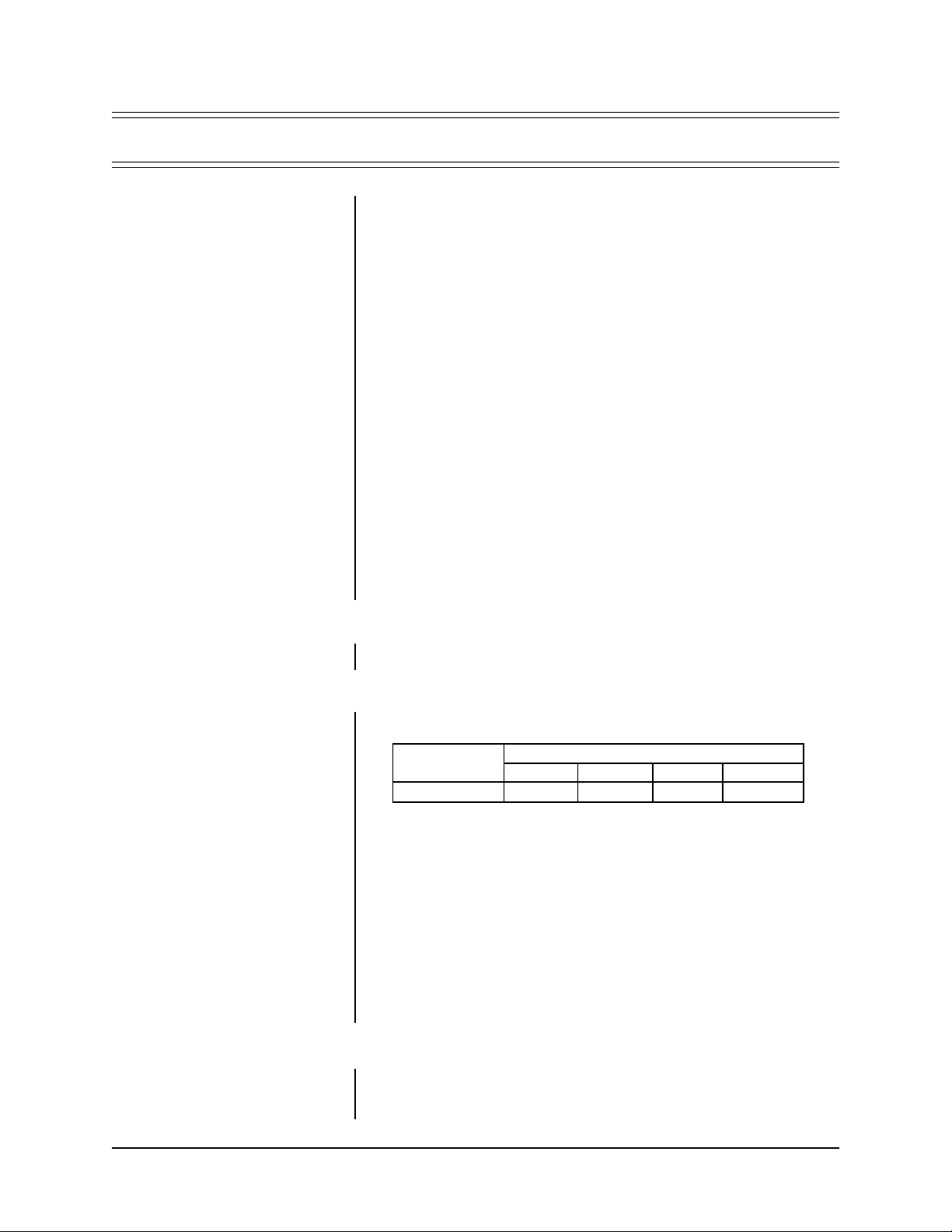
3.1 FRONT VIEW
Figure 1 illustrates the front view of the unit. P ower and data LEDs occup y opposite
ends of the front panel. The pow er LED on the left is green and the data LED on the
right is red. All other connectors, s witches, inputs and outputs are on the rear of the
unit except for two DIP switches and a reset switch located behind the front panel
cover plate.
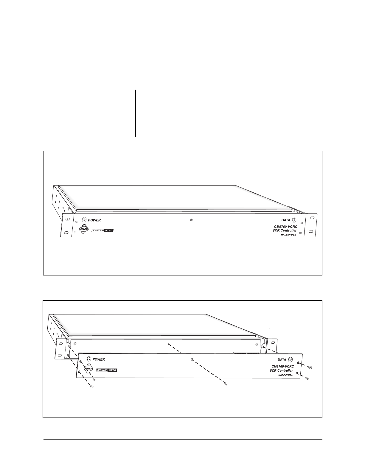
The DIP switches can be accessed easily by removing the five flat-head Phillips
screws that hold the front panel in place as illustrated in Figure 2.
Figure 1. Front View of CM9760-VCRC
Figure 2. Front Panel Removal
Pelco Manual C1941M (7/98) 7
Page 9

3.1.1 DIP Switches
With the front panel removed, DIP switch 1 and DIP s witch 2 are visib le . These two
ten-position DIP switches configure and define many functions of the CM9760VCRC.
3.1.1.1 DIP Switch Locations
Figure 3 identifies the relative locations of DIP switches 1 and 2.
3.1.1.2 DIP Switch Functions
DIP switch functions are discussed in Section 3.3, SETUP.
3.1.2 LEDs
The green POWER LED located on the left front panel of the unit comes ON at
power up.
The red DATA LED located on the right side of the front panel continually flashes on
and off at a regular rate (about 1/2 second intervals) until the first valid command is
received. The LED will not flash again until another valid command is received.
Also, in cascaded situations, if a command is meant for a VCRC further down the
chain, the command will be relayed down the chain and the LED will not come on
until the appropriate VCRC processes the command. In other words, LED activity is
address specific. Additionally, if power is cycled, or if the DIP switch slide positions
are moved, or if a front panel reset occurs, then the LED will again flash intermittently until the first valid command is received.
Figure 3. DIP Switch Location
8 Pelco Manual C1941M (7/98)
Page 10

3.2 REAR VIEW
The rear of the unit is illustrated in Figure 4. From left to right are the following:
1. The four 16-input blocks of VCR connectors in the f orm of screw-type connectors with associated mating plugs (one shown in Block 1) running from the left
rear to middle right of the unit
NOTE:
VCR b loc k ranges are assigned specific VCR type via slide
switches 7 through 10 on DIP
switch 2.
2. The VCRC output relay (one per unit)
3. RS-422 input/output communication connectors (RJ-45 type)
4. One DB-9 type connector for factory use only
5. The grouped input power functions, consisting of input power terminals, a
fuse and an ON/OFF switch
5
Figure 4. Rear Vie w of CM9760-VCRC
Pelco Manual C1941M (7/98) 9
Page 11

IMPORTANT:
Control cable
length should not be extended further than the supplied 20 feet because resistive ladder input circuits
are very susceptible to additional
line impedance. It is also recommended that shielded cable be used
to minimize external electrical interference with VCRC control signals .
See important note in Figure 9 regarding power hookup and interference.
3.2.1 Input VCR Connectors
Physically , each of the f our VCRC input connectors consists of the same n umber of
input screw-type terminals. Each input group uses a dual-row removable plug and
each plug is associated with 8 VCR inputs.
For example, ref er to the leftmost group represented in Figure 5, which sho ws VCR
inputs 1-16. Of these VCR inputs, 1-8 are wired using the top 16 screw terminal
positions. VCR inputs on this connector physically alter nate with their associated
GND connection for a total of 8 available VCR/GND connections: that is, pin 1 is
VCR input 1 and pin 2 is the GND connection associated with VCR input 1; pin 3 is
VCR input 2 and pin 4 is VCR input 2’s associated GND connection, and so on.
The same explanation applies to the lower plug for VCR inputs 9-16, starting with
VCR input 9 which is associated with physical pin 17 on the mating plug.
In a similar manner, the remaining plug (upper/lower) combinations accommodate
the three remaining VCR input blocks: that is, inputs 17-32 are handled by header
two, inputs 33-48 by header three, and inputs 49-64 by header four.
IS SHOWN IN THE TABLE BELOW.
Figure 5. VCR Input Plugs
10 Pelco Manual C1941M (7/98)
Page 12

3.2.2 Relay Output Connector
Figure 6 illustrates the relay output connector and its relative port pin assignments.
The connector is a three-position plug with screw-type contacts similar in operation
to the mating connectors just discussed.
By default, the relay is in its normal state at power up of the unit as shown in Figure
6. During operation, the relay may be toggled by controlling the 64th VCR on the
VCRC by entering VCR number 64 on the keypad, then pressing the Camera button which brings up the VCR control functions and then pressing the blue button
under the PLA Y control icon. Similarly , performing the abov e but pressing the STOP
VCR control command instead of the PLA Y command will deactiv ate the rela y. Refer to Section 5.2, OPERATING THE CM9760-VCRC FROM THE CM9760-KBD,
for more details on the operational use of the VCRC from the CM9760-KBD.
3.2.3 Communication Connectors
Communication to and from the unit is provided through two RJ-45 ports on the
rear of the CM9760-VCRC. The ports are referenced as serial port 0 and serial port 1
(refer to the functional block diagram in Figure 17).
Serial Port 0 is associated with the RJ-45 IN female connector and is configured for
RS-422 operation by default. In the configuration, the RJ-45 IN connector allows
the VCRC unit to be connected to an appropriate Sercom port on the rear of a
CM9760-CC1 controller.
Serial port 1, associated with the RJ-45 OUT connector, is always configured as
RS-422 and is used for daisy-chaining subsequent VCRC units (see Section 4.2,
REMOTE OPERATION).
Individual connector pin-outs of the communication channels are discussed next.
Figure 6. Relay Output Connector
Pelco Manual C1941M (7/98) 11
Page 13

3.2.3.1 DB-9 Connector Pin-outs
The DB-9 connector is reserved for factory use only.
3.2.3.2 RJ-45 Connector
The RJ-45 connector pin-outs are illustrated in Figure 7.
Because both RJ-45 connectors have the same wiring pin-outs, they require the
same “flipped” cab le . In other words, the IN connector requires a “flipped” cable for
connecting the first unit to the CC1, and the OUT connector requires a “flipped” for
cascading other units. A “flipped” cable is as follows: Pin 1 of the cable at one end
becomes pin 8 at the other end. Refer to Figure 8.
Note that the active pin-outs are associated with the outer four pins; namely, 1, 2, 7
and 8. All accessories on the System 9760™ require the “flipped” cable to be used
to attach peripheral equipment. This presently pertains to the KBD, MXB, CXT,
ALM, MDA, CDU-T and now the VCRC unit.
TO INTERFACE THE VCRC UNIT TO ANY SERCOM PORT ON
OR BETWEEN ONE VCRC UNIT AND ANOTHER,
Figure 7. RJ-45 Pin-outs
THE REAR OF THE CM9760-CC1
FOLLOW THE DIAGRAM BELOW:
Figure 8. RJ-45 Connector Pin-out Geometry
12 Pelco Manual C1941M (7/98)
Page 14

3.2.4 Power Connections
The CM9760-VCRC utilizes an auto-ranging internal transformer circuit that allows
the input power to range from 100-240 VAC @ 50/60 Hz. Associated with the input
power is the power ON/OFF s witch and the input power fuse. The fuse is easily changed
as illustrated in Figure 9.
IMPORTANT: IT IS IMPORTANT TO ACTIVELY
AVOID INTRODUCING CURRENT GROUND
LOOPS IN YOUR CONFIGURATIONS WHEN
HOOKING UP A VCRC AND ITS ASSOCIATED
VCRs TO POWER SOURCES. IF POSSIBLE,
HOOK EVERYTHING TO THE SAME POWER
SOURCE. SOME VCR MODELS ARE
SUSCEPTIBLE TO NOISE INTERFERENCE IN
THE LOW mV RANGE. (SEE THE IMPORTANT
NOTE ASSOCIATED WITH FIGURE 5)
SPARE FUSE
Figure 9. Pow er Input Fuse Replacement
Pelco Manual C1941M (7/98) 13
Page 15

3.3 SETUP
3.3.1 Preliminary Discussion
NOTE:
It is highly recommended
that VCRC address # 1 (F rame Address 0) be used first, VCRC address # 2 second, and so on, to
minimize programming confusion.
NOTE:
GPIs are programmed using the 9760 System Manager program. See Section 3.3.3, Software
Setup–Using the MGR Program to
Configure VCRC Operation, f or introductory instructions. For detailed
programming instructions, refer to
the Systems Manager manual.
The VCR controller (VCRC) enables automatic control (via macro execution) or
manual control (from the CM9760-KBD) of seven predefined VCR functions. Each
VCRC can control up to 64 VCRs.
VCR control is implemented by associating System 9760™ GPIs to VCRs. When a
GPI is used for VCR control, its first seven auxiliary relays are used to control the
seven most common VCR control functions. The se ven auxiliary relay numbers and
their associated VCR functions are listed below.
1. Play
2. Stop
3. Rewind
4. Fast Forward
5. Pause
6. Record
7. Eject
T wo k ey setup procedures are required in order to accomplish VCR control from the
System 9760 ™. The Frame Address Table in Figure 10 can be used as an aid to
implement both procedures.
(1) The VCR controller must be assigned an address (1 of 11) that corresponds to
a sequential range of 64 GPIs (VCRs).
Use the Frame Address Table to determine the DIP switch settings for assigning an
appropriate VCRC address setting.
(2) GPIs must be programmed in order of the 9760 CPU to communicate with the
VCRC.
Each physical GPI # corresponds to an individual VCR and its terminal connection
point on the VCRC . Theref ore , 64 GPIs must be programmed in order to control 64
VCRs from one VCRC controller.
(Figure 18 shows the relationship of these relay
numbers and the associated VCR control function
as seen on the CM9760-KBD LCD screen)
How the physical GPI # is associated with the VCRC is as follows:
• Physical GPI # 1 corresponds to the first VCR control terminal on the VCRC
that is addressed as controller # 1 (Frame Address # 0). Likewise, physical
GPI # 64 corresponds to the 64th control terminal on VCRC # 1.
• The next GPI # (the 65th) corresponds to the 1st control terminal on VCRC # 2
(Frame Address # 2). This scheme continues until the last GPI is associated
with the appropriate control terminal on the last VCRC used, which, in this
case, would be controller # 11 (Frame Address # 20).
3.3.2 DIP Switch Settings
DIP switch settings are illustrated in Figure 10.
14 Pelco Manual C1941M (7/98)
Page 16

NOTES: ANY OF THE 11 VCRCS MAY BE
ASSIGNED ANY OF THE USEABLE EVEN FRAME
ADDRESSES IN ANY ORDER YOU WISH (KEEP
IN MIND THE SPECIFIC RECOMMENDATION
MADE IN THE NOTES ON THE PREVIOUS
PAGE). JUST REMEMBER THAT THE FRAME
ADDRESS USED IS ASSOCIATED WITH A
SPECIFIC VCR RANGE. IF YOU TRY TO
CONTROL A VCR THAT DOESN'T FALL WITHIN
THE VCR RANGE, NOTHING WILL HAPPEN.
Figure 10. DIP Switch Functions
Pelco Manual C1941M (7/98) 15
Page 17

3.3.3 Software Setup–Using the MGR Program to Configure VCRC Operation
The VCRC unit controls up to 64 VCRs per unit and pro vides sev en basic functions
of VCR control direct from the CM9760 keyboard. These controls include Stop,
Pause, Play, Eject Fast Forward, Rewind and Record.
The VCRC accepts GPI commands issued under call functions of VCR control via
direct key entry or through properly prepared Macros. Access to GPI functionality is
setup in the MGR program in the following manner . What follows is a brief introduction to just those files which need to be programmed for successful VCRC operation and does not address other items that might be needed for your particular
system operation. Consult your MGR manual and associated software for other
specific or more detailed information.
On a separate PC and monitor start the 9760-MGR Setup program and access the
Camera File (.CAM file). Refer to Figure 11.
NOTE:
It is a good idea to use the
same number for the assigned GPI
as is used for the camera (VCR).
This leads to less confusion later
when calling up the camera (VCRs)
from the keyboard that are associated here with a GPI. In other
words, associate camera #1 with a
GPI connect of 1, camera #2 with
a GPI connect of 2 and so on. Also
set the logical and physical numbers for cameras (VCRs) equal to
each other.
1. Select the desired physical camera input that will be associated as a VCR.
2. Program a logical input number, title identification (Ident), and operator access (Oper Acc) for the associated VCR selected in the previous step.
3. Access the tab labeled “Type” and select VCR as the input type.
4. Highlight the GPI box and input a GPI number that corresponds to a specific
VCR control signal on the VCR controller.
5. Continue to program all desired inputs as VCRs b y repeating steps 1-4. Up to
700 VCRs can be defined.
6. When all cameras (VCRs) are defined and associated “Connect GPIs” are
assigned, save the camera file and click on the GPI tab in the main menu of
the MGR program.
Figure 11. Configuring MGR Camera File for VCRC Oper ation
16 Pelco Manual C1941M (7/98)
Page 18

NOTE:
When writing macros to
control VCR operation, keep in
mind the following:
The macro must reflect your actual
equipment configuration; if you
change the configuration, you must
adjust the macro accordingly. For
example, if a macro were written
to control VCRs attached to three
VCRCs in a daisy-chained configuration and one of the VCRCs was
subsequently removed, then any
previously written macro that included these three VCRCs would
have to be rewritten to reflect that
change. Similarly, changing the
frame address setting via SW2 on
any of the three VCRCs w ould have
the same effect as physically removing the unit from the configuration (as far as the macro is concerned) and, as before, the macro
must be edited or rewritten to reflect any changes made.
7. This brings up the GPI SETUP file dialog box (.GPI file). Refer to Figure 12.
8. Program logical GPI numbers for all the physical numbers that will be used.
The physical GPI numbers correspond to a specific VCR control signal on the
VCR controller. Also, these GPI numbers correspond with the “Connect GPI”
numbers entered previously in the camera file.
9. For each associated GPI defined here, make sure none of the relay boxes
have been checked. In other words, define all relays as momentary.
Figure 12. Configuring the GPI SETUP file for VCRC Oper ation
Pelco Manual C1941M (7/98) 17
Page 19

10. Define operator access, save the GPI file, return to the MGR main menu screen
and press the tab to bring up the COMMS file (.SCP file). Refer to Figure 13.
11. In the COMMs file assign an equipment number “17” to the port on the CC1
that will be used for communicating to the VCRC. Also, set communication
settings for 9600 baud and even parity. Save the COMMs file, back out of the
MGR program and transfer all appropriate configuration files to disk and load
these files onto the CC1 to which your VCRC configuration is attached. You
should now be ready to operate your VCR via direct control from the CM9760KBD.
Figure 13. Configuring the COMMS file for VCRC Operation
18 Pelco Manual C1941M (7/98)
Page 20

Physical installation of the VCRC unit is relatively simple, although v arious configurations are possible.
4.1 DIRECT RACK-MOUNT HOOK-UP
Regardless of the location of a VCRC unit, it will more than likely be installed in a
rack (refer to Figure 14). The VCRC unit mounts in a standard 19-inch (48.26 cm)
rack and occupies only one RU (1.75" or 4.45 cm) of rack space.
4.2 REMOTE OPERATION
If it is desired or necessary to place the VCRC unit some distance from the controller (CM9760-CC1), the wiring run from the CC1 to the RJ-45 IN port should not
exceed 4,000 feet (1,219 m).
4.0 INSTALLATION
Figure 14. CM9760-VCRC Rack-Mount Installation
Pelco Manual C1941M (7/98) 19
Page 21

4.3 DAISY-CHAINING
Up to eleven VCRCs may be daisy-chained together. This enables the system to
support up to 700 VCRs. Figure 15 illustrates the required wiring connections for
daisy-chaining.
Note that the remarks made in the previous section regarding RS-422 wiring run
distances also applies here when considering cables distance runs between daisychained units.
Since the VCRC units utilize the same protocol as that f or GPIs, they can be b ussed
together with CM9760-IRCs, and in the future with CM9760-RELs. Figure 16 illustrates this configuration.
ANY OF THE ELEVEN UNITS REFERENCED BELOW CAN BE ASSIGNED ANY OF THE 11 FRAME
ADDRESS RANGES AVAILABLE. FRAME ADDRESSES DO NOT HAVE TO BE SEQUENTIAL. THIS
MEANS UNIT 11 IN THE DIAGRAM BELOW, FOR EXAMPLE, CAN BE ASSIGNED FRAME ADDRESS 2,
WHILE UNIT 3 IS ASSIGNED FRAME ADDRESS 10.
Figure 15. Daisy-Chain Configuration
CM9760-IRC CM9760-REL
Figure 16. Daisy-Chain Multi-Buss Configuration
20 Pelco Manual C1941M (7/98)
Page 22

5.0 OPERATIONAL OVERVIEW
The basic function of the VCRC unit is to act as an interface between the user/
operator of the system and any connected VCRs. Each VCRC processes and executes only commands with addresses that match the controller address. When a
VCRC receives a command with an inappropriate address it passes it on to the
next unit (if applicable) via its OUT port.
When power is first applied to the unit, RAM is cleared and initialization routines are
called. The power LED is lit, operational chips are configured, interrupt priorities are
set and the activity LED on the front panel of the unit flashes on and off at about
1/2 second intervals. LED activity is detailed in Section 3.1.2, LEDs. The unit is
waiting for its first valid command.
5.1 FUNCTIONAL BLOCK DIAGRAM
The block diagram below represents a combination of internal circuitry as well as
software controlled hardware within the CM9760-VCRC unit.
Figure 17. VCRC Functional Bloc k Diag ram
Pelco Manual C1941M (7/98) 21
Page 23

5.2 OPERATING THE CM9760-VCRC FROM THE CM9760-KBD
Direct control operation of VCRs attached to VCRCs from a CM9760-KBD is relatively straightforward. Once the system is running and the keyboard is on-line, direct control of a VCR is as follows:
1. Select an input (camera) that was programmed as a VCR on the keyboard.
This will cause the keyboard’s LCD to change to the VCR control menu illustrated in Figure 18.
2. Activate a VCR function b y pressing the blue b utton directly below the desired
function’s icon. All VCR functions require only a momentary ke y press for activation.
3. Control additional VCRs by repeating steps 1 and 2.
Figure 18. CM9760-KBD VCR Control Functions
22 Pelco Manual C1941M (7/98)
Page 24

6.0 SPECIFICATIONS
Electrical
Input Voltage: Auto-ranging 100-240 VAC, 50/60 Hz
Power: Consumption: 30 vA
Data Ports
Input: RS-422, RJ-45 connector
DIP switch selectable baud rate
Output: RS-422, RJ-45 connector.
Output: DB-9 connector
Indicators: 2 power LEDs, green
Fusing: 500 mA, 250 V
Relay Out: Load rating for relay contacts:
General
Dimensions 19.37" W x 1.73" H x 8.15" D (49.2 cm x 4.4 cm x 20.7 cm)
Operating
Temperature: 32°F to 158°F (0°C to 70°C)
Weight: 7 lb (3.17 kg)
Mechanical
Connectors
VCRC Input: Four dual-header, 32 input connectors with mating plugs
Power: 3-wire, #18 AWG
RS-422: Two RJ-45 connectors
RS-232: One DB-9 connector
Relay Out: One 3-pin header with mating plug
DIP switch selectable baud rate
Factory use only
1 activity LED, red
0.50 A at 125 VAC or 1 A at 24 VDC
(Design and product specifications subject to change without notice.)
Pelco Manual C1941M (7/98) 23
Page 25

7.0 WARRANTY AND RETURN INFORMATION
WARRANTY
Pelco will repair or replace, without charge, any merchandise proved defective in material or
workmanship for a period of one year after the date of shipment.
Exceptions to this warranty are as noted below:
Pelco, the Pelco logo, Camclosure, Esprit, Genex,
Legacy, Spectra, CM9760, and PelcoVision are
registered trademarks of Pelco.
Endura and ExSite are trademarks of Pelco.
© Copyright 1998, Pelco. All rights reserved.
• Five years on FT/FR8000 Series fiber optic products.
• Three years on Genex
• Three years on Camclosure
2X, CC3751H-2, CC3651H-2X, MC3651H-2, and MC3651H-2X camera models, which have
a five-year warranty.
• Two years on standard motorized or fixed focal length lenses.
• Two years on Legacy
dome products.
• Two years on Spectra
continuous motion applications.
• Two years on Esprit
• Eighteen months on DX Series digital video recorders, NVR300 Series network video
recorders, and Endura
• One year (except video heads) on video cassette recorders (VCRs). Video heads will be
covered for a period of six months.
• Six months on all pan and tilts, scanners or preset lenses used in continuous motion
applications (that is, preset scan, tour and auto scan modes).
Pelco will warrant all replacement parts and repairs for 90 days from the date of Pelco shipment.
All goods requiring warranty repair shall be sent freight prepaid to Pelco, Clovis, California.
Repairs made necessary by reason of misuse, alteration, normal wear, or accident are not
covered under this warranty.
Pelco assumes no risk and shall be subject to no liability for damages or loss resulting from the
specific use or application made of the Products. Pelco’s liability for any claim, whether based
on breach of contract, negligence, infringement of any rights of any party or product liability,
relating to the Products shall not exceed the price paid by the Dealer to Pelco for such Products.
In no event will Pelco be liable for any special, incidental or consequential damages (including
loss of use, loss of profit and claims of third parties) however caused, whether by the negligence
of Pelco or otherwise.
The above warranty provides the Dealer with specific legal rights. The Dealer may also have
additional rights, which are subject to variation from state to state.
If a warranty repair is required, the Dealer must contact Pelco at (800) 289-9100 or (559) 2921981 to obtain a Repair Authorization number (RA), and provide the following information:
1. Model and serial number
2. Date of shipment, P.O. number, Sales Order number, or Pelco invoice number
3. Details of the defect or problem
If there is a dispute regarding the warranty of a product which does not fall under the warranty
conditions stated above, please include a written explanation with the product when returned.
Method of return shipment shall be the same or equal to the method by which the item was
received by Pelco.
RETURNS
In order to expedite parts returned to the factory for repair or credit, please call the factory at (800)
289-9100 or (559) 292-1981 to obtain an authorization number (CA number if returned for credit,
and RA number if returned for repair).
All merchandise returned for credit may be subject to a 20% restocking and refurbishing charge.
Goods returned for repair or credit should be clearly identified with the assigned CA or RA number
and freight should be prepaid. Ship to the appropriate address below.
If you are located within the continental U.S., Alaska, Hawaii or Puerto Rico, send goods to:
Service Department
Pelco
3500 Pelco Way
Clovis, CA 93612-5699
If you are located outside the continental U.S., Alaska, Hawaii or Puerto Rico and are instructed
to return goods to the USA, you may do one of the following:
If the goods are to be sent by a COURIER SERVICE, send the goods to:
Pelco
3500 Pelco Way
Clovis, CA 93612-5699 USA
If the goods are to be sent by a FREIGHT FORWARDER, send the goods to:
Pelco c/o Expeditors
473 Eccles Avenue
South San Francisco, CA 94080 USA
Phone: 650-737-1700
Fax: 650-737-0933
®
Series products (multiplexers, server, and keyboard).
®
and fixed camera models, except the CC3701H-2, CC3701H-
®
, CM6700/CM6800/CM9700 Series matrix, and DF5/DF8 Series fixed
®
, Esprit®, ExSite™, and PS20 scanners, including when used in
®
and WW5700 Series window wiper (excluding wiper blades).
™
Series distributed network-based video products.
24 Pelco Manual C1941M (7/98)
 Loading...