

Page 1
®
Installation/Operation
KBD100
Universal Keyboard
C529M-D (9/03)
F
1
MON ACK PREV NEXT HOLD MACRO PGM
7
0
CLEARCAM
4
8
M
1
K
B
D
A
D
E
IN
U
S
23
5
6
9
200
A
.
F
SEQUENCE
2
F
3
Pelco
• 3500 Pelco Way • Clovis, CA 93612-5699 USA •
www.pelco.com
In North America and Canada: Tel (800) 289-9100 • FAX (800) 289-9150
International Customers: Tel +1(559) 292-1981 • FAX +1(559) 348-1120
Page 2

CONTENTS
REGULATORY NOTICES .................................................................................................................. 2
IMPORTANT SAFEGUARDS AND WARNINGS ............................................................................... 3
DESCRIPTION .................................................................................................................................. 3
INSTALLATION .................................................................................................................................. 4
Connecting a Keyboard to the Local Keyboard Port ..................................................................... 4
Connecting Keyboards to the Remote Keyboard(s) Port .............................................................. 4
SWITCH SETTINGS .......................................................................................................................... 6
PROGRAMMING AND OPERATION ................................................................................................. 8
SPECIFICATIONS ............................................................................................................................ 10
INDEX ............................................................................................................................................... 11
WARRANTY AND RETURN INFORMATION ................................................................................... 12
LIST OF ILLUSTRATIONS
1 KBD100 Application ................................................................................................................. 3
2 Keyboard Cabling Diagram ...................................................................................................... 5
3 Wiring Diagram for Remote Keyboards ................................................................................... 5
4 Keyboard Rear Panel ............................................................................................................... 7
5 Keyboard Functions ................................................................................................................. 9
LIST OF TABLES
A KBD100 Operational Functions................................................................................................ 3
B Keyboard Addresses ................................................................................................................ 6
C Keyboard Definitions for KBD100 ............................................................................................ 8
D KBD100 Button Functions ........................................................................................................9
REGULATORY NOTICES
Note: This equipment has been tested and found to comply with the limits of a Class A digital device, pursuant to part 15 of the FCC rules. These limits are designed to provide reasonable protection against harmful interference when the equipment is operated in a commercial environment.
This equipment generates, uses, and can radiate radio frequency energy and, if not installed and
used in accordance with the instruction manual, may cause harmful interference to radio communications. Operation of this equipment in a residential area is likely to cause harmful interference in
which case the user will be required to correct the interference at his own expense.
[
]
2
Pelco Manual C529M-D (9/03)
Page 3
IMPORTANT SAFEGUARDS AND WARNINGS
Prior to installation and use of this product, the following WARNINGS should be observed.
1. Installation and servicing should only be done by qualified service personnel and conform to all local
codes.
2. This unit is designed for indoor use only and must not be installed where exposed to rain and moisture.
3. Use only replacement parts recommended by Pelco.
4. After replacement/repair of this unit’s electrical components, conduct a resistance measurement between line and exposed parts to verify the exposed parts have not been connected to line circuitry.
Please thoroughly familiarize yourself with the information in this manual prior to installation and operation.
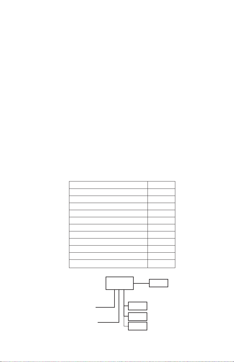
DESCRIPTION
The KBD100 Universal Keyboard is used to program and operate a CM6700 Matrix Switcher/Controller Unit
(SCU).
The KBD100 provides economical system control and programming capability to locations that do not require the complete camera control abilities of the KBD200 and KBD300 Series keyboards. Table A lists
the operational functions of the KBD100 keyboard.
Table A. KBD100 Operational Functions
Function Availability
Select cameras Yes
Select monitors Yes
Control lenses No
Set and call presets/patterns No
Control receiver auxiliaries No
Control switcher auxiliaries Yes
Control multiplexer No
Control CM6700 Matrix Switcher Yes
Program CM6700 Matrix Switcher Yes
Sequencing Yes
Operate frame, auto, and random scans No
FROM
CAMERAS
TO
MONITORS
Figure 1. KBD100 Application
CM6700
REMOTE
PORT
KBD100
KBD100
KBD100
LOCAL
PORT
KBD100
REMOTE
KEYBOARDS
Pelco Manual C529M-D (9/03)
[
]
3
Page 4

INSTALLATION
There are two keyboard ports on the CM6700 Switcher/Control Unit (SCU).
The LOCAL KEYBOARD port is for connecting a single keyboard within a distance of 25 feet (7.6 meters).
The REMOTE KEYBOARD(S) port is for connecting additional remote keyboards.
Connecting a Keyboard to the Local Keyboard Port
1 Use the data cable that is supplied with the keyboard. Plug one end of the cable into the RJ-45 con-
nector on the rear of the keyboard and the other end into the LOCAL KEYBOARD port on the SCU
(refer to Figure 2). Set the keyboard address according to Table B on page 6.
Go to step 2 to install remote keyboards, or go to step 10.
Connecting Keyboards to the Remote Keyboard(s) Port
NOTE:
A KBDKIT or KBDKIT-X is required for this application. The KBDKIT consists of two RJ-45 wall
blocks and 120 VAC to 12 VAC transformers. The KBDKIT-X is for 230 VAC. Use one wall block for each
keyboard.
Refer to Figures 2 and 3 for the following steps.
2 Select a suitable location for each keyboard and wall block. Wall blocks must be within 6 feet (1.8 m)
of a suitable electrical outlet. Do not mount the wall block yet.
3 Run wall block interconnect cable (user-supplied) from the SCU to the closest keyboard location, then
to the next nearest location, and the next, etc.
Communication to the keyboards is RS-485. Maximum cable distance for RS-485 communication over
24-gauge wire is 4,000 feet (1,219 m). Pelco recommends using shielded twisted pairs cable that meets
or exceeds the basic requirements for EIA RS-485 applications.
4 Remove the wall block cover and make cable connections at each wall block according to Figure 3.
5 At each wall block, wire the transformer to pins 3 and 4. Polarity is unimportant.
6 Replace the cover on the wall block. Secure the wall block to a suitable surface. A double-sided sticky
pad is provided to mount the wall block.
7 Set the address switches for each keyboard according to the instructions on page 6.
8 Plug in all keyboard data cables according to Figure 2.
9 Plug the KBDKIT or KBDKIT-X transformers into a suitable outlet.
10 To initialize the keyboard, wait five seconds after power-up, enter the number for the monitor you are
viewing (1-4), and press MON. The LED display shows the number selected.
NOTE:
You must re-initialize whenever power is cycled.
11 Go to the
[
]
4
Programming and Operation
Pelco Manual C529M-D (9/03)
Section and program and test for proper operation.
Page 5

USER-SUPPLIED CABLE
6
LOCAL
KEYBOARD
25-FOOT KEYBOARD DATA CABLE
NOTE: A SEPARATE PATH MUST BE PROVIDED
FOR VIDEO TO THE MONITOR.
CM6700
3
REPLACE
COVER
KBD
ADDITIONAL
KEYBOARDS
REPLACE
6
COVER
LOCAL
KEYBOARD
1
KBDKIT
LOCAL
KBD
2
8
25-FOOT KEYBOARD
DATA CABLE
Figure 2. Keyboard Cabling Diagram
R+R-T-T+
USER-SUPPLIED CABLE
7
8
REMOTE KEYBOARDS
RJ-45 WALL BLOCK TERMINALS
4 4
TERMINAL
TX+
TX-
AC
5 5
AC
GND
RX-
RX+
KBD
2
25-FOOT KEYBOARD
DATA CABLE
45
3
6
2
7
1
8
1
2
3
4
5
6
7
8
TX+
TX-
AC
AC
GND
RX-
RX+
12 VAC12 VAC
SET SWITCHES
(PAGE 6)
TERMINAL
1
2
3
4
5
6
7
8
7
9 9
Figure 3. Wiring Diagram for Remote Keyboards
Pelco Manual C529M-D (9/03)
[
]
5
Page 6

SWITCH SETTINGS
To set the switches on the keyboard (refer to Figure 4):
1 Remove the two screws and the DIP switch cover plate from the rear of the keyboard.
2 Set the switches:
Address (Switches 1-4)
Keyboard Address Switch Settings
Position the switches according to Table B. Each keyboard in the system must have a different address. To make programming easier, address keyboards in ascending order.
NOTE:
You may use a total of 8 different addresses between 1 and
16 with the CM6700 SCU.
Table B. Keyboard Addresses
1234
1 0 OFF OFF OFF OFF
2 1 ON OFF OFF OFF
3 2 OFF ON OFF OFF
4 3 ON ON OFF OFF
5 4 OFF OFF ON OFF
6 5 ON OFF ON OFF
7 6 OFF ON ON OFF
8 7 ON ON ON OFF
9 8 OFF OFF OFF ON
10 9 ON OFF OFF ON
11 10 OFF ON OFF ON
12 11 ON ON OFF ON
13 12 OFF OFF ON ON
14 13 ON OFF ON ON
15 14 OFF ON ON ON
16 15 ON ON ON ON
3 Replace the cover plate.
[
]
6
Pelco Manual C529M-D (9/03)
Page 7

REMOVE DIP
1
SWITCH COVER PLATE
KEYBOARD
DATA
2
ON
1234
KEYBOARD
DIP SWITCH
Figure 4. Keyboard Rear Panel
3
REPLACE
COVER
Pelco Manual C529M-D (9/03)
[
]
7
Page 8

PROGRAMMING AND OPERATION
Programming and operation of each function is explained in Tables C and D. Refer to Figure 5 for the location of keys.
Table C. Keyboard Definitions for KBD100
Function Procedure
Select Camera
Select Monitor
Sequence
Macro Sequence
Auxiliaries/Relays
Enter camera number (1-16) 8 and press CAM 7 to select.
NOTE:
The CM6700 can be programmed to restrict some monitors from
viewing certain cameras. To display a camera’s view on your monitor, be sure
that your keyboard shows the number of the monitor you are viewing and be
sure that the CM6700 has not been programmed to restrict viewing of that
camera.
LED display 1 shows monitor number in run mode.
Enter monitor number (1-4) 8 and press MON 10 to select.
Sequence steps through all 16 cameras. Camera number, camera title, sequence status, and time/date are shown on the monitor.
Press PREV 2A to step back one camera. Hold for two seconds for a backward sequence. Monitor shows B. Press during sequence to speed up. Press
during a forward sequence to reverse.
Press NEXT 2B to step forward one camera. Hold for two seconds for a forward sequence. Monitor shows F. Press during sequence to speed up. Press
during a backward sequence to go forward.
Press HOLD 2C to hold a sequence. Monitor shows H. Press PREV or NEXT
to resume.
Manually select a camera or press CAM 7 to turn off a sequence. Monitor shows O.
Enter 1 or 2 8 and press MACRO 5 to start a group camera sequence. Monitor shows M. Refer to the CM6700 manual for macro/sequence programming.
F1-F3 3 control only the auxiliaries built into the CM6700 SCU.
These outputs can be programmed for momentary, keyed, latched, or alarm
operation. See the CM6700 SCU manual for programming instructions.
F1: Activate/deactivate switcher auxiliary 1 relay.
F2: Activate/deactivate switcher auxiliary 2 TTL output.
F3: Activate/deactivate switcher auxiliary 3 TTL output.
Acknowledge Alarm
Program (CM6700)
LED
Clear
[
]
8
Pelco Manual C529M-D (9/03)
Press ACK 9 to acknowledge an alarm. Refer to the CM6700 manual for further information on alarms.
To program the CM6700 switcher, press PGM 4 . Follow the programming
procedure in the CM6700 manual. LED Display 1 shows P in program mode.
Press ACK 9 to exit.
LED 1 shows monitor number or P (in program mode).
Press CLEAR 6 to cancel a number that has been entered.
Page 9

10
2
B
2
2
1
A
C
3
4
F1 F2 F3
SEQUENCE
MON ACK PREV NEXT HOLD MACRO PGM
9
1
4
7
23
6
5
9
8
0
CLEARCAM
KBD100
MADE IN USA.
5
8
7
Figure 5. Keyboard Functions
Table D. KBD100 Button Functions
Reference Description
Number
1 LED display
2A-2C Sequence keys: Previous, Next, Hold
3 Function keys F1, F2, F3 control auxiliaries
4 Program key
5 Macro sequence key
6 Clear key
7 Camera selection key
8 Keypad (numbers 1 through 0)
9 Acknowledge key
10 Monitor selection key
6
Pelco Manual C529M-D (9/03)
[
]
9
Page 10

SPECIFICATIONS
GENERAL
Keyboard Keypad: Electromechanical
Digital Display: Red LED, 7-segment, 2 cells
Ambient Operating
Temperature: 20° to 120°F (-7° to 49°C)
Humidity: 10-90% non-condensing
Dimensions: 6.00 (W) x 7.125 (D) x 2.25 (H) inches (15.24 x 18.10 x 5.72 cm)
Weight: 1.9 lb (0.86 kg)
ELECTRICAL
Input Voltage: 12 VAC or ±12 VDC
Power Consumption: 5 watts
Connector Type: RJ-45, 8-pin modular (female)
Keyboard Communication
Interface: RS-485
Protocol: Pelco ASCII
Baud: 9600
Communication Parameters: 8 data bits, odd parity, 1 stop bit
(Design and product specifications subject to change without notice.)
This equipment contains electrical or electronic components that must be recycled properly to comply with
This equipment contains electrical or electronic components that must be recycled properly to comply with Directive 2002/96/EC of the European Union
regarding the disposal of waste electrical and electronic equipment (WEEE). Contact your local dealer for procedures for recycling this equipment.
Directive 2002/96/EC of the European Union regarding the disposal of waste electrical and electronic
equipment (WEEE). Contact your local dealer for procedures for recycling equipment.
[
]
10
Pelco Manual C529M-D (9/03)
Page 11

INDEX
A
Acknowledge Alarm 8
Auxiliaries 8
C
Clear 8
D
Description 3
DIP switch 6
I
Installation 4
K
KBDKIT 4
KBDKIT-X 4
Keyboard Addresses 6
L
LED 8
M
Macro Sequence 8
O
Operation 8
Operation functions 8
P
Program CM6700 8
Programming 8
R
Regulatory notices 2
Relays 8
Returns 12
RS-485 cable distance 4
S
Safeguards 3
Select Camera 8
Select Monitor 8
Sequence 8
Specifications 10
Switch Settings 6
W
Wall block 4
Warranty 12
Pelco Manual C529M-D (9/03)
[
11
]
Page 12

WARRANTY AND RETURN INFORMATION
PRODUCT WARRANTY AND RETURN INFORMATION
WARRANTY
Pelco will repair or replace, without charge, any merchandise proved defective in material or workmanship for a period of one year after the date of
shipment.
Exceptions to this warranty are as noted below:
• Five years on FT/FR8000 Series fiber optic products.
• Three years on Genex
• Three years on Camclosure
MC3651H-2X camera models, which have a five-year warranty.
• Two years on standard motorized or fixed focal length lenses.
• Two years on Legacy
• Two years on Spectra
• Two years on Esprit
• Eighteen months on DX Series digital video recorders, NVR300 Series network video recorders, and Endura
products.
• One year (except video heads) on video cassette recorders (VCRs). Video heads will be covered for a period of six months.
• Six months on all pan and tilts, scanners or preset lenses used in continuous motion applications (that is, preset scan, tour and auto scan modes).
Pelco will warrant all replacement parts and repairs for 90 days from the date of Pelco shipment. All goods requiring warranty repair shall be sent freight
prepaid to Pelco, Clovis, California. Repairs made necessary by reason of misuse, alteration, normal wear, or accident are not covered under this
warranty.
Pelco assumes no risk and shall be subject to no liability for damages or loss resulting from the specific use or application made of the Products. Pelco’s
liability for any claim, whether based on breach of contract, negligence, infringement of any rights of any party or product liability, relating to the Products
shall not exceed the price paid by the Dealer to Pelco for such Products. In no event will Pelco be liable for any special, incidental or consequential
damages (including loss of use, loss of profit and claims of third parties) however caused, whether by the negligence of Pelco or otherwise.
The above warranty provides the Dealer with specific legal rights. The Dealer may also have additional rights, which are subject to variation from state
to state.
If a warranty repair is required, the Dealer must contact Pelco at (800) 289-9100 or (559) 292-1981 to obtain a Repair Authorization number (RA), and
provide the following information:
1. Model and serial number
2. Date of shipment, P.O. number, Sales Order number, or Pelco invoice number
3. Details of the defect or problem
If there is a dispute regarding the warranty of a product which does not fall under the warranty conditions stated above, please include a written
explanation with the product when returned.
Method of return shipment shall be the same or equal to the method by which the item was received by Pelco.
®
Series products (multiplexers, server, and keyboard).
®
and fixed camera models, except the CC3701H-2, CC3701H-2X, CC3751H-2, CC3651H-2X, MC3651H-2, and
®
, CM6700/CM6800/CM9700 Series matrix, and DF5/DF8 Series fixed dome products.
®
, Esprit®, ExSite™, and PS20 scanners, including when used in continuous motion applications.
®
and WW5700 Series window wiper (excluding wiper blades).
™
Series distributed network-based video
RETURNS
In order to expedite parts returned to the factory for repair or credit, please call the factory at (800) 289-9100 or (559) 292-1981 to obtain an authorization
number (CA number if returned for credit, and RA number if returned for repair).
All merchandise returned for credit may be subject to a 20% restocking and refurbishing charge.
Goods returned for repair or credit should be clearly identified with the assigned CA or RA number and freight should be prepaid. Ship to the appropriate
address below.
If you are located within the continental U.S., Alaska, Hawaii or Puerto Rico, send goods to:
Service Department
Pelco
3500 Pelco Way
Clovis, CA 93612-5699
If you are located outside the continental U.S., Alaska, Hawaii or Puerto Rico and are instructed to return goods to the USA, you may do one of the
following:
If the goods are to be sent by a COURIER SERVICE, send the goods to:
Pelco
3500 Pelco Way
Clovis, CA 93612-5699 USA
Pelco, the Pelco logo, Camclosure, Esprit, Genex, Legacy, and Spectra are registered trademarks of Pelco.
Endura and ExSite are trademarks of Pelco.
© Copyright 2000, Pelco. All rights reserved.
If the goods are to be sent by a FREIGHT FORWARDER, send the goods to:
Pelco c/o Expeditors
473 Eccles Avenue
South San Francisco, CA 94080 USA
Phone: 650-737-1700
Fax: 650-737-0933
REVISION HISTORY
Manual # Date Comments
C529M 7/97 Original version.
C529M-A 12/97 Revision a. Revised installation instructions.
C529M-B 5/98 Revised installation instructions as a result of hardware changes to the rear panel of the
CM6700 SCU. Removed references to KBD100-X because model has been replaced with
KBDKIT-X. Changed manual pagination.
6/98 Added Section 1.2, Regulatory Notices and Section 2.2, Certifications.
10/98 Revised Table A.
C529M-C 8/00 Revised format.
C529M-D 9/03 Added uL certification seal. Changed power consumption specification.
[
]
12
Pelco Manual C529M-D (9/03)
 Loading...