

Page 1
INSTALLATION/OPERATION
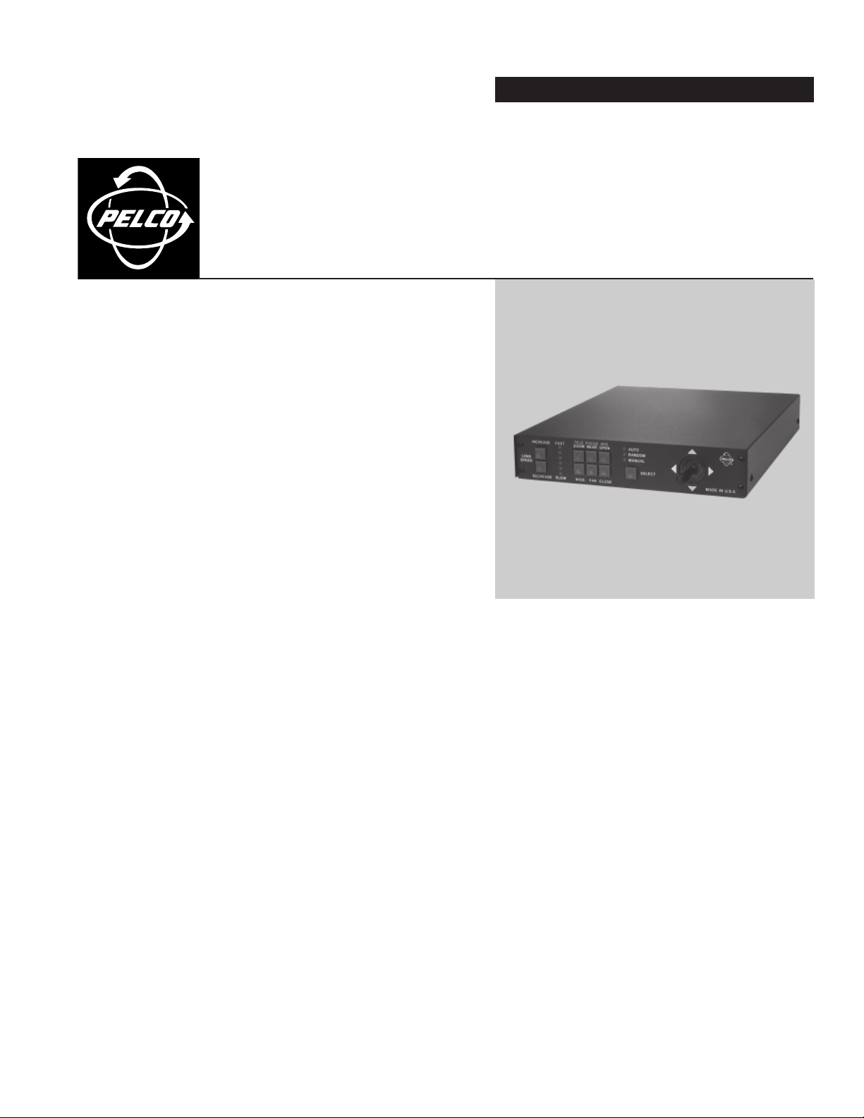
MPTAZ Series Pan/Tilt
®
and Scanner Control
C528M-E (4/03)
Page 2

CONTENTS
Section Page
IMPORTANT SAFEGUARDS AND WARNINGS .................................................................................................................................................................. 3
DESCRIPTION ..................................................................................................................................................................................................................... 4
MODELS .................................................................................................................................................................................................................... 4
INSTALLATION .................................................................................................................................................................................................................... 5
OPERATION......................................................................................................................................................................................................................... 8
MAINTENANCE .................................................................................................................................................................................................................. 9
SPECIFICATIONS................................................................................................................................................................................................................ 10
REGULATORY NOTICES ..................................................................................................................................................................................................... 11
WARRANTY AND RETURN INFORMATION ......................................................................................................................................................................11
LIST OF ILLUSTRATIONS
Figure Page
1 PC Board Configuration .................................................................................................................................................................................... 5
2 MPTAZ24DT, MPTAZ24DT/220 Wiring Diagram for Scanners and Lenses ..................................................................................................... 6
3 MPTAZ24DT, MPTAZ24DT/220 Wiring Diagram for Pan/Tilts and Lenses ..................................................................................................... 6
4 Connector Assembly .........................................................................................................................................................................................7
5 MPTAZ115DT, MPTAZ220DT Wiring Diagram for Scanners and Lenses ........................................................................................................ 7
6 MPTAZ115DT, MPTAZ220DT Wiring Diagram for Pan/Tilts and Lenses ......................................................................................................... 7
2 C528M-E (4/03)
Page 3

IMPORTANT SAFEGUARDS AND WARNINGS
Prior to installation and use of this product, the following WARNINGS should be observed.
1. Installation and servicing should only be done by qualified service personnel and conform to all local codes.
2. Unless the unit meets NEMA Type 3, 3R, 3S, 4, 4X ,6 or 6P standards, it is designed for indoor use only and it must not be
installed where exposed to rain and moisture.
3. Only use replacement parts recommended by Pelco.
4. After replacement/repair of this unit’s electrical components, conduct a resistance measurement between line and
exposed parts to verify the exposed parts have not been connected to line circuitry.
The product and/or manual may bear the following marks:
This symbol indicates that dangerous voltage constituting a risk of
electric shock is present within this unit.
CAUTION:
RISK OF ELECTRIC SHOCK.
This symbol indicates that there are important operating and maintenance instructions in the literature accompanying this unit.
Please thoroughly familiarize yourself with the information in this manual prior to installation and operation.
DO NOT OPEN.
C528M-E (4/03) 3
Page 4

DESCRIPTION
MODELS
The controls in the MPTAZ Series operate 120 VAC, 230 VAC, and 24 VAC pan/tilts or scanners. All models include auto/
random/manual scan operation, pan/tilt operation with a joystick, and lens control.
MPTAZ24DT Desktop joystick control module for 24 VAC pan/tilts and scanners, 120 VAC input (FCC, Class A)
MPTAZ24DT/220 Same as MPTAZ24DT except 230 VAC input (CE)
MPTAZ115DT Desktop joystick control module for 120 VAC pan/tilts and scanners, 120 VAC input (FCC, Class A)
MPTAZ220DT Desktop joystick control module for 230 VAC pan/tilts, 230 VAC input
4 C528M-E (4/03)
Page 5

INSTALLATION
The MPTAZ Series Control is shipped from the factory for pan/tilt operation. If you are connecting the control to a pan/tilt, skip
step 1 and proceed to step 2,
1. To operate a scanner with the MPTAZ Series, reset the control’s jumper JP5 to the SCANNER position. Jumper JP5 is
Electrical Connections.
factory set in the P/T position. Refer to Figure 1 for the internal configuration of the PC board.
Figure 1. PC Board Configuration
C528M-E (4/03) 5
Page 6

2. Electrical Connections - Follow the correct instructions for your control model.
Cable Distances:
Pan/Tilt
or Scanner Refer to the installation manual for the specific scanner or pan/tilt to be used with the control.
Lens The following lens distances are the approximate maximum recommended under the following conditions:
• Based on a 35 mA load @ 12 VDC
• Single lens function activation
• 10% line loss in voltage at the lens motor
22 AWG (0.3 mm2) 1,062 ft (323 m)
20 AWG (0.5 mm2) 1,688 ft (514 m)
18 AWG (1.0 mm2) 2,686 ft (818 m)
MPTAZ24DT and MPTAZ24DT/220 - Wire the connecting cable from the pan/tilt or scanner to the control. Refer to one
of the following wiring diagrams: Figure 2 (scanners) or Figure 3 (pan/tilts). Proceed to step 3.
NOTE: When a relay box (RB24/RB115) is used with a scanner, the AUTO SCAN mode requires special connections;
consult factory for details.
PT COMM
LEFT
RIGHT
UP
DOWN
AUTO
ZOOM
FOCUS
IRIS
LENS COM
TO SCANNER
CONNECTOR
TO LENS
CONNECTOR
1 2 3 4 5 6 7 8 9 10
CONTROLLER OUTPUT
TERMINAL STRIP
Figure 2. MPTAZ24DT, MPTAZ24DT/220 Wiring Diagram for Scanners and Lenses
PT COMM
LEFT
RIGHT
UP
DOWN
AUTO
ZOOM
FOCUS
IRIS
LENS COM
1 2 3 4 5 6 7 8 9 10
CONTROLLER OUTPUT
TERMINAL STRIP
TO PAN/TILT
CONNECTOR
TO LENS
CONNECTOR
Figure 3. MPTAZ24DT, MPTAZ24DT/220 Wiring Diagram for Pan/Tilts and Lenses
6 C528M-E (4/03)
Page 7

MPTAZ115DT or MAPTAZ220DT - Assemble the mating connector. Refer to Figure 4 and perform the following steps.
a. Slide the connector clamp assembly over the conductor cable. If the diameter of the conductor cable is such that the rubber
boot will slide over it easily, slide the rubber boot onto the conductor cable at this time. If not, discard the rubber boot.
b. Refer to Detail A in Figure 4. Prepare the wires from the conductor cable as follows:
• Strip at least one inch (2.54 cm) from the cable jacket to expose the wires. You may need to strip more from
the cable jacket if you have more wires.
• Strip .125-inch (3 mm) from each wire.
• Use an AMP style crimper, crimp the wires and their insulation to the connector pins.
NOTE: Contacts cannot be removed from the connector without the use of the appropriate AMP extraction tool
(ZT305183), which is available from Pelco.
c. Slide the connector pins into the appropriate holes in the connector body until they snap into place. Refer to detail B
in Figure 4 and to Figures 5 and 6 for the correct pin arrangement.
d. Push the connector clamp assembly (with boot, if used) toward the connector body. Screw the clamp assembly onto
the connector body, being careful not to disturb the wires.
e. To complete the assembly, attach the appropriate clamp with the screws provided and tighten.
f. Wire the connecting cable from the pan/tilt or scanner to the controller. Refer to one of the following wiring
diagrams: Figure 5 (scanners) or Figure 6 (pan/tilts).
3. Plug the control’s power cord into an AC outlet. The unit powers-up in manual operation mode; the MANUAL LED turns on.
1/8"
1"
FRONT VIEW
OR
13
47
11
8
1214
Figure 4. Connector Assembly
1
3
4
5
6
7
8
10
12
11
13
PT COMMON
LEFT
AUTO
DOWN
UP
RIGHT
SAFTY GND
IRIS
ZOOM
FOCUS
LENS COM
TO SCANNER
CONNECTOR
TO LENS
CONNECTOR
1
3
4
5
6
7
8
10
12
11
13
PT COMMON
LEFT
AUTO
DOWN
UP
RIGHT
SAFTY GND
IRIS
ZOOM
FOCUS
LENS COM
TO PAN/TILT
CONNECTOR
TO LENS
CONNECTOR
Figure 5. MPTAZ115DT, MPTAZ220DT Wiring
Diagram for Scanners and Lenses
C528M-E (4/03) 7
Figure 6. MPTAZ115DT, MPTAZ220DT Wiring
Diagram for Pan/Tilts and Lenses
Page 8

OPERATION
To operate the MPTAZ Series Control, use the push buttons to control the lens, and move the joystick to control the pan/tilt or
scanner.
The MPTAZ Series Control has two modes of automatic pan/tilt operation: random scan and auto scan.
Random activation causes scanning between the limit stops in an unpredictable pattern.
To activate random mode, press the SELECT switch until the LED next to RANDOM is lit.
Auto scan will operate the pan/tilt between limits for 30 minutes. After 30 minutes, the control returns to the random scan
mode. To activate auto scan, press the SELECT switch until the LED next to AUTO is lit.
To return to manual mode, move the joystick to the left or right. The control will also return to manual operation if power is lost
and restored.
8 C528M-E (4/03)
Page 9

MAINTENANCE
Under normal operating conditions and usage, maintenance of this equipment is not necessary. However, if maintenance is
required, contact a qualified service technician or return to the factory for repair.
C528M-E (4/03) 9
Page 10

SPECIFICATIONS
ELECTRICAL
Input Voltage
Output Voltage
Lens Voltage: 0-12 VDC
Fuse Protection
Power Cord: 3-wire grounded, #18 AWG
Connectors
Conductor Requirements: (No additional conductors required for auto/random scan operation)
MPTAZ115DT,
MPTAZ24DT: 120 VAC, 50/60 Hz
MPTAZ24DT/220,
MPTAZ220DT: 230 VAC, 50/60 Hz
MPTAZ24DT,
MPTAZ24DT/220: 24 VAC
MPTAZ115DT: 120 VAC
MPTAZ220DT: 230 VAC
MPTAZ115DT,
MPTAZ24DT: 1 ASB
MPTAZ24DT/220,
MPTAZ220DT: 0.5 ASB
MPTAZ115DT,
MPTAZ220DT: AMP CPC type
MPTAZ24DT,
MPTAZ24DT/220: 10-position terminal strip
9 plus ground for MPTAZ115DT or MPTAZ220DT (when used with pan/tilt and lens)
8 plus ground for MPTAZ115DT (when used with scanner and lens)
9 and no ground for MPTAZ24DT or MPTAZ24DT/220 (when used with pan/tilt and lens)
8 and no ground for MPTAZ24DT or MPTAZ24DT/220 (when used with scanner and lens)
GENERAL
Construction
Cover: Steel, black polyester powder coat
Chassis: Steel, zinc plated
Panel: Aluminum, black polyester powder coat with white silkscreen
Approximate Weight
MPTAZ115DT: 5.17 lb (2.34 kg)
MPTAZ220DT: 5.17 lb (2.34 kg)
MPTAZ24DT: 6.48 lb (2.94 kg)
MPTAZ24DT/220: 6.59 lb (2.99 kg)
(Design and product specifications subject to change without notice.)
10 C528M-E (4/03)
Page 11

REGULATORY NOTICES
This device complies with part 15 of the FCC Rules. Operation is subject to the following two conditions: (1) this device may not
cause harmful interference, and (2) this device must accept any interference received, including interference that may cause
undesired operation.
RADIO AND TELEVISION INTERFERENCE
This equipment has been tested and found to comply with the limits of a Class A digital device, pursuant to part 15 of the FCC
rules. These limits are designed to provide reasonable protection against harmful interference when the equipment is operated
in a commercial environment. This equipment generates, uses, and can radiate radio frequency energy and, if not installed and
used in accordance with the instruction manual, may cause harmful interference to radio communications. Operation of this
equipment in a residential area is likely to cause harmful interference in which case the user will be required to correct the
interference at his own expense.
PRODUCT WARRANTY AND RETURN INFORMATION
WARRANTY
Pelco will repair or replace, without charge, any merchandise proved defective in material or
workmanship for a period of one year after the date of shipment.
Exceptions to this warranty are as noted below:
• Five years on FT/FR8000 Series fiber optic products.
®
• Three years on Genex
• Three years on Camclosure® and fixed camera models, except the CC3701H-2,
CC3701H-2X, CC3751H-2, CC3651H-2X, MC3651H-2, and MC3651H-2X camera models,
which have a five-year warranty.
•Two years on standard motorized or fixed focal length lenses.
•Two years on Legacy
fixed dome products.
•Two years on Spectra
continuous motion applications.
•Two years on Esprit
• Eighteen months on DX Series digital video recorders, NVR300 Series network video
recorders, and Endura
• One year (except video heads) on video cassette recorders (VCRs). Video heads will be
covered for a period of six months.
• Six months on all pan and tilts, scanners or preset lenses used in continuous motion
applications (that is, preset scan, tour and auto scan modes).
Pelco will warrant all replacement parts and repairs for 90 days from the date of Pelco
shipment. All goods requiring warranty repair shall be sent freight prepaid to Pelco, Clovis,
California. Repairs made necessary by reason of misuse, alteration, normal wear, or accident
are not covered under this warranty.
Pelco assumes no risk and shall be subject to no liability for damages or loss resulting from
the specific use or application made of the Products. Pelco’s liability for any claim, whether
based on breach of contract, negligence, infringement of any rights of any party or product
liability, relating to the Products shall not exceed the price paid by the Dealer to Pelco for
such Products. In no event will Pelco be liable for any special, incidental or consequential
damages (including loss of use, loss of profit and claims of third parties) however caused,
whether by the negligence of Pelco or otherwise.
The above warranty provides the Dealer with specific legal rights. The Dealer may also have
additional rights, which are subject to variation from state to state.
Series products (multiplexers, server, and keyboard).
®
, CM6700/CM6800/CM9700 Series matrix, and DF5/DF8 Series
®
, Esprit®, ExSite™, and PS20 scanners, including when used in
®
and WW5700 Series window wiper (excluding wiper blades).
™
Series distributed network-based video products.
If a warranty repair is required, the Dealer must contact Pelco at (800) 289-9100 or
(559) 292-1981 to obtain a Repair Authorization number (RA), and provide the following
information:
1. Model and serial number
2. Date of shipment, P.O. number, Sales Order number, or Pelco invoice number
3. Details of the defect or problem
If there is a dispute regarding the warranty of a product which does not fall under the
warranty conditions stated above, please include a written explanation with the product
when returned.
Method of return shipment shall be the same or equal to the method by which the item was
received by Pelco.
RETURNS
In order to expedite parts returned to the factory for repair or credit, please call the factory at
(800) 289-9100 or (559) 292-1981 to obtain an authorization number (CA number if returned
for credit, and RA number if returned for repair).
All merchandise returned for credit may be subject to a 20% restocking and refurbishing
charge.
Goods returned for repair or credit should be clearly identified with the assigned CA or RA
number and freight should be prepaid. Ship to the appropriate address below.
If you are located within the continental U.S., Alaska, Hawaii or Puerto Rico, send goods to:
Service Department
Pelco
3500 Pelco Way
Clovis, CA 93612-5699
If you are located outside the continental U.S., Alaska, Hawaii or Puerto Rico and are
instructed to return goods to the USA, you may do one of the following:
If the goods are to be sent by a COURIER SERVICE, send the goods to:
Pelco
3500 Pelco Way
Clovis, CA 93612-5699 USA
If the goods are to be sent by a FREIGHT FORWARDER, send the goods to:
Pelco c/o Expeditors
473 Eccles Avenue
South San Francisco, CA 94080 USA
Phone: 650-737-1700
Fax: 650-737-0933
REVISION HISTORY
Manual # Date Comments
C528M 1992 Original version.
C528M-A 10/92 Revised installation instructions; added Figure 7.
C528M-B 10/93 Revised to include MPTAZ24DT/220.
C528M-C 8/95 Revised Figures 2 and 7.
C528M-D 11/99 Revised installation instructions. Updated manual to new format.
C528M-E 4/03 Revised operation instructions; added FCC, Class A statement. Updated manual to new format.
This equipment contains electrical or electronic components that must be recycled properly to comply with Directive 2002/96/EC of the European Union
regarding the disposal of waste electrical and electronic equipment (WEEE). Contact your local dealer for procedures for recycling this equipment.
Pelco, the Pelco Logo, Camclosure, Esprit, Genex, Legacy, and Spectra are registered trademarks of Pelco. © Copyright 2003, Pelco. All rights reserved.
Endura and ExSite are trademarks of Pelco.
C528M-E (4/03) 11
Page 12

United States
Worldwide Headquarters
3500 Pelco Way
Clovis, California 93612 USA
USA & Canada
Tel: 800/289-9100
Fax: 800/289-9150
International
Tel: 1-559/292-1981
Fax: 1-559/348-1120
www.pelco.com
ISO9001
Canada | United Kingdom | The Netherlands | Singapore | Spain | Scandinavia | France | Middle East
|
 Loading...