

Page 1
®
Coaxitron® Matrix
System 8500
Installation/
Operation Manual
C501M-B (10/97)
Pelco • 300 W. Pontiac Way, Clovis • CA 93612-5699 USA • Pelco Online @ http://www.pelco.com
In North America and Canada: Tel (800) 289-9100 or FAX (800) 289-9150 • DataFAX (800) 289-9108
International Customers: Tel (1-209) 292-1981 or FAX (1-209) 348-1120 • DataFAX (1-209) 292-0435
Page 2

REVISION HISTORY
Revision Level Date Description
1.0 7/93 Initial Issue, PRELIMINARY
1.1 9/93 Revised; Additional features added. All pages affected. PRELIMINARY
1.2 5/94 Revised; Additional features added. Major revisions
of sections 5 and 6. Minor revisions throughout.
A 9/95 Manual completely revised. New information through-
out. Updated to include CM9505J/CM9505UPS installation information, as well as CM8506/CM8507
Option Board installation information. New Card
Cage Exploded-view diagram included.
B 12/96 Manual revised to incorporate design changes (CE
compliance) to the hardware per ECO 96-225. Added
the following: Figure 2, note to Section 4.3 to remove
paper between battery contacts, step 11 to Section
5.5.2.11, Section 6.1.11.1, and Section 6.1.11.2.
1/97 Changed fuse values in Section 3.1.9.
10/97 Throughout the manual, added references to the
Spectra™ dome. Corrected Figure 9 per ECO #97-
440.
®Pelco and the Pelco logo are registered trademarks of Pelco.
©Copyright 1997, Pelco. All rights reserved.
ii Pelco Manual C501M-B (10/97)
Page 3

TABLE OF CONTENTS
Section Page
1.0 WARNINGS.................................................................................................................................... 1-1
1.1 IMPORTANT SAFEGAURDS ............................................................................................... 1-1
1.2 REGULATORY NOTICES .................................................................................................... 1-2
2.0 GENERAL DESCRIPTION............................................................................................................. 2-1
2.1 MODELS AND ASSOCIATED EQUIPMENT ........................................................................ 2-2
2.1.1 CPU/Card Cage/Power Supply................................................................................ 2-2
2.1.2 Video Input/Output Matrix Card ............................................................................... 2-2
2.1.3 Keyboard Controllers ............................................................................................... 2-2
2.1.4 Optional Feature Circuit Cards ................................................................................ 2-3
2.1.5 Receiver/Drivers ...................................................................................................... 2-3
2.1.5.1 Standard Receiver/Drivers ...................................................................... 2-3
2.1.5.2 Intercept®/Legacy® Receiver/Drivers ....................................................... 2-4
2.2 CERTIFICATIONS ................................................................................................................ 2-4
3.0 SPECIFICATIONS.......................................................................................................................... 3-1
3.1 CARD CAGE ........................................................................................................................ 3-1
3.1.1 General .................................................................................................................... 3-1
3.1.2 Video Inputs ............................................................................................................. 3-1
3.1.3 Video Outputs .......................................................................................................... 3-1
3.1.4 Video Specifications ................................................................................................ 3-1
3.1.5 Character Generator ................................................................................................ 3-1
3.1.6 Keyboard Interface .................................................................................................. 3-2
3.1.7 Alarm Interface Inputs.............................................................................................. 3-2
3.1.8 Relay Follow Outputs............................................................................................... 3-2
3.1.9 Power Supply........................................................................................................... 3-2
3.1.10 Physical Specifications ............................................................................................ 3-2
3.2 KEYBOARD.......................................................................................................................... 3-3
3.2.1 General .................................................................................................................... 3-3
3.2.2 Keyboard Electrical Specifications........................................................................... 3-3
3.2.3 Keyboard Communications...................................................................................... 3-3
3.2.4 Physical Specifications ............................................................................................ 3-3
4.0 INSTALLATION .............................................................................................................................. 4-1
4.1 INSTALLATION PREPARATION .......................................................................................... 4-1
4.2 MOUNTING .......................................................................................................................... 4-1
4.3 SYSTEM HOOKUP .............................................................................................................. 4-1
4.3.1 General .................................................................................................................... 4-1
4.3.2 Keyboard to CPU Hookup ....................................................................................... 4-2
4.3.2.1 CM9505UPS/CM9505J Installation......................................................... 4-3
4.3.2.2 Pin Configuration ..................................................................................... 4-3
4.3.2.3 CM9505J Wire/Pin Configuration ............................................................ 4-3
4.3.2.4 Cable Distances ...................................................................................... 4-3
4.3.2.5 Interfacing Keyboard to CPU Via Fiber, Modem or Microw ave ............... 4-6
4.3.2.6 Keyboard Self-Test .................................................................................. 4-6
4.3.3 CM8502-1/CM8503-1 Card Cage Configuration ..................................................... 4-6
4.3.3.1 Removal/Replacement of Individual Circuit Cards .................................. 4-7
4.3.3.1.1 Motherboard Access ............................................................ 4-7
4.3.3.1.2 Insertion/Extraction of the CM8504 I/O Card. ...................... 4-8
4.3.3.1.3 Insertion/Extraction of the CPU Card ................................... 4-8
4.3.3.1.4 Insertion/Extraction of the Buffer Card ................................. 4-8
4.3.3.1.5 Installing Option Boards ....................................................... 4-9
P elco Manual C501M-B (10/97) iii
Page 4

4.3.3.1.6 Option Board Receiver Connections .................................... 4-9
4.3.3.2 Setting Termination on Video Inputs..................................................... 4-10
4.3.3.3 Determining and Setting Monitor Output Assignments.......................... 4-10
4.3.3.4 Camera Location to Video Input Hookup............................................... 4-10
4.3.3.4.1 Cable Selection ................................................................... 4-11
4.3.3.4.2 Termination.......................................................................... 4-11
4.3.3.4.3 Ground Loops .................................................................... 4-13
4.3.3.4.4 Hookup ............................................................................... 4-13
4.3.4 Connecting Keyboard to the Data Monitor............................................................. 4-13
4.3.5 Connecting Other System Monitors ....................................................................... 4-13
4.3.6 Installation/Connection of CM8532 Alarm / Relay Interface .................................. 4-13
4.3.6.1 Alarm/Relay Interface Kit Installation..................................................... 4-13
4.3.7 Alarm Input Connection ......................................................................................... 4-13
4.3.7.1 Alarm Interface 37-Pin Sub “D” Connectors......................................... 4-14
4.3.8 Relay Output Connection....................................................................................... 4-14
4.3.8.1 Relay Interface Connector Pin Assignments ......................................... 4-15
4.3.9 2-wire control Output “D” Connector ...................................................................... 4-16
5.0 PROGRAMMING THE CM85OO ................................................................................................... 5-1
5.1 THE KEYBOARD/CONTROLLER........................................................................................ 5-1
5.1.1 General .................................................................................................................... 5-1
5.1.2 Joystick .................................................................................................................... 5-1
5.1.3 Numeric Keypad ...................................................................................................... 5-2
5.1.4 Selection Keys ......................................................................................................... 5-2
5.1.5 Lens Function Switches........................................................................................... 5-3
5.1.6 Keyboard Data Ports ............................................................................................... 5-3
5.2 FORMATS FOR KEYSTROKE ENTRIES ............................................................................ 5-3
5.3 INITIAL POWER-UP............................................................................................................. 5-4
5.3.1 Keyboard and Monitor Requirements ...................................................................... 5-4
5.3.2 Initial User ID Prompt............................................................................................... 5-4
5.4 MENU BAR........................................................................................................................... 5-5
5.4.1 MaIn Menu Bar and On-Screen Function Buttons ................................................... 5-5
5.4.1.1 System Menu........................................................................................... 5-6
5.4.1.2 Cam Menu............................................................................................... 5-7
5.4.1.3 Keybrd Menu ........................................................................................... 5-8
5.4.1.4 User Menu............................................................................................... 5-8
5.4.1.5 Seq Menu ................................................................................................ 5-9
5.4.1.6 Alarm Menu ............................................................................................. 5-9
5.4.1.7 Tour Menu.............................................................................................. 5-10
5.4.1.8 Event Menu ........................................................................................... 5-10
5.4.1.9 Logoff Menu............................................................................................5-11
5.4.1.10 On-Screen Function Buttons ..................................................................5-11
5.4.2 Exiting the Menu Programs ....................................................................................5-11
5.5 PROGRAMMING................................................................................................................ 5-12
5.5.1 Preprogramming Information ................................................................................. 5-12
5.5.1.1 Video Input Form ................................................................................... 5-12
5.5.1.2 User Profile Form .................................................................................. 5-14
5.5.1.3 Keyboard Access Form ......................................................................... 5-16
5.5.1.4 Preset Assignment Form ....................................................................... 5-17
5.5.1.5 P attern Assignment Form ...................................................................... 5-19
5.5.1.6 Zone Assignment Form ......................................................................... 5-20
5.5.1.7 Sequence Assignment Form ................................................................. 5-21
5.5.1.8 Alarm Assignment Form ........................................................................ 5-23
5.5.2 Programming Instructions ...................................................................................... 5-24
5.5.2.1 System Initialization............................................................................... 5-24
5.5.2.2 Programming System Time and Date.................................................... 5-24
iv Pelco Manual C501M-B (10/97)
Page 5

5.5.2.3 Programming Camera Labels................................................................ 5-25
5.5.2.4 Programming Receiver Types ............................................................... 5-26
5.5.2.5 Programming Presets............................................................................ 5-27
5.5.2.6 Programming Patterns........................................................................... 5-27
5.5.2.7 Programming Zones .............................................................................. 5-28
5.5.2.8 Programming Keyboard/Monitor Access............................................... 5-29
5.5.2.9 Programming User Profiles ................................................................... 5-30
5.5.2.10 Programming Sequences ...................................................................... 5-32
5.5.2.11 Programming Alarms ............................................................................. 5-34
5.5.2.12 Programming Relay Follow ................................................................... 5-36
5.5.2.13 Relay Manual Control ............................................................................ 5-37
5.5.2.14 Programming Tours ............................................................................... 5-37
5.5.2.14.1 Tour Keypad Control .......................................................... 5-38
5.5.2.15 Programming Event Schedules ............................................................. 5-39
5.5.2.16 Programming DayTypes ........................................................................ 5-39
5.5.2.17 Programming Schedules ....................................................................... 5-40
6.0 SYSTEM OPERATION, KEYBOARD COMMANDS ...................................................................... 6-1
6.1 SYSTEM OPERATION/KEYBOARD COMMANDS.............................................................. 6-1
6.1.1 Data Monitor ............................................................................................................ 6-1
6.1.2 Log On ..................................................................................................................... 6-2
6.1.3 Calling Up a Monitor ................................................................................................ 6-2
6.1.4 Calling Up a Camera ............................................................................................... 6-3
6.1.4.1 Camera Access Prompt........................................................................... 6-4
6.1.5 Controlling Camera Operation ................................................................................. 6-4
6.1.5.1 Manual Movement ................................................................................... 6-4
6.1.5.2 Controlling Lens Functions ...................................................................... 6-4
6.1.5.3 Flip Control Function ............................................................................... 6-4
6.1.5.4 Next and Previous Functions................................................................... 6-4
6.1.5.5 Calling Up a Preset Position.................................................................... 6-4
6.1.5.6 Adjusting Lens Zoom and Focus Speed.................................................. 6-5
6.1.6 Running a Sequence ............................................................................................... 6-5
6.1.6.1 Starting a Sequence ................................................................................ 6-5
6.1.6.2 Stopping a Sequence .............................................................................. 6-6
6.1.7 Running a Pattern.................................................................................................... 6-6
6.1.8 Running a Tour ........................................................................................................ 6-6
6.1.9 Acknowledging Alarms............................................................................................. 6-6
6.1.10 Energizing/De-energizing Relays Manually............................................................. 6-7
6.1.11 Activ ating Auxiliary Functions .................................................................................. 6-7
6.1.11.1 Intercept® Auto/Random/Frame Scan...................................................... 6-7
6.1.11.2 Legacy® Random/Auto Scan ................................................................... 6-7
6.1.12 Log Off ..................................................................................................................... 6-8
6.2 OPERATION QUICK REFERENCE GUIDE ......................................................................... 6-9
7.0 SCHEMATICS AND DRAWINGS ................................................................................................... 7-1
8.0 TROUBLESHOOTING ................................................................................................................... 8-1
8.1 INITIALIZATION.................................................................................................................... 8-1
8.2 OPERATIONAL PROBLEMS................................................................................................ 8-2
9.0 PROGRAMMING FORMS ............................................................................................................. 9-1
10.0 GLOSSARY OF TERMS .............................................................................................................. 10-1
11.0 WARRANTY AND RETURN INFORMATION.............................................................................. 11-1
P elco Manual C501M-B (10/97) v
Page 6

LIST OF ILLUSTRATIONS
Figure Page
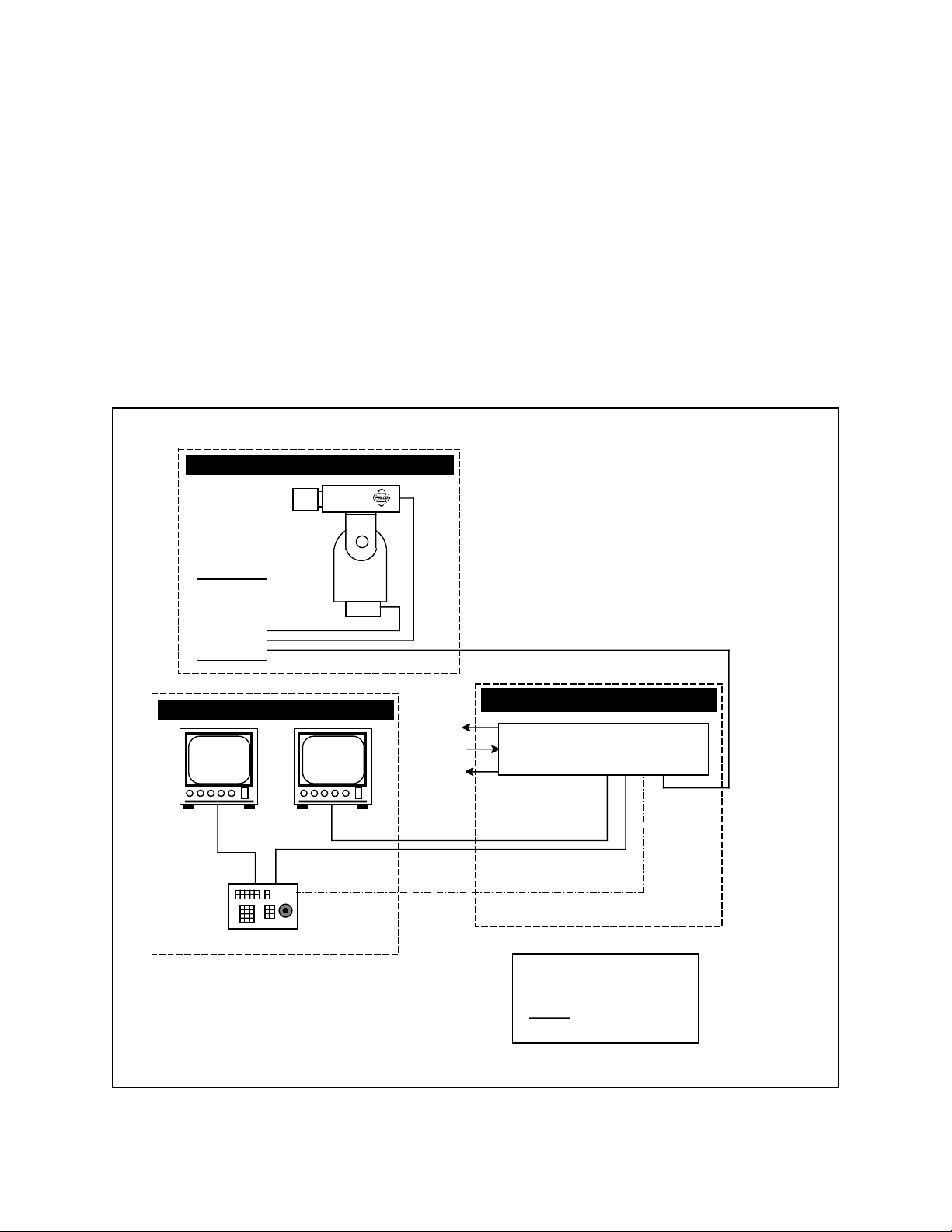
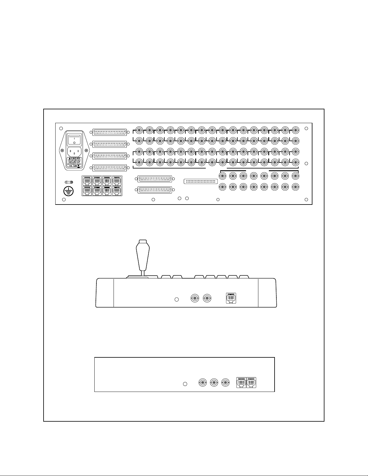
1 CM8500 Configuration Diagram.................................................................................................. 2-1
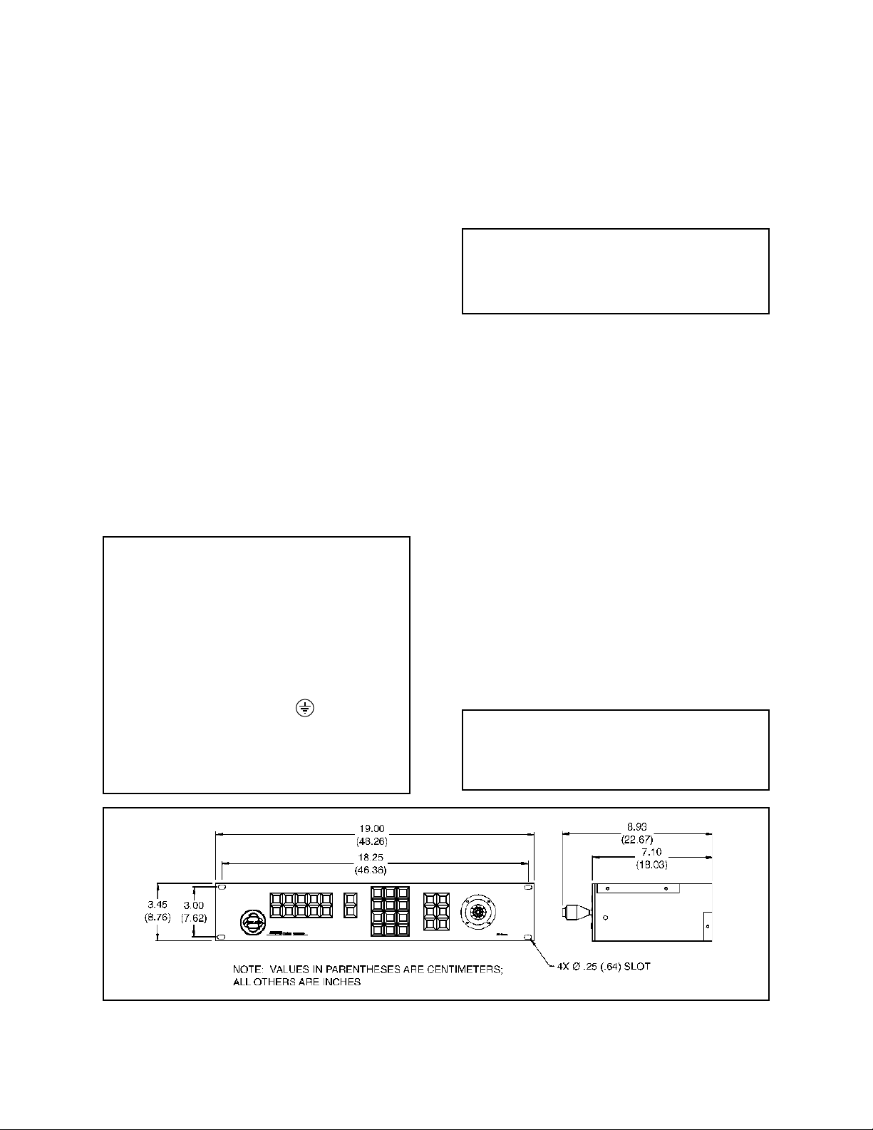
2 CM8505R Dimension Drawing.................................................................................................... 4-1
2A CM8503A-1 Card Cage and CM8505 Keyboard Back Panel Connector Layout ........................ 4-2
3 Data Cable Pin Assignments....................................................................................................... 4-3
4 Junction Box Pin Assignments .................................................................................................... 4-3
5 CM9505UPS/CM9505J Configuration ........................................................................................ 4-4
6 CM8503-1 Card Cage Top View.................................................................................................. 4-5
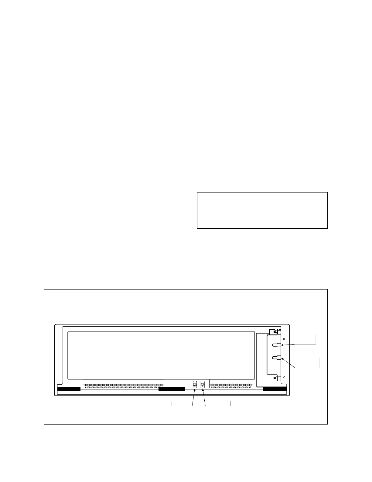
7 CM8502-1/CM8503-1 Card Cage Front View ............................................................................. 4-6
7a Slide-out Motherboard Access .................................................................................................... 4-7
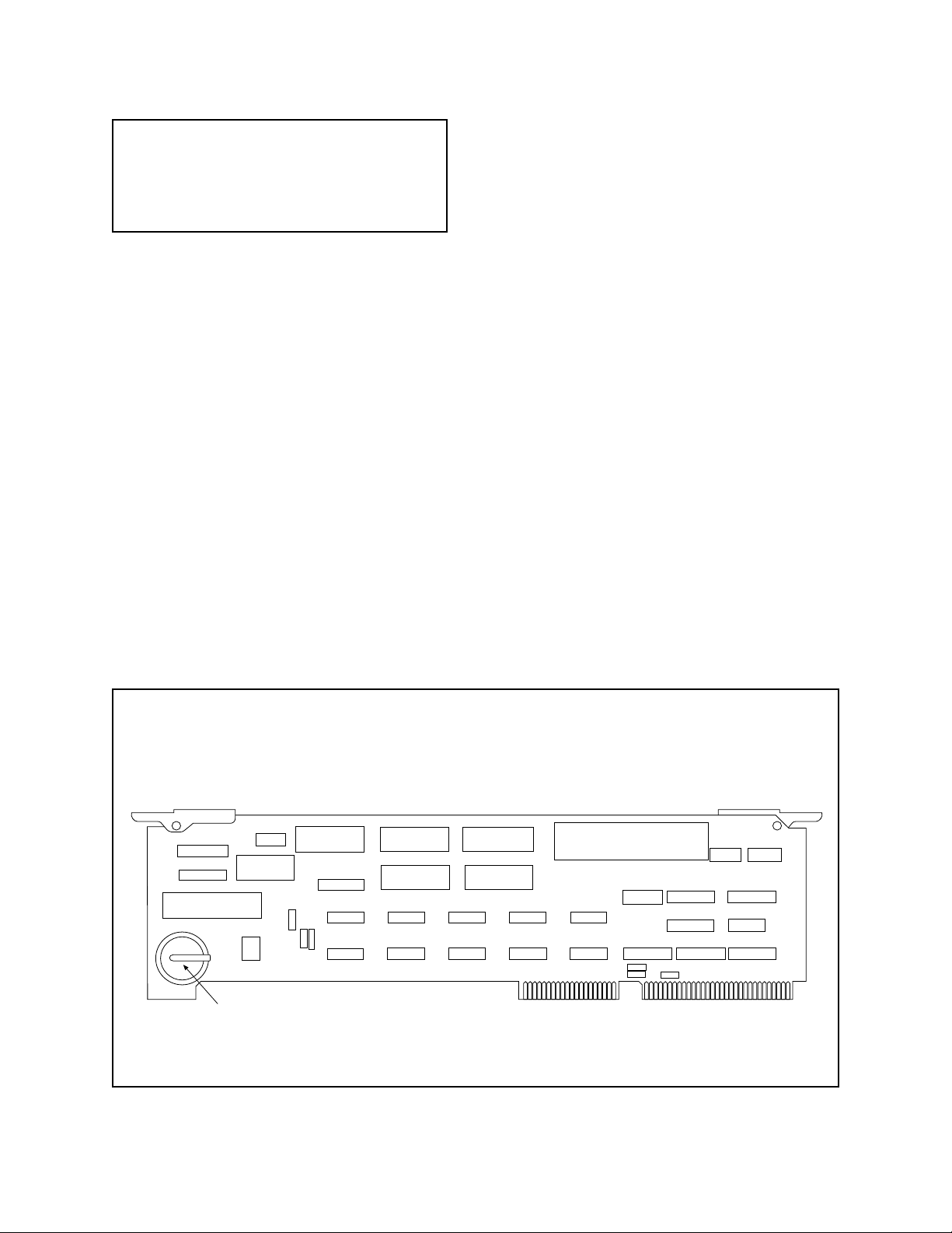
8 CPU Card Component Location.................................................................................................. 4-8
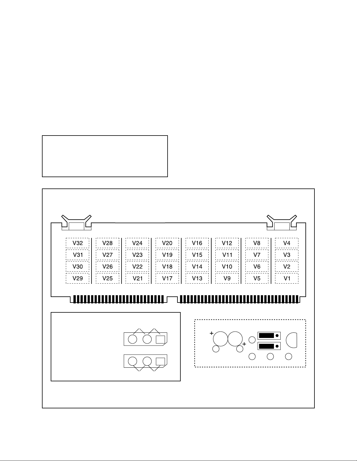
9 Buffer Card and Jumper Locations ........................................................................................... 4-10
10 Data Monitor Hookup ................................................................................................................ 4-12
11 CM8505D Keyboard/Controller................................................................................................... 5-1
12 Numeric Keypad.......................................................................................................................... 5-2
13 Selection Switches ...................................................................................................................... 5-3
14 Lens Function Switches .............................................................................................................. 5-3
15 Log On Screen with On-Screen Keyboard.................................................................................. 5-4
16 Main Menu Bar ............................................................................................................................ 5-5
17 System Menu .............................................................................................................................. 5-6
18 Cam Menu................................................................................................................................... 5-7
19 Keyboard Menu ........................................................................................................................... 5-8
20 User Menu................................................................................................................................... 5-8
21 Sequence Menu .......................................................................................................................... 5-9
22 Alarm Menu ................................................................................................................................. 5-9
23 Tour Menu ................................................................................................................................. 5-10
24 Event Menu ............................................................................................................................... 5-10
25 Logoff Menu ...............................................................................................................................5-11
26 Clock Programming Screen ...................................................................................................... 5-24
27 Label Programming Screen ...................................................................................................... 5-25
28 Receiver Types Programming Screen ...................................................................................... 5-26
29 Keyboard/Monitor Access Programming Screen ...................................................................... 5-29
30 User Profiles Programming Screen........................................................................................... 5-31
31 Camera Access Programming Screen ...................................................................................... 5-31
32 Sequence Description Screen................................................................................................... 5-33
33 Sequence Programming Screen ............................................................................................... 5-33
34 Alarm Description Screen ......................................................................................................... 5-34
35 Monitor and Camera Definition Screen ..................................................................................... 5-35
36 Relay Follow Menu.................................................................................................................... 5-36
37 Relay Follow Assignments Menu .............................................................................................. 5-36
38 Relay Control Menu .................................................................................................................. 5-37
39 Tour “Pick” List Menu ................................................................................................................ 5-37
40 Tour Menu and Camer a “Pick” List ............................................................................................ 5-38
41 Tour Control Menu..................................................................................................................... 5-38
42 Event Editor Menu..................................................................................................................... 5-39
43 Event Editor and Tour “Pick” List Menus ................................................................................... 5-40
44 Event Editor Menu..................................................................................................................... 5-40
45 Schedule Editor Menu ............................................................................................................... 5-40
46 Data Monitor................................................................................................................................ 6-1
47 Monitor Selection Menu .............................................................................................................. 6-2
48 Camera Selection Menu.............................................................................................................. 6-3
49 Sequence Menu .......................................................................................................................... 6-5
50 CM8500 Series Card Cage Exploded View Diagram.................................................................. 7-2
vi Pelco Manual C501M-B (10/97)
Page 7

1.0 WARNINGS
1.1 IMPORTANT SAFEGUARDS
Before installing your equipment, please read the following important safeguards as outlined by Underwriters Laboratories Inc.
Read Instructions
All the safety and operating instructions should be read
before the appliance is operated.
Retain Instructions
The safety and operating instructions should be retained
for future reference.
Heed Warnings
All warnings on the appliance and in the operating instructions should be followed.
Follow Instructions
All operating and use instructions should be followed.
Cleaning
Do not use liquid cleaners or aerosol cleaners. Use a
Damp Cloth for cleaning.
Attachments
Do not use attachments not recommended by Pelco as
they may cause hazards.
V entilation
Slots and openings in the cabinet are provided for ventilation and to ensure reliable operation of the CCTV
product, and to protect it from overheating. These openings must not be blocked or covered. The openings
should never be blocked by placing the CCTV product
on furniture, carpet, or similar surfaces. The CCTV
product should never be placed near or over radiators
or heat registers. This CCTV product should not be
placed in a built-in installation, such as a book case or
rack unless proper ventilation is provided or Pelco’s
installation instructions are adhered to.
Power Sources
This CCTV product should only be operated from the
type of power source indicated on the marketing label.
If you are not sure of the type of power supply to your
installation location, consult your local electrical building official or power company. Refer to the operating
instructions for appliances intended to operate from
battery or other power sources.
Grounding
This CCTV product is equipped with a 3-wire “grounding” type plug, having a third (grounding) pin. This plug
will only fit into a “grounding” type power outlet. This
is a safety feature. If you are unable to insert the plug
into the outlet, contact your electrician to replace your
obsolete outlet. Do not defeat the “grounding” type plug
since it is provided to ensure your safety.
Water and Moisture
Do not use this CCTV product near water - for example,
near a kitchen sink, wash bowl, bath tub, sprinkler, in a
wet basement or near a swimming pool, and the like
unless it is specifically marked “for use in wet locations”.
Accessories
Do not place this CCTV product on an unstable cart,
stand, tripod, bracket, or table. The CCTV product may
fall, causing serious injury to a child or adult, and serious damage to the appliance. Use only with a cart, stand,
tripod, bracket or table recommended by Pelco, or supplied by Pelco with the product. When mounting the
appliance, follow Pelco’s installation instructions, and
use only mounting accessories recommended by Pelco.
Cart & Stand
An appliance and cart combination should be moved
with care. Quick stops, excessive force, and uneven
surfaces may cause the appliance and cart combination
to overturn.
Power-Cord Protection
Power-supply cords should be routed so that they are
not likely to be walked on or pinched by items placed
upon or against them, paying particular attention to
cords at plugs, convenience receptacles, and the point
where they exit from the appliance.
Overloading
Do no overload wall outlets and extension cords as this
can result in a risk of fire or electric shock.
Object and Liquid Entry
Never push objects of any kind into this CCTV product
through openings as they may touch dangerous voltage
points or short-out parts that could result in a fire or
electric shock. Never spill liquid of any kind on the
CCTV product.
Servicing
Do not attempt to service this CCTV product yourself
as opening or removing covers may expose you to dangerous voltages or other hazards. Refer all servicing to
qualified service personnel.
Pelco Manual C501M-B (10/97) 1-1
Page 8
Damage Requiring Servicing
Unplug this CCTV product from the wall outlet and
refer servicing to qualified service personnel under the
following conditions:
a. When the power-supply cord or plug is damaged.
b. If liquid has been spilled, or objects have fallen
into the CCTV product.
c. If the CCTV product is not marked “Suitable for
Wet Locations” and it has been exposed to rain or
water.
d. If the CCTV product does not operate normally by
following the operating instructions. Adjust only
those controls that are covered by the operating
instructions as an improper adjustment of other
controls may result in damage, and will often require extensive work by a qualified technician to
restore the CCTV product to its normal operation.
e. If the CCTV product has been dropped or the cabi-
net has been damaged.
f. When the CCTV product exhibits a distinct change
in performance - this indicates a need for service.
Replacement Parts
When replacement parts are required, be sure the service technician has used replacement parts specified
by Pelco or have the same characteristics as the original part. Unauthorized substitutions may result in fire,
electric shock, or other hazards.
Safety Checks
Upon completion of any service or repairs to this CCTV
product, ask the service technician to perform safety
checks to determine that the CCTV product is in proper
operating condition.
WARNING
This product has been evaluated for INDOOR USE
ONLY unless it bears the marking FOR USE IN WET
LOCA TIONS.
W ARNING
To reduce the risk of electric shock hazard, do not remove the cover of the unit. This unit can not be serviced by the user and must be sent to a qualified service person for repair when it fails to function.
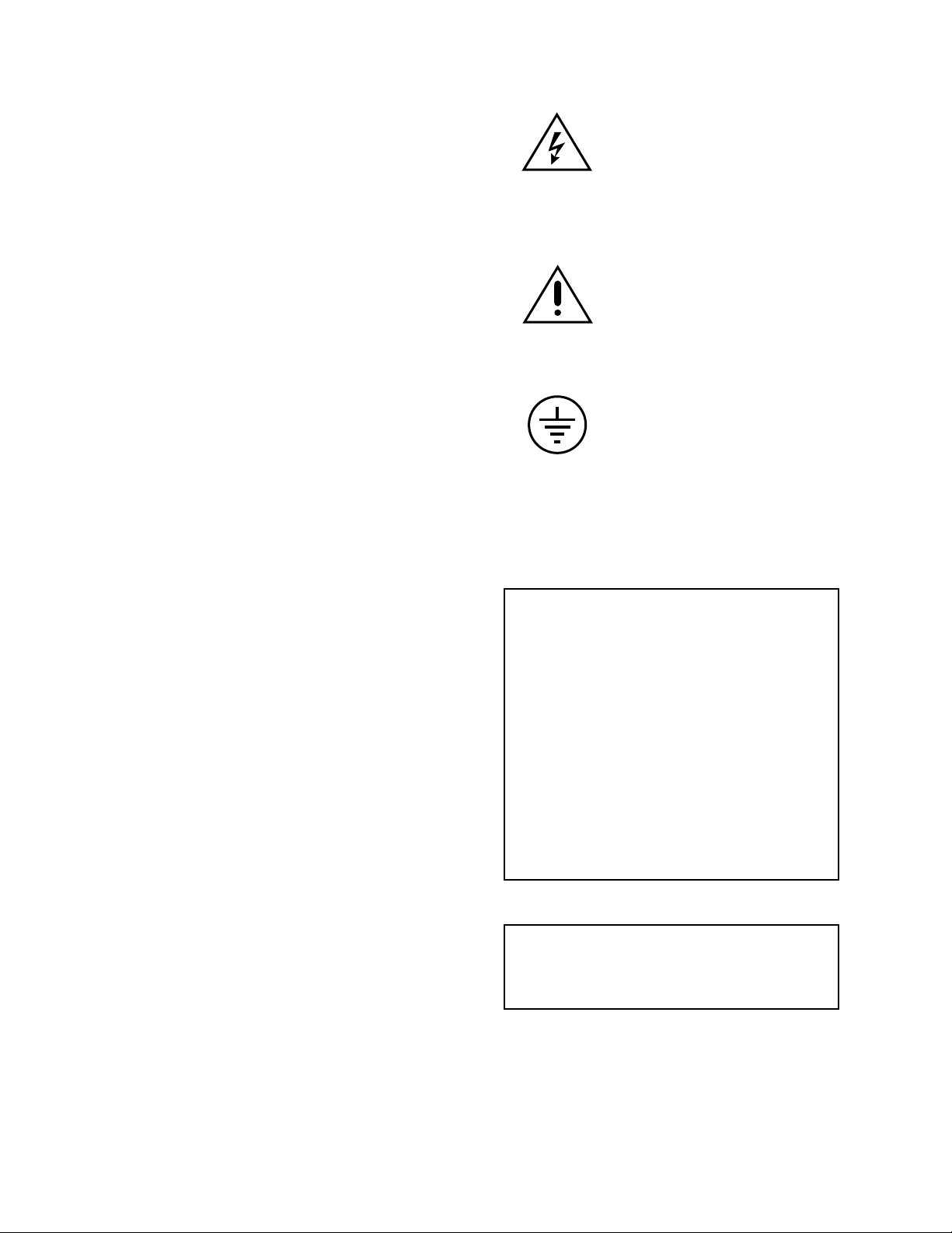
The Lightning Flash with an arrow
head symbol within an equilateral
triangle means that if the enclosure
is opened, electrical circuitry is exposed which imposes an electric
shock hazard to persons present.
The Exclamation Point within an
equilateral triangle means the operating instructions contain important
information on how to operate and
maintain the appliance.
This symbol represents an internal
protective grounding terminal. Such
a terminal must be connected to earth
ground prior to making any other
connections to the equipment.
1.2 REGULATORY NOTICES
Federal Communications Commission (FCC) Part 15
Information
NOTE: This equipment has been tested and
found to comply with the limits of a Class A
digital device, pursuant to part 15 of the FCC
rules. These limits are designed to provide reasonable protection against harmful interference
when equipment is operated in a commercial
environment. This equipment generates, uses,
and can radiate radio frequency energy and, if
not installed and used in accordance with the
instruction manual, may cause harmful interference to radio communications. Operation of
this equipment in a residential area is likely to
cause harmful interference in which case the
user will be required to correct the interference
at his own expense.
89/336/EEC EMC Directive, EN50081-1, EN55022
WARNING: This is a Class A product. In a
domestic environment this product may cause
radio interference, in which case the user may
be required to take adequate measures.
1-2 Pelco Manual C501M-B (10/97)
Page 9
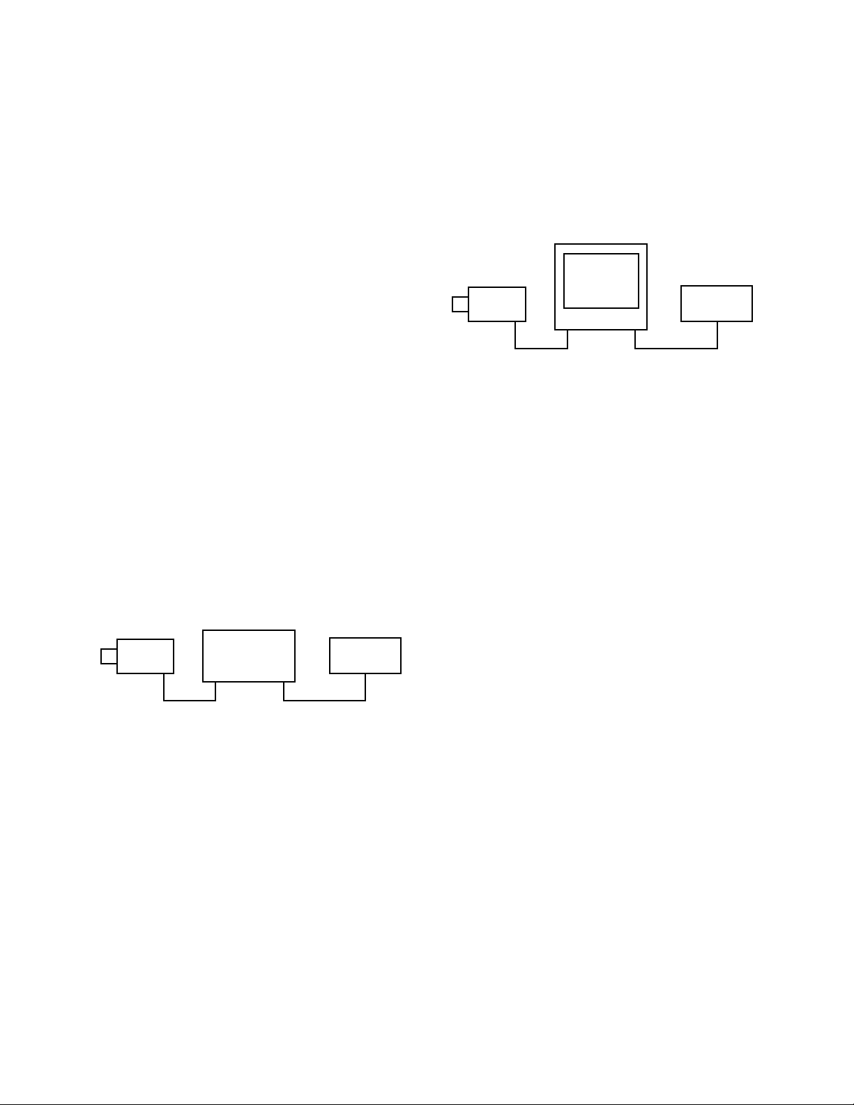
2.0 GENERAL DESCRIPTION
System 8500 is a microprocessor-based cross-point
video matrix switcher capable of handling up to 32 video
inputs to 16 monitor outputs (8 monitor outputs with
CM8502A-1), from as many as 8 independent keyboard/
controllers. It is completely compatible with all
Coaxitron® Receiver/Drivers for single coaxial control
of pan/tilts and motorized lens functions.
TYPICAL CAMERA LOCATION WITH PT&Z
VIDEO
The full-feature standard software package can be programmed by the user to custom tailor the System 8500
for each individual application. Included in the software package are system management features, password protection/priority, preset position options, tour
and event scheduling, pattern scanning and full titling
and time/date generation.
NOTE: System 8500 offers 32 PTZ control outputs. Any
number of these 32 can be Coaxitron-control, the remainder can be all Wiretron or all RS-422 depending on which
option board is being used.
RX/DR
TYPICAL CONTROL LOCATION
MON
1
DATA
MONITOR
KEYBOARD 1
PT&Z
MON
2
PELCO
32 RS422
OUTPUTS
OR
32 WIRETRON
OUTPUTS
32 ALARM
INPUTS
32 RELAY
OUTPUTS
UP TO
16
MONITORS
UP TO
8
KEYBOARDS
UP TO 32 VIDEO INPUTS
VIDEO & CONTROL DISTRIBUTION POINT
CM8500 CARD CAGE
MONITOR 2 VIDEO
OUTPUT
MONITOR 1 VIDEO OUTPUT
KEYBOARD 1 DATA/PWR LINE
8-conductor
flat phone cable
Coax Cable
Figure 1. CM8500 Configuration Diagram
Pelco Manual C501M-B (10/97) 2-1
Page 10

2.1 MODELS AND ASSOCIATED
EQUIPMENT
2.1.1 CPU/Card Cage/Power Supply
CM8502A-1 Card Cage capable of 32 inputs and
up to 8 monitor outputs. Each output requires a CM8504 I/O card.
(CM8502A-1 is shipped with one
CM8504 I/O card).
CM8502A-1-P AL CE-compliant version of CM8502A-1
CM8503A-1 Card Cage capable of 32 inputs and
up to 16 monitor outputs. Each
output requires a CM8504 I/O
card. (CM8503A-1 is shipped with
one CM8504 I/O card).
CM8503A-1-PAL CE-compliant version of CM8503A-1
2.1.2 Video Input/Output Matrix Card
CM8504 32 input by 1 output video matrix
card for I/O expansion in CM8502-1
and CM8503-1 Card Cages.
2.1.3 Keyboard Controllers
CM8505D Full-function desktop keyboard for
System 8500. Provides joystick control for pan/tilt functions, lens control
switches, auxiliary function switches,
numeric data entry keypad. Derives
power from main CPU/Card Cage.
(See section 4.3.2.3 for maximum
wire-run distance from CPU to keyboard.) Connects to CPU utilizing integral RJ-45 8-pin modular female
connector. A 25 foot interconnect
cable is included with all keyboards.
CM8505D-PAL CE-compliant version of CM8505D
CM8505R Full-function 19" EIA rack mount
keyboard.
CM9505UPS Remote power supply for CM8505
keyboards. For use when power supplied from CPU is inadequate due to
excessively long wire runs or when
CPU derived power is impractical or
impossible (i.e., fiber-optic transmission of RS-422 keyboard data). See
section 4.3.2.3 for recommended
wiring parameters.
NOTE: Future references in this manual to
the CM8502A-1, CM8503A-1, CM8505D and
CM9505UPS include the models that are CE
compliant.
CM9505UPS-X CE-compliant version of CM9505UPS
CM9505J Junction box set to adapt keyboard
RJ-45 8-pin male modular cord/
connector to multiconductor cable.
Set of two (2). Barrier strip to RJ45 8-pin female modular connector.
Also includes one pre-assembled 25
foot cable for CPU end.
CM9505IC-50 50 foot Keyboard-to-CPU extra
length cable pre-assembled with
modular RJ-45 connectors.
2-2 Pelco Manual C501M-B (10/97)
Page 11

2.1.4 Optional Feature Circuit Cards
2.1.5.1 Standard Receiver/Drivers
CM8506 Communication circuit card to allow
the CM8500 to communicate with
Wiretron Receiver/Drivers. Mounts
to Buffer Card.
CM8507 Communication circuit card to allow
the CM8500 to communicate with
Pelco RS-422 receiver/drivers (either
Spectra™, Intercept® or Legacy®).
Mounts to Buffer Card.
CM8532 32 alarm/32 relay circuit card kit to
allow for direct monitoring of 32
alarms and the use of 32 relay outputs programmable in software.
Mounts to backplane of CM8502-1/
CM8503-1.
2.1.5 Receiver/Drivers
NOTE: See Pelco specification sheet C550 for
additional information on Coaxitron® CX9000
Series Receiver/Drivers, available options and
accessories. (Also see programming instructions for additional information on configuring
the system for specific receiver/drivers.)
CX9024RX Coaxitron® outdoor receiver for 24
VAC pan/tilt units, 24 VAC camera
power, zoom lens control and auxiliary functions. (Requires 120 V AC input power.)
CX9024RX-PP Same as CX9024RX except designed
for use with preset position option for
preset capable pan/tilts and lenses.
Can store 32 preset position locations. The first eight are direct contact closure capable for call-up.
CX9024RXI Same as CX9024RX except designed
for indoor use.
CX9024RXI-12V Same as CX9024RXI except with 12
VDC camera power output.
CX9024RXI-PP Same as CX9024RX-PP except de-
signed for indoor use.
CX9115RX Coaxitron® outdoor receiver for 120
VAC pan/tilt units, 120 VAC camera
power, zoom lens control, and auxiliary functions. (Requires 120 V AC input power.)
NOTE: With Spectra™, the receiver/driver
is an integral part of the dome.
CX9115RX-PP Same as CX9024RX-PP except for
120 VAC pan/tilt and camera power
outputs.
CX9115RXI Same as CX9115RX except designed
for indoor use.
CX9115RXI-PP Same as CX9024RXI-PP except for
120 VAC pan/tilt and camera power
outputs.
CX9224RX Same as CX9024RX except for 24
VAC input power.
CX9224RX-PP Same as CX9024RX-PP except for
24 VAC input power .
CX9224RXI Same as CX9224RX except designed
for indoor use.
CX9224RXI-PP Same as CX9024RXI-PP except for
24 VAC input power .
Pelco Manual C501M-B (10/97) 2-3
Page 12

2.1.5.2 Intercept®/Legacy
Receiver/Drivers
®
DRD08 Dome receiver/driver for 8-inch In-
DRD14 Dome receiver/driver for 14-inch In-
LRD41 – Coaxitron® receiver/driver for
***
tercept® series domes. (Refer to
Specification Sheet C416 for specific
ordering information.)
***
tercept® series domes. (Refer to
Specification Sheet C454 for specific
ordering information.)
*** *
Legacy® series pan/tilts. (Refer to
Specification Sheet C277 for specific
ordering information.)
* Denotes different model numbers.
2.2 CERTIFICATIONS
The following CM8500 components are compliant with
FCC regulations, Part 15, Class A:
CM8502A-1 card cage
CM8503A-1 card cage
CM8504 video matrix card
CM9505UPS remote power supply
The following CM8500 components are compliant with
EEC regulations 89/336 EEC EMC Directive,
EN50081-1, EN55022:
CM8502A-1-PAL card cage
CM8503A-1-PAL card cage
CM8505D-PAL keyboard
CM9505UPS-X remote power supply
CM8504 video matrix card
2-4 Pelco Manual C501M-B (10/97)
Page 13

3.0 SPECIFICATIONS
3.1 CARD CAGE
3.1.1 General
Programmable switching duration: Minute, 1 second
Programmable number of steps/sequence: 32
Maximum number of sequences: 16
3.1.2 Video Inputs
Number of inputs: 32
Type: 75-ohm unbalanced terminating or looping; jumper selectable
Level: 1V peak-to-peak
Connector type: Panel-mount BNC
3.1.3 Video Outputs
Number: 1-16
Type: 75-ohm unbalanced
Level: 1V peak-to-peak nominal
Video fail detection:
Type: Vertical sync detector
Action: Switch to back up sync generator
Connector type: Panel-mount BNC
3.1.4 Video Specifications
Frequency response: ± 3 dB 20 Hz - 10 MHz
Gain: Zero dB (± 0.5 dB)
Differential gain: Typical 0.5% - Max. <1.0%
Differential phase: Typical 0.5% - Max. <1.0%
Field tilt: Typical 0.3% - Max. <0.5%
Line tilt: Typical 0.25% - Max. <0.5%
Hum: <-60 dB (below <1V p-p)
Signal to noise: > 60 dB
Cross talk (input-to-input): >-60 dB @ 10 MHz
Feedthrough (input-to-output): >60 dB @ 10 MHz
3.1.5 Character Generator
Display: White with black border
Programmable Label Descriptions: 20 Alphanumeric characters maximum
Pelco Manual C501M-B (10/97) 3-1
Page 14

3.1.6 Keyboard Interface
Protocol: Balanced differential 10V peak-to-peak
Number of ports: 8
Number of independent keyboards: 8 maximum
Baud Rate: 9600
Connector type: RJ-45 8-pin modular (female)
Cable type (supplied): 25 feet, flat, unshielded
(may be shielded)
Programmable: Y es; on-screen, menu-driven
3.1.7 Alarm Interface Inputs
Number of inputs: 32
Connector type: Two (2) 37-pin D-type female
Sensing: Normally open
3.1.8 Relay Follow Outputs
Number of outputs: 32
Connector type: Two (2) 50-pin D-type female
Contact configuration: Double pole, normally open or normally closed
Contact rating: 1A @ 24 VDC, 0.5A @ 120 VAC
3.1.9 Power Supply
Input voltage: 120/230 VAC, 50/60 Hz
Power consumption: 100 W
Ambient operating temperature range: 20° to 120°F (-7° to 49° C)
Humidity: 80% max.
Fusing: 120 VAC models: 2 A @ 250 VAC, 5 x 20 mm
230 VAC models: 1 A @ 250 VAC, 5 x 20 mm
Power on/off switch: Rocker type
3.1.10 Physical Specifications
Dimensions: 17.07"W x 5.25"H x 20.06"D
(43.36 cm x 13.34 cm x 50.95 cm)
Approximate Weight:
Fully-configured: 34 lbs (15.5 kg)
Card Cage Only: 24 lbs (11.0 kg)
Shipping Weight:
Fully-configured 37 lbs (16.8 kg)
Card Cage Only: 27 lbs (12.3 kg)
Construction: Cover - Steel, gray poly vinyl powder coat
3-2 Pelco Manual C501M-B (10/97)
Page 15

3.2 KEYBOARD
3.2.1 General
Numeric keypad: 12 keys; [0]-[9], [CLEAR], [SELECT]
Function keypad: 12 keys; [ESCAPE], [SEQ], [TOUR], [FLIP], [NEXT],
[CAM], [MON], [ALARM ACK], [RELAY TRIGGER],
[PREV],[PATTERN],[PRESET]
Lens function switch block: 6 momentary switches; [ZOOM WIDE], [ZOOM TELE],
[FOCUS NEAR], [FOCUS FAR], [IRIS CLOSE],
[IRIS OPEN]
Joystick: Vector-solving, variable-speed
3.2.2 Keyboard Electrical Specifications
Input voltage: ±12 VDC
Power consumption: 7W
Ambient operating temperature: 20° to 120°F (-7° to 49° C)
Humidity: 80% max
Connector type: RJ-45 8-pin modular (female)
3.2.3 Keyboard Communications
Protocol: Balanced differential 10V peak-to-peak
Number of ports: 1
Baud rate: 9600 baud
Connector type: RJ-45 8-pin modular (female)
3.2.4 Physical Specifications
Dimensions: 11.82"W x 4.10"H x 8.86"D
(30.02 cm x 10.41 cm x 22.50 cm)
Weight: 3 lbs 6 oz (1.6 kg)
Construction: Injection-molded plastic
Shielding: EMI and RFI shielded
Pelco Manual C501M-B (10/97) 3-3
Page 16

(This page intentionally left blank.)
3-4 Pelco Manual C501M-B (10/97)
Page 17
4.0 INSTALLATION
4.1 INSTALLATION PREPARATION
Before installing your CM8500 system, it is necessary
to know how the system will be configured. This information is needed not only for the hardware installation, but is also necessary when programming the
CM8500 system.
Section 5.5.1 contains important information and blank
forms that will assist you in preparing for the installation. Refer to this section prior to installing your
CM8500 system.
If you have the CM8505R keyboard controller, mount
it securely into a suitable equipment rack or frame, using the supplied rack mount screws and washers. Keep
in mind the visibility and accessibility of the control
functions while installing the keyboard.
4.3 SYSTEM HOOKUP
IMPORTANT NOTE: Remove the paper
between the battery contacts on the CPU card
if it has not been removed. Refer to Figure 8
and Sections 4.3.3.1.1 and 4.3.3.1.3.
4.3.1 General
4.2 MOUNTING
The CM8502A-1 and CM8503A-1 Card Cage assemblies come pre-assembled with all circuit cards installed
and tested, ready to mount in standard 19-inch EIA racking consoles. The card cage will take 5.25 inches (13.34
cm) of vertical rack space. If ordered, individual spare
circuit cards are shipped separately. See Section 4.3.3
for instructions on individual circuit card installation
and setup.
NOTE: If you are installing the card cage in
a 19-inch rack, remove the 6-32 flathead screw
from the top of the front panel. This will allow
you to remove the front panel after the card cage
is installed in the rack.
NOTE: After installing the card cage, connect the ground lug on the back panel to earth
ground. The ground lug is located on the left
side above the ground symbol .
NOTE: Make sure the fuse module on the
rear of the card cage is installed for the correct
voltage.
The System 8500 is a third-generation Coaxitron® system, and therefore only requires a single coaxial cable or
fiber* to be installed from the main card cage to each camera location. The Coaxitron® system will receive the video
signals from each individual camera and will use the same
coaxial cable to send data to the receiver/drivers located
at or near the camera sites. Fixed camera locations do
not require the receiver/driver unless the use of auxiliary
functions is desired. Camera power can be derived from
the receiver, which is normally powered by local 120
VAC. Refer to Pelco Specification Sheet C550 for details of receiver capabilities and requirements.
In addition to being a Coaxitron® system, the CM8500
also can support Pelco Wiretron receivers or Pelco Spectra™, Legacy® or Intercept® receivers that have been
configured for control via RS-422. Wiretron operation
requires the CM8506 option board; RS-422 Spectra™,
Legacy® and Intercept® receivers require the CM8507
option board.
* NOTE: Check with your fiber-optic equipment
manufacturer for specifications and type of
equipment appropriate for compatibility with
Pelco Coaxitron® transmitters and receivers.
Figure 2. CM8505R Dimension Drawing
Pelco Manual C501M-B (10/97) 4-1
Page 18
4.3.2 Keyboard to CPU Hookup
Up to eight (8) independent keyboards may be installed.
The backplane of the main card cage has eight (8) ports
that correspond to the keyboard inputs (refer to Figure
2A). If the supplied 8-conductor flat cable assembly is
used, it only requires that one end be plugged into a
port on the CPU and the other into the port on the rear
of the keyboard. (On the CM8505R keyboard, it doesn’t
matter which port you use on the keyboard. Two connectors are provided to support the daisy chaining of
keyboards, but this feature is not currently available.)
If user-supplied cabling is installed, then the CM9505J
adapter kit should be used to facilitate installation at
both the CPU and keyboard locations. (See Section
4.3.2.4 for wire-run distance specifications.)
FUSE 3AG (5X20)
250V 2A
RELAYS OUT 1-16
RELAYS OUT 17-32
ALARMS IN 1-16
ALARMS IN 17-32
1357
2468
KEYBOARDS
35791113151719212325272931
1
4 6 8 10 12 14 16 18 20 22 24 26 28 30 32
2
TWO WIRE CONTROL 1-16
TWO WIRE CONTROL 17-32
VIDEO INPUTS
EXTERNAL VIDEO IN
1357911
24681012
VIDEO OUTPUTS
REAR VIEW CM8503A-1 CARD CAGE
VIDEO
RESET
OUT
VIDEO
INPUT
DATA
PORT
13 15
14 16
REAR VIEW, CM8505D KEYBOARD
LOOPING
VIDEO
VIDEO
OUTRESET
VIDEO
OUT
INPUT PWR/COM PWR/COM
REAR VIEW, CM8505R KEYBOARD
Figure 2A. CM8503-1 Card Cage and CM8505 Keyboard Back Panel Connector Layout
4-2 Pelco Manual C501M-B (10/97)
Page 19
4.3.2.1 CM9505UPS/CM9505J
Installation
4.3.2.3 CM9505J Wire/Pin
Configuration
The CM8502A-1 and CM8503A-1 Card Cages each
offer a total of eight (8) individual keyboard communications ports. Normally one keyboard utilizes one
communications port. Communications between each
keyboard and the CPU consists of two (2) balanced
differential data pairs and ±12 VDC supply voltages
together utilizing seven conductors. The keyboards are
supplied with 25-foot (63.5 cm) pretested interconnect cables with pre-assembled RJ-45 modular 8-pin
male connectors. Within many installations, it is necessary to install system keyboards at remote sites. The
CM9505J Junction Box allows you to convert the keyboard data cable into a set of cabling that can be run
through conduit (if necessary) for significantly greater
distances by eliminating the keyboard power connections and only running the data. The CM9505UPS reintroduces keyboard power at the keyboard end of the
cabling. See Figure 5. For distances of over 2,000 feet
(609.6 m), Pelco recommends using the CM9505UPS422 power supply/data repeater at the middle of the
run of wire in addition to the CM9505UPS.
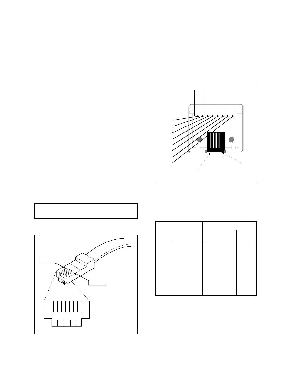
4.3.2.2 Pin Configuration
Please refer to Figure 3 for specific pinout/wiring information and make connections accordingly.
NOTE: For data connection only, do not use
connection pins 3 thru 6.
Note that the pin assignments on the CM9505J wire
connection do not match the RJ-45 modular connector.
Make connections accordingly. (The color information
printed on the CM9505J PC board has no r elevance in
this application.)
Top View
PR 3 PR 1
PR 4
1
2
3
6
7
8
5
4
Pin 8
PR 2
Pin 1
Figure 4. Junction Box Pin Assignments
The pinout configuration is as listed on the following
table. Refer to Figure 3 for more information.
CPU Keyboard
Pin# Function Function Pin#
1 Data in + Data out + 1
2 Data in - Data out - 2
Pin 1
3 -12 VDC -12 VDC 3
4 +12 VDC +12 VDC 4
5 Ground Ground 5
6 Spare Spare 6
Pin 8
7 Data out - Data in - 7
8 Data out + Data in + 8
4.3.2.4 Cable Distances
12345678
The maximum distances allowed are governed primarily by the 12 VDC supply voltages needed to power
the active components of the keyboard. The RS-422
data lines far exceed the distance restrictions of the DC
power lines.
Figure 3. Data Cable Pin Assignments
Pelco Manual C501M-B (10/97) 4-3
Page 20
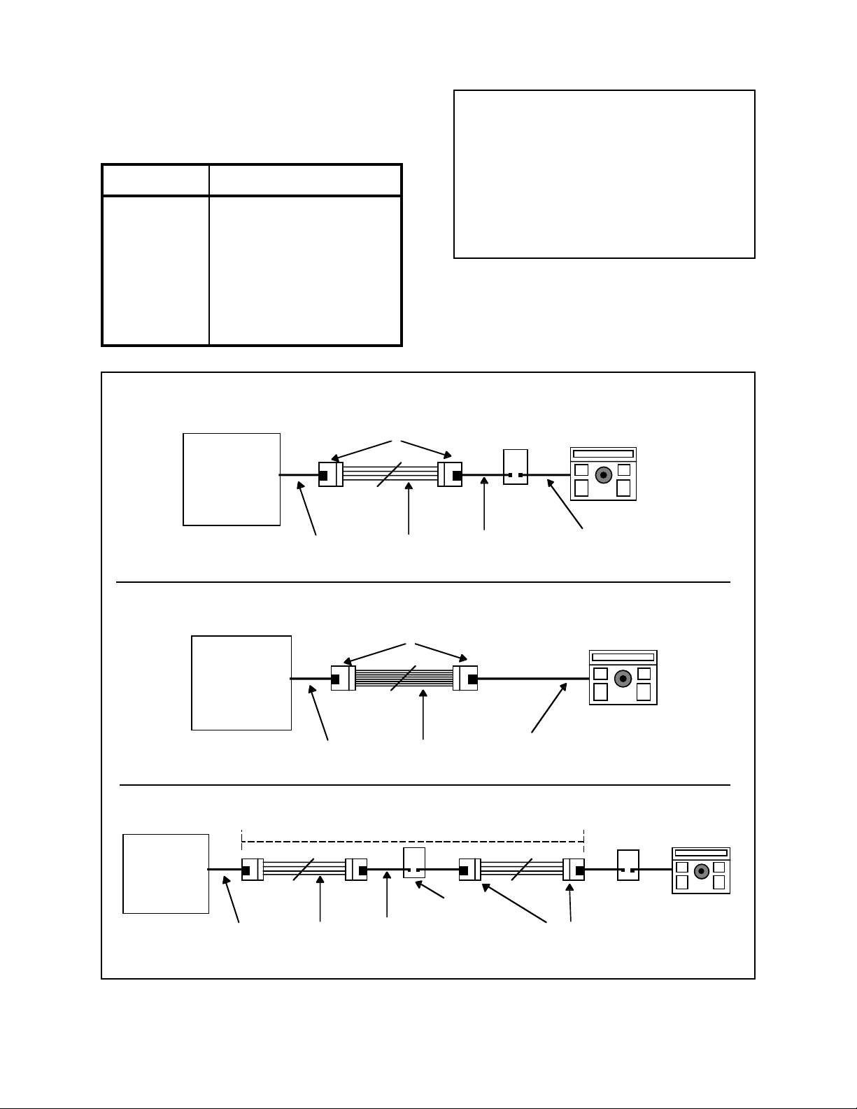
If the CPU is to supply power to the keyboards, the
distance limitations based on conductor size are shown
in the following table:
NOTE: The 8-conductor cable provided by
Pelco with the CM8505D, CM9505J or
CM9505UPS is 28 gauge.
Wire ga. ft/m
14 832 / 254
16 416 / 127
18 275 / 84
20 166 / 51
22 104 / 32
24 64 / 20
28 26 / 8
32 10 / 3
Data Configuration only with CM9505UPS
CM9505J
Junction Box
Matrix System
Card Cage
Data Cable Supplied
With Junction Box
User-Supplied
4-conductor
NOTE: When using the CM9505J with the
CM9505UPS , use pins 1, 2, 7, and 8 ONLY.
This will allow for data to be passed through,
and for power to be reintroduced at the
CM9505UPS.
Remote KeyboardCM9505UPS
Data Cable
Supplied With
UPS
Data Cable
Supplied With
Keyboard
Data and Power Configuration without CM9505UPS
Matrix System
Card Cage
Data Cable Supplied
With Junction Box
CM9505J
Junction Box
User-Supplied
8-conductor
Data Cable
Supplied With
Keyboard
Remote Keyboard
Data Configuration Only with CM9505UPS and CM9505UPS-422
Distance Greater Than 2,000 feet
Matrix System
Card Cage
CM9505UPS-422
Data Cable Supplied
With Junction Box
User-Supplied
4-conductor
Data Cable
Supplied With
UPS
CM9505J
Junction Box
Figure 5. CM9505UPS/CM9505J Configuration
CM9505UPS
4-4 Pelco Manual C501M-B (10/97)
Page 21
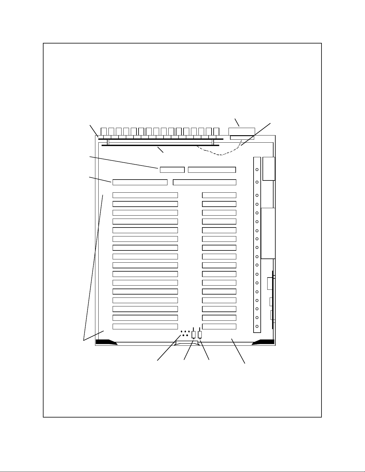
BACKPLANE
CPU
SLOT
ALARM / RELAY CONNECTORS
RIBBON
CABLES
(4)
ALARM / RELAY INTERFACE
BUFFER
CARD
SLOT
11
13
10
12
14
15
16
FAN
1
2
3
4
5
6
7
8
9
POWER
SUPPLY
VIDEO
INPUT/OUTPUT
SLOTS (1-16)
TEST
POINTS
RESET SFT CLR
MOTHER
BOARD
Figure 6. CM8503A-1 Card Cage Top View
Pelco Manual C501M-B (10/97) 4-5
Page 22
4.3.2.5 Interfacing Keyboard to CPU
Via Fiber, Modem or Microwave
The CM8500 utilizes a full duplex balanced differential communications scheme between keyboard and
CPU, similar to RS-422 except that voltage levels are
10 volts peak to peak. Call Pelco if there are any application related questions.
4.3.2.6 Keyboard Self-Test Program
LED will be illuminated. The Power On LED, when
on, indicates the unit On/Off switch is in the On position. The +5 VDC LED indicates the power supply is
operating.
Pressing the Reset button while the unit is operating
will cause the system to initialize and restart operation.
This is the same as cycling power. Pressing the SFT
CLR (Software Clear) button during normal operating
conditions does not affect operation.
This option not currently available.
4.3.3 CM8502A-1/CM8503A-1 Card
Cage Configuration
The CM8502A-1 Card Cage may be configured for one
to eight monitor outputs and the CM8503A-1 may be
configured for one to 16 monitor outputs by adding
CM8504 Input/Output Matrix Cards. Each CM8504
card allows the 8500 system to be expanded by one
monitor output. The input capacity (32 cameras) remains unchanged by the addition or deletion of CM8504
cards.
Figure 6 shows the board location for the CM8503A-1
Card Cage. The CM8502A-1 Card Cage board locations are identical, with the only difference being eight
(8) fewer video input/output slots. (Slots 9-16 are not
present in the CM8502A-1 version.) Refer to Figure 7
for the front view of the CM8502A-1/CM8503A-1 Card
Cages. When the power switch is in the On position,
both the green Power On LED and the red +5 VDC
The following procedure will erase all user-programmed
memory:
1. Hold in the RESET and SFT CLR buttons for five
seconds.
2. Release the RESET button.
3. Release the SFT CLR button.
CAUTION: Cycling power with the SFT
CLR button pushed will erase all userprogrammed memory. (Pressing the RESET button is the same as cycling power .)
+5 VDC
LED
VIDEO INPUT/OUTPUT MATRIX CARDS
RESET SFT CLR
PWR ON
LED
Figure 7. CM8502A-1/CM8503A-1 Card Cage Front View
4-6 Pelco Manual C501M-B (10/97)
Page 23
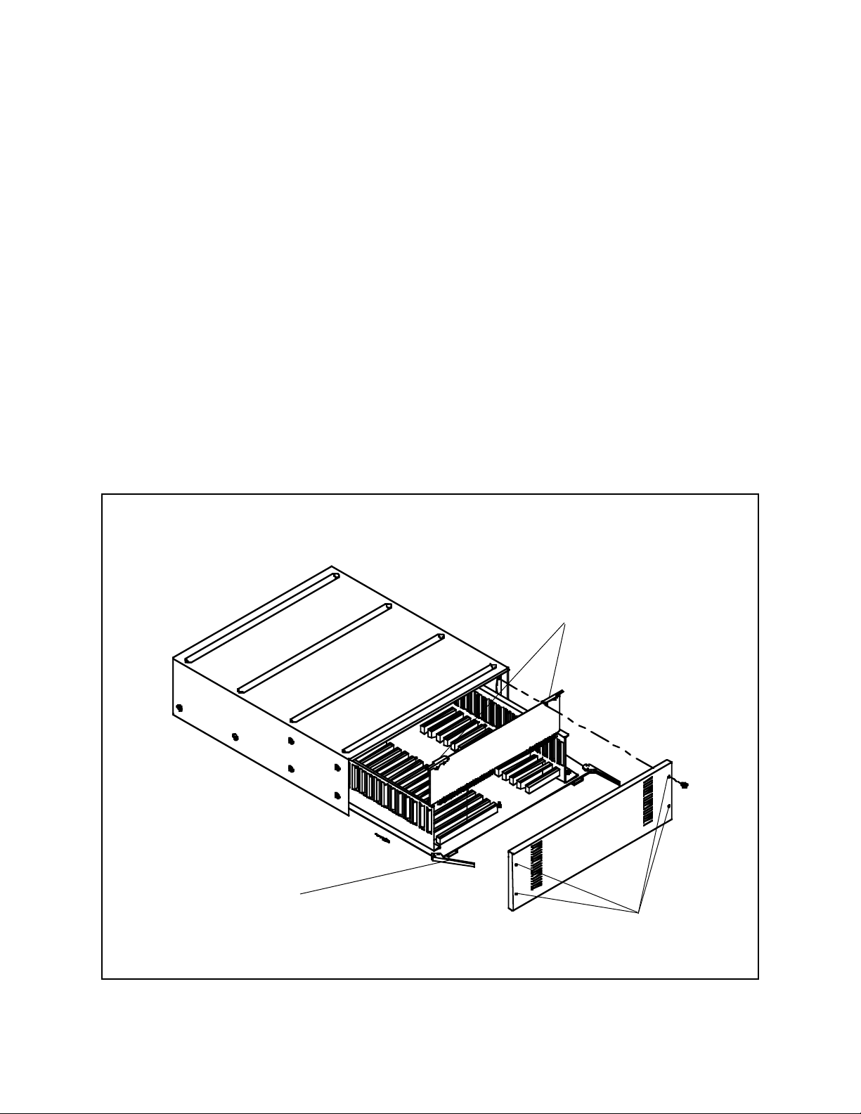
4.3.3.1 Removal/ Replacement of
Individual Circuit Cards
4.3.3.1.1 Motherboard Access
3. To remove an individual circuit board, pull up on
the metal ejector tabs. The card should easily slide
out of the card slots of the motherboard.
The CM8500 card cage has been designed with userconvenience and operational integrity foremost in mind.
The slide-out motherboard makes dependable electrical contact while providing an easy-to-service system
for circuit board upgrade and replacement.
To upgrade and/or replace circuit boards, perform the
following steps:
1. Remove the four (4) front cover screws from the
corners of the CM8500 card cage front panel and
remove the front panel.
2. Use the two (2) motherboard PCB ejectors to pull
and slide the main motherboard out of the card
cage.
4. T o install an individual circuit board on the mother board, gently press the contact edge of the circuit
board into the appropriate card slots on the motherboard. Make sure the metal ejector tabs lay down
flat against the circuit board before sliding the
motherboard back into the card cage.
5. After all boards have been replaced/added, slide
the motherboard back into the card cage unit and
lock the ejectors back into place.
6. Replace the front cover and reattach the four (4)
grey screws that were removed in Step 1.
Motherboard PCB
ejector tabs
Individual PCB
ejector tabs
Front panel
mounting screws
Figure 7a. Slide-out Motherboard Access
Pelco Manual C501M-B (10/97) 4-7
Page 24
WARNING: To reduce the risk of personal
injury due to electrical shock and also to prevent possible damage to the electronic circuitry ,
always remove power to the unit prior to removing or installing any printed circuit boards.
4.3.3.1.2 Insertion/Extraction of
the CM8504 I/O Card
Insert the CM8504 Input/Output card into the appropriate slot in the motherboard by grasping the white
handles, aligning the card with the card guides and pushing down firmly until the card seats in the edge connector. To remove the card, lift up the ejector handles.
4.3.3.1.3 Insertion/Extraction of
the CPU Card
The CPU Card occupies the first slot (slot closest to the
backplane) in the motherboard. T o install the CPU Card,
align the edge connector with the sockets and card
guides and press firmly into place. T o remove the card,
lift up the ejector handles.
4.3.3.1.4 Insertion/Extraction of
the Buffer Card
The Buffer Card occupies the second slot (from the
backplane) on the motherboard. To install the Buffer
Card, align the card with the socket and card guides
and press firmly into place. T o remove the card, lift up
the ejector handles.
Battery
Figure 8. CPU Card Component Location
4-8 Pelco Manual C501M-B (10/97)
Page 25

4.3.3.1.5 Installing Option Boards
The CM8500 is factory-equipped as a Coaxitron compatible only system (unless requested differently). The
CM8500 is also capable of transmitting two-wire control information in RS-422 or Wiretron formats. To
make use of the system’s two-wire capabilities, the appropriate Pelco CM8500 Option Board must be
installed to the system buffer board.
CM8506 CM8500 Wiretron compatible option
board
CM8507 CM8500 RS-422 compatible option
board
Both option boards install into the CM8500 system
using the same procedures. It is important to note that
only one option board can be installed, making the system either Coaxitron®/Wiretron compatible or
Coaxitron®/RS-422 compatible. The system cannot
work with all three information formats at the same
time.
NOTE: The CM8506/CM8507 option boards
are transmit-only units. Only the appropriate
control signals are generated from the option
boards.
4.3.3.1.6 Option Board Receiver
Connections
When working with CM8500 optional data formats,
keep the following in mind when making the two-wire
connections to the receivers.
The CM8500 system offers no receiver addressability.
Home runs are required for each receiver in the system, and each receiver (if addressability applies to the
receiver) must be set to address 1.
The following two-wire connections
must be made:
When using the CM8506 Wiretron compatible option board, the “+” output for the camera that is to be
controlled with a Wiretron receiver must be connected
to the “high” input on the Wiretron receiver. The “-”
output is to be connected to the “low” input on the
Wiretron receiver.
With the CM8507 RS-422 compatible option board,
the “+” output for the camera that is to be controlled
with an Intercept® or Legacy® receiver is to be connected to the “RX+” input on the Legacy® or Intercept® receiver. The “-” output is to be connected to
the “RX-” input on the Legacy® or Intercept® receiver .
Option Board Physical Installation
The option boards are easy to install and should take
only a minimum of time. After turning off system power
and removing the buffer board (see section 4.3.3.1.4),
notice on the un-populated side of the buffer board there
are three (3) plug-in connectors and five (5) hex
spacers. The populated side of the option board (either the CM8506 or CM8507) has the matching male
pin connections and five mounting holes.
Line the female plug-in connectors and standoffs on
the buffer board with the male pin connectors and
mounting holes on the option board. Gently press the
boards together making the plug in connections. Use
the five (5) supplied mounting screws to firmly secure
the option board to the buffer board.
Make the appropriate jumper settings on the buffer
board (each receiver that is compatible with the new
option board must have jumpers set on the buffer board
appropriately). Reinstall the new buffer board/option
board assembly into the CM8500 card cage. See section 4.3.3.2 for jumper setting information.
Again, make sure all addressable receivers are set to
address 1.
IMPORTANT: After the Option Board has
been installed, and the individual jumper selections have been made for each receiver, you
must program the system software to match
the individual receiver data formats. Refer to
Section 5.5.2.4 for Receiver T ypes Pr ogramming Screen information.
Pelco Manual C501M-B (10/97) 4-9
Page 26
4.3.3.2 Setting Termination on
Video Inputs
4.3.3.3 Determining and Setting
Monitor Output Assignments
The termination settings for the 32 video inputs are individually assigned on the Buffer Card. There are 64
jumpers located on the component side of the board,
two jumpers for each video input (designated V1
through V32). Refer to Figure 9. The board will have
to be removed from the motherboard in order to change
the setting(s). Follow the instructions for board removal
and replacement in Section 4.3.3.1.4 and refer to Figure 9 when setting the jumpers. For more information,
refer to Section 4.3.3.4.2.
NOTE: Jumper positions 1 and 2 apply to the
terminating/looping status of the individual
video inputs. Jumper positions 3 and 4 apply to
the Coaxitron®/two-wire compatibility of the
individual receiver.
Monitor output numbers automatically correspond
to the slot that the Input/Output board is installed.
The first monitor slot is the one just forward of the
Buffer Card slot. The last monitor slot is located in
the forward-most position. No other settings are
necessary.
4.3.3.4 Camera Location to Video
Input Hookup
Since the CM8500 is a Coaxitron® system, each camera input that has a Coaxitron® receiver requires only a
single coaxial cable (or fiber) to transmit both video
and camera control signals. Follow camera manufacturers’ recommendations for maximum allowable distances for their equipment.
SECTION 100
JUMPER SETTINGS
12
1 - TERMINATING
2 - LOOPING
3 - COAXITRON
4 - 2-WIRE
34
TYPICAL FOR V1 THROUGH V32
Figure 9. Buffer Card and Jumper Locations
4-10 Pelco Manual C501M-B (10/97)
Page 27
4.3.3.4.1 Cable Selection
Coaxitron requires a high quality solid copper core coaxial cable with at least 95-percent copper braid shield.
Copper-clad steel center conductor is not recommended,
nor is aluminum shield. Such construction is generally
recognized as not being adequate for baseband CCTV
systems. This type of cabling is meant for RF MATV/
CATV type systems only.
4.3.3.4.2 Termination
If there is any equipment, such as a spot monitor, between the video input of the CM8500 and the video
output from your camera or receiver/driver, make sure
that these devices are set for looping, or high impedance. Terminate the video input to the CM8500. Here,
the CM8500 is the last piece of equipment.
Camera Monitor CM8500
Coaxitron is sensitive to improper termination and care
must be taken to ensure proper installation. When a
video output from a camera or receiver/driver goes directly to a video input of the CM8500, the video input
must be terminated with 75 ohms. However , if there is
more than one piece of equipment in the video path,
only the last piece of equipment is terminated. Terminating more than one piece of equipment (double termination) causes loss of signal.
For example, if a video input to the CM8500 is going
to be looped out to the input of another device, place
the jumper on the buffer card in the CM8500 in the
looping position and terminate the input of the device
receiving its signal from the CM8500. In this case the
CM8500 is between the video source and the final piece
of video input equipment.
Other
Camera CM8500 Video Equip.
Video
Video In
In Out
Video In
In Out
Looping 75-ohm
Input termination
Video devices placed between the CPU and receiver/
driver must be passively looping and not use an amplified looping scheme. Some quad devices and VCRs use
this scheme. The amplified devices are not bidirectional
and therefore do not pass the Coaxitron® control signals. Should these devices need to be installed they must
utilize video that has first looped through the matrix
inputs .
See Section 4.3.3.2 for setting the termination jumpers.
Looping 75-ohm
Input termination
Pelco Manual C501M-B (10/97) 4-11
Page 28
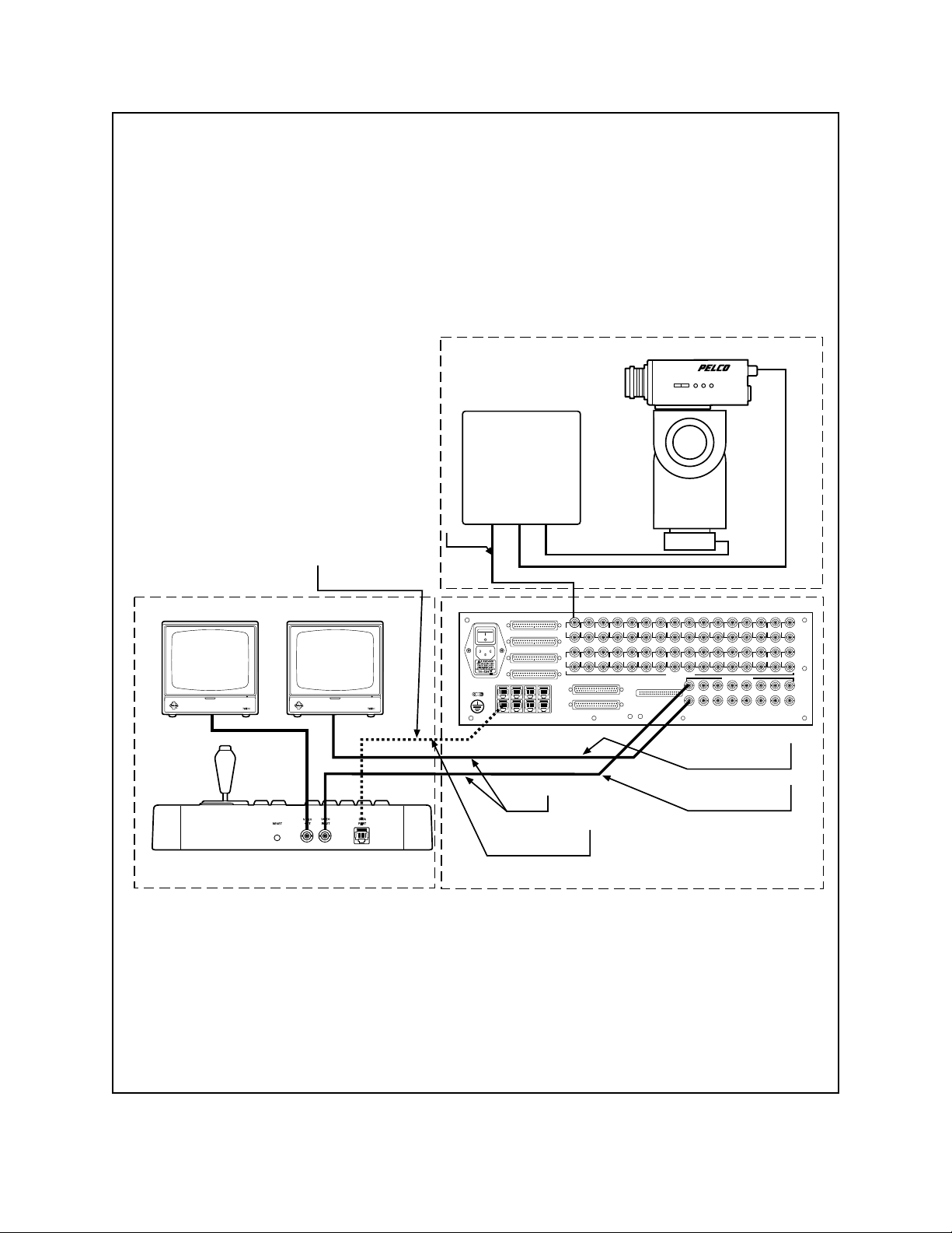
In this example, monitor 1 is “Data
Monitor,” but its use is not restricted to
programming functions. It can also be
utilized like any other system monitor and
has the additional capabilities of the “Data
Monitor.”
TYPICAL CAMERA LOCATION WITH PT&Z
RX/DR
VIDEO
2 TW PR &
3 CONDUCTOR
TYPICAL CONTROL LOCATION
MON 1
DATA
MONITOR
MON
2
KEYBOARD 1
COAX
FUSE 3AG (5X20)
250V 2A
KEYBOARD 1
DATA/PWR LINE
PT&Z
RELAYS OUT 1-16
RELAYS OUT 17-32
ALARMS IN 1-16
ALARMS IN 17-32
1357
2468
KEYBOARDS
35791113151719212325272931
1
4 6 8 10 12 14 16 18 20 22 24 26 28 30 32
2
TWO WIRE CONTROL 1-16
TWO WIRE CONTROL 17-32
EXTERNAL VIDEO IN
VIDEO INPUTS
1357911
24681012
VIDEO OUTPUTS
MONITOR 1
VIDEO OUTPUT
MONITOR 2
COAX
VIDEO OUTPUT
VIDEO & CONTROL DISTRIBUTION POINT
13 15
14 16
Figure 10. Data Monitor Hookup
4-12 Pelco Manual C501M-B (10/97)
Page 29

4.3.3.4.3 Ground Loops
One other precaution to take prior to final connections
being made is to check all input coaxial cables for the
presence of possible ground loop voltages. Sync, video,
control functions, and/or system electronics may be adversely affected by a ground loop condition. Call Pelco
if unable to correct any ground loop problems. Do not
connect cables to input connectors if ground loop voltages are present between CPU and camera sites or between camera sites through the CPU. Pelco manufactures the GIT100, ground isolation transformer, to help
alleviate ground loop problems in Coaxitron®-based
equipment. The use of fiber optics is also another means
to eliminate ground loops in a system.
4.3.3.4.4 Hookup
After ensuring that the above conditions have been met
and that all precautions have been observed, the coaxial inputs from the camera locations can be connected
to the input connectors on the backplane of the card
cage.
Be sure that each connection is secure and that the connectors are properly installed.
It is always good installation practice to mark or number all cabling. If system troubleshooting is necessary
and cables need to be disconnected, system downtime
can be minimized with a well organized cable identification system.
4.3.6 Installation/Connection of
CM8532 Alarm/Relay Interface
4.3.6.1 Alarm/Relay Interface Kit
Installation
The Alarm/Relay Interface Kit contains the Alarm/
Relay Interface Board (with ribbon cables attached)
and all hardware needed to secure the board and connectors. The Alarm/Relay Interface Board mounts
onto the Backplane of the CM8502-1 or CM8503-1
Card Cage (refer to Figure 6).
NOTE: To install the board, the top cover as
well as the CPU and buffer boards need to be
removed.
Connect the 10-pin connector from the Alarm/Relay
Interface board to the backplane of the matrix card cage.
Note that the connector is keyed and that the edges of
the connectors should match (i.e., that the connector
has not shifted over one way or the other).
Once connected, secure the Alarm/Relay Interface
Board to the standoffs with the hardware provided. Once
secured, remove the blank-off plate covering the connector slots and mount the alarm and relay interconnect ribbon cable connectors to the card cage. Refer to
the following information for the proper location of each
connector.
Alarm/Relay Interface Board Card Cage
4.3.4 Connecting Keyboard to
the Data Monitor
Each keyboard will utilize a system monitor output for
programming and keyboard feedback. Select one monitor output at the keyboard location to be the data monitor
and connect that output from the card cage to the keyboard video input connector. Connect the monitor output
from the keyboard to the appropriate monitor and ensure
correct termination (75 Ohm). Refer to Figure 10.
4.3.5 Connecting Other System
Monitors
All other system monitors may be interconnected to
the video output BNC terminal(s) of the card cage with
the appropriate length and type of coaxial cable or
fiber-optic interface equipment. The video output of
the CM8500 is a standard NTSC 1V p-p video signal.
Again, ensure for proper 75-Ohm termination at the
monitor(s) or other video processing equipment.
Pelco Manual C501M-B (10/97) 4-13
4.3.7 Alarm Input Connection
To connect alarm inputs to the system requires that the
alarm inputs first be wired into a 37-pin D-type connector (supplied by Pelco). Refer to Section 4.3.7.1
for the connector pin designations. Once wired, connect the connector to the appropriate location on the
back panel of the card cage.
P1 Relays Out 1-16
P2 Relays Out 17-32
P3 Alarms In 17-32
P4 Alarms In 1-16
Page 30

4.3.7.1 Alarm Interface 37-Pin Sub
“D” Connectors
The pin-out number assignments and configurations
shown below match the 37-pin ribbon cables used in
the alarm/relay interface.
Connector: Alarms In 1 - 16
Alarm No: Pin No:
1 In 1
1 Com 20
2 In 2
2 Com 21
3 In 3
3 Com 22
4 In 4
4 Com 23
5 In 5
5 Com 24
6 In 6
6 Com 25
37-Pin sub “D” connector (sockets).
Facing back of card cage.
Connector: Alarms In 17 - 32
Alarm No: Pin No:
17 In 1
17 Com 20
18 In 2
18 Com 21
19 In 3
19 Com 22
20 In 4
20 Com 23
21 In 5
21 Com 24
22 In 6
22 Com 25
7 In 7
7 Com 26
8 In 8
8 Com 27
9 In 9
9 Com 28
10 In 10
10 Com 29
11 In 11
11 Com 30
12 In 12
12 Com 31
13 In 13
13 Com 32
14 In 14
14 Com 33
15 In 15
15 Com 34
16 In 16
16 Com 35
23 In 7
23 Com 26
24 In 8
24 Com 27
25 In 9
25 Com 28
26 In 10
26 Com 29
27 In 11
27 Com 30
28 In 12
28 Com 31
29 In 13
29 Com 32
30 In 14
30 Com 33
31 In 15
31 Com 34
32 In 16
32 Com 35
4-14 Pelco Manual C501M-B (10/97)
Page 31

4.3.8 Relay Output Connection
4.3.8.1 Relay Interface Connector Pin
Assignments
The pin-out number assignments and configurations
shown below match the 50-pin ribbon cables used in
the alarm/relay interface.
IMPORTANT: Please note that the pin
assignments on the 50-pin connector are not
standard.
50-Pin sub “D” connector (sockets)
Facing back of card cage.
Connector: Relays Out 1-16
Relay No: Pin No:
1 NC 1
1 NO 2
1 Com 3
2 NC 4
2 NO 5
2 Com 6
3 NC 7
3 NO 8
3 Com 9
4 NC 10
4 NO 11
4 Com 12
5 NC 13
5 NO 14
5 Com 15
6 NC 16
6 NO 17
6 Com 18
7 NC 19
7 NO 20
7 Com 21
8 NC 22
8 NO 23
8 Com 24
Relay No: Pin No:
9 NC 25
9 NO 26
9 Com 27
10 NC 28
10 NO 29
10 Com 30
11 NC 31
11 NO 32
11 Com 33
12 NC 34
12 NO 35
12 Com 36
13 NC 37
13 NO 38
13 Com 39
14 NC 40
14 NO 41
14 Com 42
15 NC 43
15 NO 44
15 Com 45
16 NC 46
16 NO 47
16 Com 48
Ground 49, 50
Connector: Relays Out 17-32
Relay No: Pin No:
17 NC 1
17 NO 2
17 Com 3
18 NC 4
18 NO 5
18 Com 6
19 NC 7
19 NO 8
19 Com 9
20 NC 10
20 NO 11
20 Com 12
21 NC 13
21 NO 14
21 Com 15
22 NC 16
22 NO 17
22 Com 18
23 NC 19
23 NO 20
23 Com 21
24 NC 22
24 NO 23
24 Com 24
Relay No: Pin No:
25 NC 25
25 NO 26
25 Com 27
26 NC 28
26 NO 29
26 Com 30
27 NC 31
27 NO 32
27 Com 33
28 NC 34
28 NO 35
28 Com 36
29 NC 37
29 NO 38
29 Com 39
30 NC 40
30 NO 41
30 Com 42
31 NC 43
31 NO 44
31 Com 45
32 NC 46
32 NO 47
32 Com 48
Ground 49, 50
Pelco Manual C501M-B (10/97) 4-15
Page 32

4.3.9 2-wire control Output “D”
Connector
37-Pin sub “D” connector (sockets).
Facing back of card cage.
Output No: Connector No: Pin No:
1+ 2-Wire Control 1-16 1
1- 2-Wire Control 1-16 2
2+ 2-Wire Control 1-16 3
2- 2-Wire Control 1-16 4
3+ 2-Wire Control 1-16 5
3- 2-Wire Control 1-16 6
4+ 2-Wire Control 1-16 7
4- 2-Wire Control 1-16 8
5+ 2-Wire Control 1-16 9
5- 2-Wire Control 1-16 10
6+ 2-Wire Control 1-16 11
6- 2-Wire Control 1-16 12
7+ 2-Wire Control 1-16 13
7- 2-Wire Control 1-16 14
8+ 2-Wire Control 1-16 15
8- 2-Wire Control 1-16 16
9+ 2-Wire Control 1-16 20
9- 2-Wire Control 1-16 21
10+ 2-Wire Control 1-16 22
10- 2-Wire Control 1-16 23
Output No: Connector No: Pin No:
17+ 2-Wire Control 17-32 1
17- 2-Wire Control 17-32 2
18+ 2-Wire Control 17-32 3
18- 2-Wire Control 17-32 4
19+ 2-Wire Control 17-32 5
19- 2-Wire Control 17-32 6
20+ 2-Wire Control 17-32 7
20- 2-Wire Control 17-32 8
21+ 2-Wire Control 17-32 9
21- 2-Wire Control 17-32 10
22+ 2-Wire Control 17-32 11
22- 2-Wire Control 17-32 12
23+ 2-Wire Control 17-32 13
23- 2-Wire Control 17-32 14
24+ 2-Wire Control 17-32 15
24- 2-Wire Control 17-32 16
25+ 2-Wire Control 17-32 20
25- 2-Wire Control 17-32 21
26+ 2-Wire Control 17-32 22
26- 2-Wire Control 17-32 23
11+ 2-Wire Control 1-16 24
11- 2-Wire Control 1-16 25
12+ 2-Wire Control 1-16 26
12- 2-Wire Control 1-16 27
13+ 2-Wire Control 1-16 28
13- 2-Wire Control 1-16 29
14+ 2-Wire Control 1-16 30
14- 2-Wire Control 1-16 31
15+ 2-Wire Control 1-16 32
15- 2-Wire Control 1-16 33
16+ 2-Wire Control 1-16 34
16- 2-Wire Control 1-16 35
Ground 2-Wire Control 1-16 17, 18,
19, 36,
37
27+ 2-Wire Control 17-32 24
27- 2-Wire Control 17-32 25
28+ 2-Wire Control 17-32 26
28- 2-Wire Control 17-32 27
29+ 2-Wire Control 17-32 28
29- 2-Wire Control 17-32 29
30+ 2-Wire Control 17-32 30
30- 2-Wire Control 17-32 31
31+ 2-Wire Control 17-32 32
31- 2-Wire Control 17-32 33
32+ 2-Wire Control 17-32 34
32- 2-Wire Control 17-32 35
Ground 2-Wire Control 17-32 17, 18,
19, 36,
37
4-16 Pelco Manual C501M-B (10/97)
Page 33

5.0 PROGRAMMING THE CM85OO
5.1 THE KEYBOARD/CONTROLLER
All programming for the CM8500 is done from the system keyboard(s). Since the CM8500 is a password accessed system, any keyboard in the system may be used
for programming. Program information is entered directly
from the keyboard with the use of menus accessed and
“pulled down” on the data monitor . The data monitor is
the monitor connected to the system via the keyboard.
Accessibility to these menus also is based on user password and priority tables. A very structured, secure, and
flexible system management scheme is made possible
through the use of these programs. All operational parameters are controlled by user-programmable system
software.
• Camera video and control
• Monitor accessibility
• Video switching
• Alarm interface functions
• Tour functions
• Daily event scheduling
• PTZ preset and pattern functions, and
• Auxiliary functions
are some of the CM8500 System operations that are
programmable.
5.1.1 General
The CM8505 Series keyboard is the primary input device for programming and operating the System 8500.
All keyboards are full-function keyboards. The CM8505D
Desktop keyboard/controller is illustrated in Figure 11.
5.1.2 Joystick
The joystick serves two purposes; A. T o control the movement of a selected pan and tilt or scanning device in the
operating (run) mode, and B. To control cursor movement in the programming (edit) mode of operation. Its
operation is much like a “mouse”. The movement of the
stick “steers” the cursor, and the push button on the top
of the stick is used to “point” or “select” your choice.
The joystick control on all CM8505 model keyboards is
of the proportional type that allows for vector solving
control of all Pelco Spectra™, Intercept® and Legacy
variable speed pan and tilt devices. The farther the stick
is deflected from center, the faster the pan and/or tilt will
move. With the button depressed a “turbo” mode is
achieved, allowing the pan and tilt to move at its greatest
rate of speed in pan.
®
Please read the following programming sections closely
prior to system initialization and be sure you understand each section. If, for any reason, there are any questions regarding programming or operation please call
Pelco at (800)289-9100 or FAX us toll-free at (800)289-
9150.
Standard single-speed devices are compatible with the
controller as well. When controlling fixed speed devices, only the direction of joystick movement (not the
magnitude of movement), affects the operation of the
pan/tilt device. See the corresponding Product Specification Sheets for individual specifications.
Figure 11. CM8505D Keyboard/Controller
Pelco Manual C501M-B (10/97) 5-1
Page 34

5.1.3 Numeric Keypad
5.1.4 Selection Keys
The numeric keypad serves as the primary input device for numeric entries. Numeric entries include programming functions, call up of cameras, monitors,
presets, sequence programs, etc. In addition to numeric entries, “CLEAR” and “ENTER” functions
are accomplished by the 2 special keys. Refer to Figure 12.
There are ten digit keys [0-9] plus the [CLEAR] key
and [ENTER] key.
A brief description of the keys is as follows:
[0-9] These keys are used when selecting
items such as cameras and monitors.
Enter the desired digits first followed
by the desired function.
[CLEAR] This key will clear all programming
menus from the screen and place the
monitor back into the “run” mode.
[ENTER] This key is used to enter data, access
the Main Menu Bar when in “run”
mode and to call up the Logon screen
when the Logon prompt is present.
These 12 keys located at the top of the keyboard are
used initiate system functions.
The functions requiring numeric keypad entry are camera [CAM] and monitor [MON] call up, preset call
up [PRESET], pattern call up, [PATTERN], se-
quence enable [SEQ], tour enable [TOUR], relay enable [RELAY TRIGGER], and alarm acknowledge
[ALARM ACK]. When using these functions, enter
the numeric entry first, followed by the desired function. Pressing these keys without first entering a numeric input will bring up an on-screen table with the
available selections. The functions that require only a
single key press are escape [ESCAPE], flip function
[FLIP], next function [NEXT], and previous func-
tion [PREV].
A brief description of each function key is as follows:
[ESCAPE] This function key is not currently
used.
[CAM] This key is used to access a specific
camera. Pressing this key without
first entering a numeric input will call
up a list of all 32 camera inputs.
1 2
4
5
7 8
CLEAR
Figure 12. Numeric Keypad
0
3
6
9
ENTER
[SEQ] This key is used to access a defined
camera sequence. Pressing this key
without first entering a numeric input will call up a list of available sequences.
[MON] This function key is used to access a
specific monitor. Pressing this key
without first entering a numeric input will call up a table ranging from
M1 to M16. Use the cursor to select
the desired monitor.
[TOUR] This function key is not currently
available.
[ALARM
ACK] This function key has two functions.
Pressing the key without first entering a numeric input will scroll the
user through all pending alarms. Entering the alarm number followed by
this key will acknowledge the alarm.
5-2 Pelco Manual C501M-B (10/97)
Page 35

[FLIP] This function key operates Intercept
receivers only . Pressing this key will
cause the camera to rotate 180°. For
flip command on the Spectra™
dome, call preset 33.
[RELAY
TRIGGER] This function switch is not currently
available.
[NEXT] This function key accesses the next
camera (based on input number).
[PREV] This key accesses the previous cam-
era (based on input number).
[PATTERN] This key accesses defined patterns
(for Intercept® series only).
®
5.2 FORMATS FOR KEYSTROKE
ENTRIES
In this manual all keyboard entries will be noted as follows: individual keystrokes will be surrounded by
brackets [......]. For example, [123][enter] means
press “1” key , press “2” key , press “3” key, then press
the “enter” key.
The joystick controls cursor pointer movement to highlight menu items for selection. Move the joystick in the
appropriate direction to get to menu item indicated.
Menu items will be underlined, i.e., SYSTEM. For
example, [js to SYSTEM][point] means “move
the joystick to position the cursor on the “SYSTEM”
menu item, then press the “point” button on the joystick. Hold the “point” button until the complete
pulldown menu is displayed.
[PRESET] This function key accesses defined
preset positions.
5.1.5 Lens Function Switches
These six keys located just left of the joystick are used
to control the lens functions of the selected cameras
equipped with motorized zoom lenses. Their functions
are iris control [IRIS OPEN], [IRIS CLOSE], focus control [FOCUS NEAR], [FOCUS FAR], and
zoom control [ZOOM TELE], [ZOOM WIDE].
5.1.6 Keyboard Data Ports
Located on the back panel, these ports are paralleled
and are used to plug keyboard/CPU data
communication/power cable(s) into. Refer to Section
4.3.2 and Figure 2A.
To select any of the bottom “buttons” displayed with
the main menu, position the cursor on the desired function and press the point button. The instruction will be
shown as follows: [js to AUX 1][point].
ZOOM
WIDE
FOCUS
FAR
IRIS
CLOSE
ZOOM
TELE
FOCUS
NEAR
IRIS
OPEN
Figure 14. Lens Function Switches
ESCAPE SEQ
MONCAM
TOUR
ALARM
ACK
FLIP
RELAY
TRIGGER
NEXT
PREV
PATTERN
PRESET
Figure 13. Selection Switches
Pelco Manual C501M-B (10/97) 5-3
Page 36

5.3 INITIAL POWER-UP
5.3.1 Keyboard and Monitor
Requirements
For initial power up and subsequent use, the operator
must be at a keyboard that is directly connected to a
monitor (refer to Figure 10). This is referred to as the
data monitor.
5.3.2 Initial User ID Prompt
After initial power-up, the CPU will run an initialization program, then a “logon” prompt will appear on the
data monitor . Press [enter]. At this time an on-screen
keyboard will appear on the data monitor screen. Refer
to Figure 13.
Using the joystick and the [point] button, Enter: [1]
[99999][enter]
NOTE: There must be a space between the
user field [1] and the user ID [99999].
The data monitor will now display monitor and camera
at the bottom of the screen.
The system is now be ready for initial programming
and/or operation.
Ent
Bkspc
0987654321
QWER T YU OP
ASDFGHJK
09:10:12
Log On
I
L
MNBVCXZ
Figure 15. Log On Screen with On-Screen Keyboard
5-4 Pelco Manual C501M-B (10/97)
Page 37

5.4 MENU BAR
5.4.1 Main Menu Bar and On-Screen
Function Buttons
The Main Menu Bar is accessible to all operators with
a user description of MGR or SPR and allows access to
system programming functions (see Section 5.5.1.2 for
additional information). The availability of any menu
item to a specific user is established by the user’s priority. Users with a user description of GRD only will
have access to the On-Screen Function Buttons located
on the lower portion of the monitor.
To gain access to this menu, simply press [ENTER]
on the numeric keypad.
To access any of the pull-down menus available from
this menu bar, move the cursor to the desired selection,
press the [point] button and hold to reveal the pulldown menu. W ith the [point] button still pressed, drag
the cursor to the desired selection to highlight. Once
highlighted, release the [point] button to access that
menu item.
If the wrong pull-down screen has been accessed, simply drag the cursor to a blank area of the monitor screen
and release the [point] button. The Main Menu Bar
and Function buttons should remain on the data monitor.
To select any of the On-Screen Function Buttons, position the cursor on the desired function and press the
[point] button.
To clear the Main Menu Bar, any selected menus or
programming screens, press the [CLEAR] key.
System Cam Keybrd User Seq AlrmRel Tour Event Logoff
Log Off
Cam On
RxReset
Mon: XX Cam: XX
Aux 1
Aux 2
Aux 4 Aux 6 Aux 8
Aux 7Aux 5Aux 3
Zone OnAutoscan
Manscan Zone Off
Figure 16. Main Menu Bar
Pelco Manual C501M-B (10/97) 5-5
Page 38

5.4.1.1 System Menu
Highlighting this selection and pressing [point] enables
the System menu if the operator is authorized based on
his/her user profile. To select any of the choices, drag
the cursor to the desired selection (highlight) and release the [point] button on the joystick.
Clock allows the user to set (or reset) the
system time and date. Accurate clock
settings are important to the DayType/
Event Schedule planning sections of
the System 8500.
Status offers the user status of the system
including which keyboards are active, who is logged onto the system,
available monitors, etc.
Reset currently has no effect. This selec-
tion will be addressed in future software revisions.
About will show the current software ver-
sion of the keyboard.
NOTE: On initial power up, the top of the
monitor displays the software revision of the
CM8504 card, and then shows the software revision level of the CPU card.
System Cam Keybrd User Seq AlrmRel Tour Event Logoff
Clock
Status
Reset
About
Figure 17. System Menu
5-6 Pelco Manual C501M-B (10/97)
Page 39

5.4.1.2 Cam Menu
Highlighting Cam and pressing [point] will bring
up the camera menu. Refer to Figure 18. To select any
of the choices from this menu, drag the cursor to highlight the selection and release the [point] button.
Selecting Label allows the user to program the descrip-
tions for each camera in the system. The description is
then placed in the upper-left corner of the monitor when
that specific camera is accessed. The description can
contain up to 20 alphanumeric characters and is entered
through the on-screen keyboard.
Selecting RxType allows the user to define the type of
receivers used by each of the cameras at each specific
location. To define a location, move the cursor to the
desired column. Select Cx for a Coaxitron® system (including Legacy® Coaxitron® systems and Intercept
Coaxitron® systems without variable speed or presets),
Wx for a W iretron system, Ic for a Spectra™, or Inter -
cept® Coaxitron® system with variable speed or presets,
or Is for a Spectra™, Intercept® or Legacy® two-wire
system. Press the [point] button. This function is used
in conjunction with the strap settings on the Buffer Board.
Refer to Section 4.3.3.2 for additional information.
Selecting Cam Reset sends a reset command to the
Intercept® dome currently called up on that monitor.
Selecting Preset allows the user to define preset posi-
tions on receivers capable of accepting preset positions.
There are 32 preset positions available per camera.
When selected, a “Set Presets” prompt appears at the
bottom of the programming monitor screen. Refer to
Section 5.5.1.4 and Section 5.5.2.5 for additional information.
Selecting Pattern allows the user to define specific
scanning patterns for the camera to follow. This option
is available on Spectra™ and Intercept® series receivers
only . There is one pattern available for programming per
receiver. When selected, a “Programming Pattern”
prompt appears at the bottom of the programming monitor screen. Refer to Section 5.5.1.5 and Section 5.5.2.6
for additional information.
Selecting Zone allows the user to define specific zones
®
for identification purposes. This option is available on
Spectra™ and Intercept® series cameras only. The 360°
scan is divided into eight zones. When selected, an
“Enter Zone” prompt appears at the bottom of the programming monitor screen. Refer to Section 5.5.1.6 and
Section 5.5.2.7 for additional information.
Selecting Cam On allows the user to turn on the cam-
era that is currently selected by the keyboard.
Selecting Cam Off allows the user to turn off the cam-
era currently selected by the keyboard. This option does
not work with the Spectra™ and Intercept® series.
System Cam Keybrd User Seq AlrmRel Tour Event Logoff
Label
RxType
Preset
Pattern
Zone
Cam On
Cam Off
Cam Reset
Figure 18. Cam Menu
Pelco Manual C501M-B (10/97) 5-7
Page 40

5.4.1.3 Keybrd Menu
5.4.1.4 User Menu
Highlighting Keybrd and pressing the [point] button will access the pull-down menu. Refer to Figure
19.
Selecting Monlocks allows the user to create a table
defining which monitors may be accessed by specific
keyboards. Refer to Section 5.5.1.3 and Section 5.5.2.8
for additional information.
Selecting Disable allows the user to turn off (disable) specific keypads. (This feature not currently
implemented.)
Highlighting User and pressing the [point] button
will pull down the User menu. Refer to Figure 20.
Selecting Profiles from this menu allows the user to
create a table to define system passwords and priorities
for individual users. In addition, the user can define
which cameras individuals will have access to. There
are 16 fields that can be assigned, with each field capable of having a different five-digit alphanumeric ID
code and a different priority level. Refer to Section
5.5.1.2 and Section 5.5.2.9 for additional information.
System Cam Keybrd User Seq AlrmRel Tour Event Logoff
Monlocks
Disable
Figure 19. Keyboard Menu
System Cam Keybrd User Seq AlrmRel Tour Event Logoff
Profiles
Figure 20. User Menu
5-8 Pelco Manual C501M-B (10/97)
Page 41

5.4.1.5 Seq Menu
5.4.1.6 Alarm Menu
Highlight Seq and press [point] to access the pulldown menu. Refer to Figure 21.
Selecting Edit allows the user to program camera sequences including camera selection, dwell time and
preset positions. There are 16 sequences available for
programming with 32 steps available per sequence.
Refer to Section 5.5.1.7 and Section 5.5.2.10 for additional information.
Highlighting AlrmRel and pressing the [point] but-
ton accesses the pull-down menu. Refer to Figure 22.
Selecting Alarm allows the user to program alarm
information, including camera selection, monitor selection, dwell time and a 20-character alarm description. In addition, alarms may be enabled or disabled as
needed. There are 32 alarms available for programming.
Refer to Section 5.5.1.8 and 5.5.2.11 for additional information.
IMPORTANT: Alarms should be programmed to control a monitor that is never used
by a keyboard. If an alarm becomes activated
and is programmed to control a monitor that is
being controlled by a keyboard, the monitor
cannot respond to the alarm. The keyboard/controller will always have monitor priority over
an alarm.
System Cam Keybrd User Seq AlrmRel Tour Event Logoff
Edit
Figure 21. Sequence Menu
System Cam Keybrd User Seq AlrmRel Tour Event Logoff
Alarm Relay
Figure 22. Alarm Menu
Pelco Manual C501M-B (10/97) 5-9
Page 42

5.4.1.7 Tour Menu
5.4.1.8 Event Menu
Highlighting Tour in the menu bar and pressing the
[point] button accesses the pulldown menu. Refer to
Figure 23.
Selecting Edit allows the user to program various lev-
els of Tour information.
The CM8500 offers a total of eight (8) individual tours.
Each tour can be labeled by the user to allow for selection by name. Each tour can sequence a maximum of
16 steps. Each “tour step” within the tour sequence can
independently specify a camera and a preset for any of
the installed monitors.
NOTE: Tours will not switch monitors that
are selected by a keyboard. T ours will not switch
monitors that are involved in an alarm response.
Refer to Section 5.5.2.14 for additional information.
Highlighting Event in the menu bar will offer the event
editing menus DayType and Schedule.
The System 8500 sequencing program allows the user
to tie event programming (tours running by day types
and times) to specific, current-year, calendar-based
dates.
Each day of the year can be defined as one of six userprogrammable DayTypes. Each DayType consists of
16, tour-triggering time slots.
Refer to Section 5.5.2.15 for additional programming
information.
System Cam Keybrd User Seq AlrmRel Tour Event Logoff
Edit
Figure 23. Tour Menu
System Cam Keybrd User Seq AlrmRel Tour Event Logoff
DayType
Schedule
Figure 24. Event Menu
5-10 Pelco Manual C501M-B (10/97)
Page 43

5.4.1.9 Logoff Menu
5.4.2 Exiting the Menu Programs
Highlighting Logoff and pressing the [point] button accesses the pulldown menu. Refer to Figure 25.
Selecting Logoff by highlighting and pressing the
[point] button will log the user off the system. To
regain access to the system, the user must reenter a valid
ID code. Refer to Section 5.3.2 for additional information.
5.4.1.10 On-Screen Function Buttons
To select any of the On-Screen Function Buttons, position the cursor on the desired button and press the
[point] button. Selecting [Logoff] will log the cur-
rent user off the system; [Cam On] turns on the selected camera; selecting any of the AUX buttons will
turn on the desired function; selecting [Autoscan]
will place cameras with that option into autoscan mode;
selecting [Manscan] places the camera under manual
control; and selecting [Zone On]/[Zone Off] will
turn on/off the zone label descriptions as they appear
on the monitor.
To “escape” from the menu program, press [CLEAR].
Y ou may do this at any point in the programming mode
without affecting the program memory.
NOTE: Once data has been programmed or
edited in any menu item, the information is immediately stored in memory. Pressing the
[CLEAR] key only clears the programming
monitor screen and has no effect on data stored
in memory .
System Cam Keybrd User Seq AlrmRel Tour Event Logoff
Logoff
Figure 25. Logoff Menu
Pelco Manual C501M-B (10/97) 5-11
Page 44

5.5 PROGRAMMING
5.5.1.1 Video Input Form
5.5.1 Preprogramming Information
Prior to programming the System 8500, it is highly recommended that the system programmer complete an
outline of the system configuration and its operators.
This information is not only very important when programming the system initially, but can be critically
important in the event of a malfunction or other situation occurs. The following sections will help organize
the information needed to program the system. Once
completed and programmed into the system, store the
information in a safe location.
Blank copies of the following forms are also available
in Section 9, Programming Forms. Use these forms
when making additional copies, if desired.
The Video Input Form is used to create a log of each
camera input, its type, the receiver type, etc. This information also is needed when setting the jumper positions for the individual camera inputs located on the
Buffer Board. Refer to Section 4.3.3.2 for additional
information when setting the jumper positions.
A brief description of the type of data to be entered is
given below:
INPUT This number is the input number as-
signed to a specific camera site and
corresponds to the video input number located on the rear of the card
cage. This also will be the camera
number displayed on the monitor.
LABEL This is the description of the cam-
era. When the camera is accessed,
this description will be displayed in
the top left corner of the monitor. A
maximum of 20 alphanumeric characters can be entered in this field.
CAM This represents the camera/lens type
and the remote positioning device
located at each specific camera site.
F Fixed camera
S Scanning only
PT Pan/Tilt
Z Zoom
PP Preset positioning Intercept
®
Spectra™
RxTYPE This represents the type of receiver
located at the camera site.
Cx Coaxitron
®
WxWiretron
Ic Spectra™, Intercept® or Legacy
®
(not same as Cx–Section 5.4.1.2)
Is Spectra™, Intercept® or Legacy® (2-wire)
Termination This should note whether the input
terminates at the card cage or loops
through to another video device. Use
the Notes column to log any additional pertinent information.
NOTES: Use this column for any additional
notes, if desired.
5-12 Pelco Manual C501M-B (10/97)
Page 45

VIDEO INPUT FORM
INPUT LABEL CAM TYPE Rx TYPE TERM NOTES
1
2
3
4
5
6
7
8
9
10
11
12
13
14
15
16
17
18
19
20
21
22
23
24
25
26
27
28
29
30
31
32
Pelco Manual C501M-B (10/97) 5-13
Page 46

5.5.1.2 User Profile Form
The User Profile Form is used to create a permanent
record for each user that will have access to the system. In addition to assigning priority , user ID and user
access number, the programmer also should define those
cameras the individual will have access to. This chart
should be filled out for each operator prior to allowing
access to the system.
IMPORTANT: Because these charts contain
the passwords to the system, it is important that
they be stored in a secure location to prevent
unauthorized disclosure and subsequent unauthorized entry into the system and its programs.
USER NAME Place the user’s name in this location
for reference purposes.
USER ID Number ranging from 1 to 16.
USER ACCESS
CODE (PIN) A five-digit alphanumeric password
identification number (PIN) used by
individuals in the log on process.
SPR Users with this description have lim-
ited access to menu items. When the
[ENTER] key is pressed, both the
Main Menu Bar and the On-Screen
Function Buttons will appear on the
Data Monitor. However, users with
this description will not have access
to the Keybrd or User menu items.
GRD Users with this description only will
have access to the On-Screen Function Buttons when pressing the [EN-
TER] key.
CAMERA
ACCESS This section is used to define which
cameras the individual user will have
control over. LOK restricts the user
from accessing or controlling the
camera. VID allows the user to call
up the video output from the camera, but restricts control of the camera. POS allows the user to call up
the camera and permits control of the
movement of the camera.
USER
PRIORITY
LEVEL A two-digit number that establishes
the user’s control priority over individual cameras within the system.
Lower numbers take priority over
higher numbers. Equal numbers have
the same priority.
USER
Description This section is used to define which
menu items will be available to the
user when accessing the system for
programming purposes. Enter either
Guard (GRD), Supervisor (SPR) or
Manager (MGR).
MGR Users with this description have full
access to all menu items in the Main
Menu Bar and the On-Screen Function Buttons when the [ENTER]
key is pressed.
5-14 Pelco Manual C501M-B (10/97)
Page 47

USER PROFILE FORM
USER NAME
USER ID NUMBER (1-16)
USER ACCESS CODE (PIN)
USER PRIORITY LEVEL (0-99)
USER DESCRIPTION (Guard, Supervisor, Manager)
CAMERA ACCESS: LOK - No Control VID - Video Only POS - Video & Control
191725
2 101826
3 111927
4 122028
5 132129
6 142230
7 152331
8 162432
Pelco Manual C501M-B (10/97) 5-15
Page 48

5.5.1.3 Keyboard Access Form
The Keyboard Access Form is used to define which
keyboards will have access to which monitors.
KEYBOARD This is the actual keyboard number
as defined by the card cage keyboard
port.
LOCATION This is the physical location of the
keyboard.
MONITOR(S)
ASSIGNED This section is used to define which
monitor(s) will be assigned to the
keyboard.
COMMENTS Place any additional comments that
may assist service or programming
here.
KEYBOARD ACCESS FORM
KEYBOARD LOCATION MONITORS ASSIGNED COMMENTS
1 2 3 4 5 6 7 8
1
2
3
4
5
6
7
9 10 11 12 13 14 15 16
1 2 3 4 5 6 7 8
9 10 11 12 13 14 15 16
1 2 3 4 5 6 7 8
9 10 11 12 13 14 15 16
1 2 3 4 5 6 7 8
9 10 11 12 13 14 15 16
1 2 3 4 5 6 7 8
9 10 11 12 13 14 15 16
1 2 3 4 5 6 7 8
9 10 11 12 13 14 15 16
1 2 3 4 5 6 7 8
9 10 11 12 13 14 15 16
1 2 3 4 5 6 7 8
8
5-16 Pelco Manual C501M-B (10/97)
9 10 11 12 13 14 15 16
Page 49

5.5.1.4 Preset Assignment Form
The Preset Assignment Form is used to define each preset position for any camera capable of accepting preset
positions. There are 32 preset positions available per
camera.
CAMERA
(INPUT)
NUMBER This is the number assigned to the
camera as defined by its input into
the CM8500 system.
LOCATION This is the physical location of the
camera.
RECEIVER
TYPE Enter the part number of the receiver
associated with the camera site.
Camera/Lens
Config Enter the make and model of the
camera and lens used at the camera
site. You also may wish to include
focal length (2/3-inch, 1/2-inch) and
camera type (Color or B/W).
PRESET
NUMBER These are the assignable address
numbers of the presets available.
Description This section should contain a brief
description of what the camera is
viewing at the assigned preset address.
LABEL This is a 20-character alphanumeric
description that appears in the upper
left corner of the monitor screen. This
is only available for Spectra™ and
Intercept® series cameras.
COMMENTS This will contain any other informa-
tion regarding this preset location.
Pelco Manual C501M-B (10/97) 5-17
Page 50

PRESET ASSIGNMENT FORM
CAMERA (INPUT) NUMBER LOCATION
RECEIVER TYPE CAMERA/LENS CONFIGURATION
PRESET DESCRIPTION LABEL* COMMENTS
1
2
3
4
5
6
7
8
9
10
11
12
13
14
15
16
17
18
19
20
21
22
23
24
25
26
27
28
29
30
31
32
* Spectra™ and Intercept® Series Only
5-18 Pelco Manual C501M-B (10/97)
Page 51

5.5.1.5 Pattern Assignment Form
The Pattern Assignment Form is used to provide a log
and brief description of each pattern programmed by
the CM8500 system. Patterns can only be used with
Spectra™ and Intercept® series receivers. Each receiver
has 60 seconds available for pattern programming.
CAMERA
(input)
NUMBER This is the number assigned to the
camera as defined by its input into
the CM8500 system.
LOCATION This is the physical location of the
camera.
NOTE: When programming a pattern, if the
pattern utilizes the full 60-second time allotment, when that pattern is selected to run it will
only scan once and stop. The camera will then
be positioned at the end of the scan pattern. If,
however, the pattern is programmed for less
than 60 seconds, when the pattern is selected it
will run continuously until manually stopped.
RECEIVER
TYPE Enter the part number of the receiver
associated with the camera site.
Camera/Lens
Config. Enter the make and model of the
camera and lens used at the camera
site. You also may wish to include
focal length (2/3-inch, 1/2-inch) and
camera type (Color or B/W).
PATTERN
Description This section should contain a brief
description of what the pattern will
be viewing when accessed.
COMMENTS Use this section for any additional
comments regarding the pattern.
PATTERN ASSIGNMENT FORM
CAMERA (INPUT) NUMBER LOCATION
RECEIVER TYPE CAMERA/LENS CONFIGURATION
PATTERN DESCRIPTION:
COMMENTS:
Pelco Manual C501M-B (10/97) 5-19
Page 52

5.5.1.6 Zone Assignment Form
The Zone Assignment Form is used to provide a log
and brief description of each zone programmed by the
CM8500 system. The Zone option can be accessed only
when Spectra™ and Intercept® series receivers are being utilized. Each Spectra™ and Intercept® product can
have up to eight zones defined by the CM8500 system.
CAMERA
(input)
NUMBER This is the number assigned to the
camera as defined by its input into
the CM8500 system.
LOCATION This is the physical location of the
camera.
RECEIVER
TYPE Enter the part number of the receiver
associated with the camera site.
Camera/Lens
Config Enter the make and model of the
camera and lens used at the camera
site. You also may wish to include
focal length (2/3-inch, 1/2-inch) and
camera type (Color or B/W).
ZONE This is the number assigned to the
zone to be scanned.
Description This section should contain a brief
description of what the zone will be
when accessed.
LABEL This is a 20-character alphanumeric
description used to provide information to the user about the location of
the zone. The description appears in
the upper left corner of the monitor
screen when the zone is accessed.
COMMENTS Use this section for any additional
comments regarding the zone.
ZONE ASSIGNMENT FORM
CAMERA (INPUT) NUMBER LOCATION
RECEIVER TYPE CAMERA/LENS CONFIGURATION
ZONE DESCRIPTION LABEL COMMENTS
1
2
3
4
5
6
7
8
5-20 Pelco Manual C501M-B (10/97)
Page 53

5.5.1.7 Sequence Assignment Form
The Sequence Assignment Form is used to define specific scanning sequences to be utilized by the CM8500
system. There are 16 sequences available to the user,
with each sequence capable of having up to 32 steps.
In addition to programming specific cameras into the
sequence, preset positions also can be accessed in the
sequence program by entering the desired preset number .
STEP This is the step number of sequence.
There are 32 steps available in each
sequence.
CAMERA This is the camera that will be ac-
cessed during that step of the sequence.
PRESET This is the camera preset position, if
available.
The user also has the capability to define the amount of
time each camera remains in the operating mode. When
assigning the dwell time, enter the time in seconds.
Assigning a dwell time of zero will cause that specific
location to be bypassed in the scanning sequence.
SEQUENCE
NUMBER This is the number assigned to the
scanning sequence.
SEQUENCE
NAME This is a 20-character alphanumeric
name of the scanning pattern. This
name will appear in the sequence selection menu when accessed.
DWELL The amount of time (in seconds) that
this step will remain accessed is defined here. Entering zero for any step
will cause the sequence to bypass
those steps.
Always set the dwell time long
enough for presets to reach their destinations. If you don’t, the controller
could become confused when it tries
to perform the next function before
the preset location has been reached.
This could cause the 8500 to stop
operating.
Description This section will contain each spe-
cific camera description as entered
when the camera location was initially defined.
Pelco Manual C501M-B (10/97) 5-21
Page 54

SEQUENCE ASSIGNMENT FORM
SEQUENCE NUMBER
SEQUENCE NAME
STEP CAMERA PRESET DWELL DESCRIPTION
1
2
3
4
5
6
7
8
9
10
11
12
13
14
15
16
17
18
19
20
21
22
23
24
25
26
27
28
29
30
31
32
5-22 Pelco Manual C501M-B (10/97)
Page 55

5.5.1.8 Alarm Assignment Form
The Alarm Assignment Form is used to define which
cameras and which monitors will be accessed when a
specific alarm is received by the CM8500 System. There
are 32 alarms available for programming. Each alarm
can be defined to appear on any or all monitors available and also can be defined to call up any available
cameras, including preset positions.
The user also has the ability to program dwell times
(the amount of time the alarm will be present before
allowing next/new incoming alarm). Assigning a dwell
time of zero will cause the alarm to be bypassed.
ALARM
NUMBER This is the specific alarm number to
be defined.
ALARM
Description This is the 20-character description
of the alarm. This definition will appear on the monitor when the alarm
is activated.
MONITOR
NUMBER(S) Use this section to define the monitor(s)
the alarm is going to appear on.
NOTE: The alarm monitor should never be
controlled by a keyboard. Use the monitor lockout table to disable the alarm monitor from keyboard control.
CAMERA
Description Use this section to define which camera
will be accessed and displayed on the defined monitor when the alarm is activated.
PRESET If the camera selected has a preset posi-
tion, enter the desired preset number in
this location.
DWELL The amount of time (in seconds) that the
alarm must be activated prior to activating the alarm. Entering a dwell time of
zero will cause the alarm to be bypassed.
The highest number available to be programmed is 99.
ALARM NUMBER
ALARM DESCRIPTION
MONITOR
NUMBER
1
2
3
4
5
6
7
8
9
10
11
12
13
14
15
16
ALARM ASSIGNMENT FORM
CAMERA NUMBER
(DESCRIPTION)
PRESET DWELL
Pelco Manual C501M-B (10/97) 5-23
Page 56

5.5.2 Programming Instructions
5.5.2.1 System Initialization
When the CM8500 is first initialized a “Logon Prompt”
will appear at the bottom of the screen. Press the
[ENTER] key to access the Logon screen.
As shipped, the CM8500 is programmed to accept any
2-digit user field between 1 and 16, with a valid user
ID of 99999. Enter the user field followed by the user
ID using the joystick and cursor on the monitor screen.
NOTE: The user field and the user ID must be
separated by a space when being entered.
Refer to Section 5.4.2 and Figure 15 for additional information, if necessary.
5.5.2.2 Programming System Time
and Date
To set or change the time or date, refer to the following
procedure and Figure 26.
NOTE: When changing the time or date, both
the time and date must entered.
1. From the System menu, [js to Clock], highlight and release [point] button.
2. Using the joystick, move the cursor to the desired
location (Time: Hrs, Min, Sec; Date: Mo, Day , Yr)
and press the [point] button. The selected field
will then become blank.
3. Enter the desired numbers using the numeric keypad.
4. When the desired time and date has been entered,
move the cursor using the joystick to the SET
block on the monitor screen and press the [point]
button.
The CM8500 system has a battery-backed clock that
will retain the correct time and date even in the event
power is removed from the system. When the system is
operating in the “run” mode, the time and date will be
displayed in the lower portion of the monitor screen.
Time00 00 00
Date 00 00 00
07/09/9309:10:12
Mon: -- Cam: ---
5. To clear the screen, press the [CLEAR] key on
the numeric keypad.
T o remove the time and date, see the note in Section 5.5.2.3.
SET
Figure 26. Clock Programming Screen
5-24 Pelco Manual C501M-B (10/97)
Page 57

5.5.2.3 Programming Camera Labels
The CM8500 allows the user to assign a 20-character
alphanumeric description to each camera location to
assist the user in identifying the location of the camera
currently selected. This description will appear in the
upper left corner of the monitor screen. To define the
labels, refer to Figure 27 and the following procedure:
3. Using the on-screen keypad displayed on the monitor screen, position the cursor on the desired key
and press and release the [point] button.
4. Once the correct description has been entered,
move the cursor to the Ent key on the on-screen
keypad and press and release the [point] button.
This will enter the description into memory.
1. From the CAM menu, [js to Label], highlight
and release [point] button.
2. At this time the on-screen keypad and Camera selection menu will appear on the monitor screen.
Using the joystick, position the cursor to the desired camera input or use the scroll bars located on
the right side of the camera selection menu to access the additional camera inputs. With the cursor
on the desired input, press and release the [point]
button.
5. Continue programming camera labels by repeating this procedure or press the [CLEAR] key on
the numeric keypad to return to the “run” mode.
NOTE: If you would like to remove the camera ID, date, and time from your monitor
screen(s), order CM8504KIT-SPCL and install
the special firmware integrated circuit (IC) chip
in the CM8504 video matrix card for the
monitor(s). One kit must be ordered for each
monitor from which you want to remove the
text.
3 MAIN ENTRANCE
CAMERA
1 LOBBY
2 MAIN PARKING
I
MNBVCXZ
Ent
3 MAIN ENTRANCE
0987654321
4 REAR ENTRANCE
5 LOADING DOCK
L
6 S E CORNER
7 S W CORNER
8
N E CORNER
QWER T YU OP
ASDFGHJ K
Bksp
09:10:12
Mon: -- Cam: ---
Figure 27. Label Programming Screen
Pelco Manual C501M-B (10/97) 5-25
Page 58

5.5.2.4 Programming Receiver Types
Defining the type receiver located at each camera location is important to the proper operation of the CM8500
system because the system refers to this table during
other portions of the programming process and also in
the “run” mode. The CM8500 system allows for four
different receiver types: select Cx for a Coaxitron
system (including Legacy® Coaxitron® systems and
Intercept® Coaxitron® systems without variable speed
or presets), Wx for a Wiretron system, Ic for a Spec-
tra™ or Intercept® Coaxitron® system with variable
speed or presets, or Is for a Spectra™, Intercept® or
Legacy® two-wire system. For fixed-mount cameras,
define the receiver input as Cx (see note). T o define the
receiver types, refer to Figure 18 and the following procedure:
NOTE: Some Fixed-mount cameras may have
problems receiving the Coaxitron® signal from
the CM8500 system. If this occurs, refer to Section 5.5.2.9, Programming User Profiles, and
define those cameras for viewing purposes only .
This will prevent the Coaxitron® signal from
being sent to the camera.
1. From the CAM menu, [js to RxType], high-
light and release [point] button.
2. At this time the Receiver Types menu will appear
on the screen. To define a the receiver type for a
specific camera, move the cursor to the desired
column for the camera to be defined and press the
®
[point] button. Only one column may be selected
at a time.
3. Continue defining receiver types by repeating the
above procedure or press the [CLEAR] key on
the numeric keypad to return to the “run” mode.
RECEIVER TYPES
Cx Wx Ic Is
07/09/9309:10:12
Mon: -- Cam: ---
1 LOBBY
2 MAIN PARKING
3 MAIN ENTRANCE
4 REAR ENTRANCE
5 LOADING DOCK
6 S E CORNER
7 S W CORNER
8 N E CORNER
*
*
*
*
*
*
*
*
Figure 28. Receiver Types Programming Screen
5-26 Pelco Manual C501M-B (10/97)
Page 59

5.5.2.5 Programming Presets
5.5.2.6 Programming Patterns
The CM8500 system has the capability to program receivers equipped to accept preset positions. In addition,
when programming Spectra™ or Intercept® series receivers, the user has the added benefit of defining a
label for each preset position. The label will appear in
the upper right corner of the monitor screen. The amount
of available presets depends on the receiver. Refer to
the corresponding receiver documentation for additional
information on preset positions. To define preset positions, refer to the following procedure:
1. Call up the camera to be programmed by pressing
the corresponding digits on the numeric keypad
and pressing the [CAM] key. The camera should
now be selected and the camera number should be
displayed in lower left corner of the monitor.
NOTE: The keyboard must be able to control
the camera. If the keyboard has control an asterisk will be displayed next to the camera number. If no asterisk is present, refer to Section
5.5.2.9, Programming User Profiles, for additional information.
2. From the CAM menu, [js to Preset], highlight and release the [point] button. At this time
a “Set Presets” prompt should appear at the bottom of the screen.
3. Using the joystick, move the camera to the desired
preset location.
4. Enter the desired preset number using the numeric
keypad and press the [PRESET] key located on
the keypad.
5. If the receiver being programmed is a Spectra™
or Intercept® receiver, the on-screen keypad will
appear on the monitor screen at this time. Using
the joystick, enter a 20-character alphanumeric description.
6. Repeat steps 3, 4 and 5 for each preset to be added
for the selected camera. To enter a preset for a different camera, it will be necessary to first call up
the desired camera prior to defining the preset positions. Once called up, repeat steps 3, 4 and 5.
7. When finished entering preset positions, press the
[CLEAR] key to return to the “run” mode.
The CM8500 system can program receivers to scan a
specific pattern, as defined by the needs of the user.
This option is available only with Spectra™ and Intercept® series receivers. Each receiver is capable of storing one pattern with 60 seconds of scanning time. For
more information regarding patterns, refer to the corresponding receiver documentation.
NOTE: When programming a pattern, if the
pattern utilizes the full 60-second time allotment, when that pattern is selected to run it will
only scan once and stop. The camera will then
be positioned at the end of the scan pattern. If,
however, the pattern is programmed for less
than 60 seconds, when the pattern is selected it
will run continuously until manually stopped.
To program a pattern using the CM8500 system, refer
to the following procedure.
1. Call up the camera to be programmed by pressing
the corresponding digits on the numeric keypad
and pressing the [CAM] key. The camera should
now be selected and the camera number should be
displayed in lower left corner of the monitor.
NOTE: The keyboard must be able to control
the camera. If the keyboard has control an asterisk will be displayed next to the camera number. If no asterisk is present, refer to Section
5.5.2.9, Programming User Profiles, for additional information.
2. From the CAM menu, [js to Pattern], highlight and release the [point] button. At this time
a “Set Pattern Start” prompt should appear at the
bottom of the screen.
3. Using the joystick, move the camera to the desired
pattern start location.
4. Press the [PATTERN] key on the keyboard to
initiate the start of the pattern programming. At
this time the prompt should change to “Set Pattern
Stop” and a “Programming Pattern” prompt should
appear at the top of the monitor screen.
5. Using the joystick, move the camera in the desired
pattern. When the pattern is complete, press the
[PATTERN] key. This stores the desired pattern
in the receiver.
Pelco Manual C501M-B (10/97) 5-27
Page 60

5.5.2.7 Programming Zones
To use the Zone feature you must have a Spectra™ or
Intercept® series dome selected. This option divides the
360° scanning capability of the Intercept® dome into eight
separate zones. The purpose is to label specific areas in
the scan to assist the user in identifying the location of
the camera at any point in the scanning process.
4. Enter the digit of the zone (from 1-8) and press
the [ENTER] key on the numeric keypad. This
should bring up the on-screen keypad.
5. Enter the 20-character description of the zone and
press the Ent key on the on-screen keypad. The
on-screen keypad should disappear and the prompt
should change to “Enter Zone Stop.”
It is important to note when entering the zones, always
pan from left to right. In addition, the Spectra™ and
Intercept® domes have an area that should not be included in the zone programming. To locate this area,
enter [34][PRESET]. The camera will position itself to this point. Avoid programming this area in the
zone pattern.
To program a zone, refer to the following procedure:
1. Call up the camera to be programmed by pressing
the corresponding digits on the numeric keypad
and pressing the [CAM] key. The camera should
now be selected and the camera number should be
displayed in the lower left corner of the monitor.
2. From the CAM menu, [js to Zone], highlight
and release the [point] button. At this time an
“Enter Zone Start” prompt should appear on the
bottom of the screen.
3. Position the camera to the start of the zone. (Remember, zones must be scanned from left to right.)
6. Using the joystick, move the camera throughout
the desired zone.
NOTE: There may be a small delay when first
starting the zone scan. If the camera does not
respond to the joystick movement, continue to
apply pressure to the joystick, the camera will
respond to the joystick command momentarily.
7. Once the desired zone has been scanned, press the
[ENTER] key on the numeric keypad to end zone
programming.
5-28 Pelco Manual C501M-B (10/97)
Page 61

5.5.2.8 Programming Keyboard/
Monitor Access
Because the CM8500 system can be installed in many
different configurations, it is important to define which
keyboards will be able to access which monitors. This
is important when monitors and keyboards are located
in several different locations because it prevents keyboards from having access to monitors not installed at
the same location, thereby eliminating possible confusion. Refer to Figure 19 and the following procedure
for programming instructions.
1. From the KEYBRD Menu, [js to Monlocks],
highlight and release [point] button. The
Keyboard/Monitor Access programming
screen should now be on the monitor screen.
2. Using the joystick, position the cursor to the de-
sired keyboard row/monitor column and press the
[point] button. If the location was blank, it will
place an asterisk in the location. This will allow
the desired keyboard to have access to that specific monitor. If the location already had an asterisk, placing the cursor on the location and pressing
the [point] button will remove the asterisk. This
will remove access to the monitor from that specific keyboard.
3. To clear the screen, press the [CLEAR] key located on the numeric keypad.
NOTE: If you have an alarm/relay interface card, the monitor you choose as your
alarm monitor should be locked out of all
your keyboard ports. Otherwise, your system my not respond to alarms when activated. The keyboard/controller will always
have monitor priority over an alarm.
KEYBOARD / MONITOR ACCESS
KBRD MON
1
2
07/09/9309:10:12
3
Mon: -- Cam: ---
4
12345678910111213141516
********
********
****
********
Figure 29. Keyboard/Monitor Access Programming Screen
Pelco Manual C501M-B (10/97) 5-29
Page 62

5.5.2.9 Programming User Profiles
There are 16 different user profiles available for programming. User profiles can be assigned to specific individuals or, if necessary, groups of individuals can
share the same user profile. Once a profile has been
created, the user has access to the system from any available keyboard.
The User Profile contains the following information:
the user’s personal identification number, the user’ s priority level, what menus the user will have access to
(for programming purposes) and the cameras the user
will have access to. Refer to Figures 30 and 31 and the
following procedure for programming instructions.
1. From the USER menu, [js to Profiles], highlight and release the [point] button. The User Profiles table should appear on the screen. Refer to
Figure 30.
2. To program the camera access information for a
specific user, move the cursor to the desired user
number and press the [point] button. The camera access table should now appear on top of the
User Profile T able and the selected user should be
highlighted. Refer to Figure 31.
6. To enter the priority number, move the cursor to
the desired location and press the [point] button.
When selected, the field will become blank. Using
the numeric keypad, enter the desired priority level
between 1-99 and press the [ENTER] key. Leading zeros may be omitted if desired.
7. To define what menus the user will have access to,
move the cursor to the desired description and press
the [point] button. An asterisk will appear in the
selected column defining the level of the user. Only
one column may be selected at a time. Refer to
Section 5.5.1.2 for additional information, if necessary.
8. Repeat this procedure for each user. When completed, press the [CLEAR] key on the numeric
keypad to return the system to the “run” mode.
NOTE: When logging on to the CM8500 Matrix with a high-priority password and then leaving the keyboard unattended, the system can
still be accessed with all the privileges that are
associated with the high-priority password.
When leaving the keyboard, protect the system by logging off.
3. Using the joystick, position the cursor to the desired column for each camera location and press
the [point] button to activate the command. Plac-
ing an asterisk in the LOK column prohibits access to the camera, an asterisk in the VID column
allows viewing of the camera only and placing an
asterisk in the POS column permits both control
and viewing of the camera.
4. Use the scroll bars to gain access to the other camera screens. When the programming is complete,
move the cursor to the OK button located to the
right of the Camera Access Table and press the
[point] button to return to the User Profile Table.
5. To enter the user id, move the cursor to the desired
location and press the [point] button. This will
cause the on-screen keypad to appear on the monitor screen. Using the joystick, position the cursor
on the desired number/letter and press the [point]
button. This field will accept a 5-digit alphanumeric
input. When complete, position the cursor on the
Ent key and press the [point] button.
5-30 Pelco Manual C501M-B (10/97)
Page 63

USER PROFILES
USER
ID PRI GRD SPR MGR
99999
99999
99999
99999
99999
99999
99999
99999
1
1
*
2
*
2
*
2
*
2
*
58
2
*
*
*
1
2
3
4
5
6
7
8
Mon: -- Cam: ---
Figure 30. User Profiles Programming Screen
CAMERA ACCESS
USER PROFILES
USER
1
1
2
3
4
5
6
7
8
DESCRIPTION
ID PRI GRD SPR MGR
LOBBY
1
99999
1
MAIN PARKING
2
99999
1
*
MAIN ENTRANCE
3
99999
2
*
REAR ENTRANCE
4
99999
2
*
LOADING DOCK
5
99999
2
*
S E CORNER
6
99999
2
*
S W CORNER
7
99999
58
N E CORNER
8
99999
2
*
LOK VID POS
*
*
*
*
*
OK
*
*
*
*
*
Mon: -- Cam: ---
Figure 31. Camera Access Programming Screen
Pelco Manual C501M-B (10/97) 5-31
Page 64

5.5.2.10 Programming Sequences
The CM8500 System is capable of storing 16 different
scanning sequences, with each sequence capable of
having 32 steps. Camera presets also can be programmed into the scanning sequence, if desired. When
defining a camera sequence, each camera selection must
contain a dwell time. Entering a dwell time of zero will
cause the specified camera to be bypassed in the scanning sequence. T o program a camera sequence, refer to
Figures 32 and 33 and the following instructions.
1. From the Seq menu, [js to Edit], highlight and
release the [point] button. The Sequence Description Table should appear on the right side of the
monitor screen. Refer to Figure 32.
2. To program a new sequence, position the cursor
on a blank line and press the [point] button. To
edit an existing sequence, move the cursor to the
desired selection and press the [point] button. The
monitor screen should now display the Sequence
Definition Table on the left side of the screen and
the Camera Selection T able on the right side of the
screen. Refer to Figure 33.
3. If creating a new sequence, position the cursor on
the blank line directly beneath the sequence title
block and press the [point] button. At this time
the on-screen keypad should appear. Enter a 20character description of the sequence to be programmed. Move the cursor to the Ent key and
press the [point] button. This will place the description in the box.
6. If preset positions are to be used, position the cursor to the PRE column and press the [point]
button. Enter the desired preset (1-32) using the
numeric keypad and press the [ENTER] key.
7. Repeat steps 4, 5 and 6 for each step in the sequence.
8. To edit an existing sequence, position the cursor
on the desired sequence and press the [point] button. The previously defined sequence screen will
appear on the monitor screen. Edit the table in the
same manner as indicated in steps 4, 5 and 6.
NOTE: To remove an existing step from the
sequence, position the cursor on the desired step
and press the [point] button to highlight the
step. Once highlighted, position the cursor on
the highlighted area and press the [point]
button again. This will delete the entire step
from the sequence. To temporarily remove a
step from a sequence, assign a dwell time of
zero. This will cause the step to be bypassed in
the sequence.
9. When the desired sequence is programmed, press
the [CLEAR] key to return to the “run” mode.
4. Position the cursor to the box directly beneath the
sequence name and press the [point] button to
highlight the first step in the sequence. Once highlight, move the cursor to the desired camera and
press the [point] button. This should place the
camera description in the highlighted box and default both the dwell (DWL) and preset (PRE) to
zero.
5. Position the cursor to the DWL column and press
the [point] button. The field will become blank.
Enter the desired dwell time using the numeric
keypad to enter the digits. Press the [ENTER]
key to store the desired time. The dwell time can
be any number between zero and 99 and corresponds to seconds. If zero is entered, this will bypass the step in the sequence.
5-32 Pelco Manual C501M-B (10/97)
Page 65

3 MAIN ENTRANCE
SEQUENCE
1 OUTSIDE CAMERAS
2 INSIDE CAMERAS
3 PRODUCTION AREA 1
4 PRODUCTION AREA 2
5 PRESET SEQUENCE
6 ALL CAMERAS
09:10:12
Mon: -- Cam: ---
7
8
Figure 32. Sequence Description Screen
3 MAIN ENTRANCE
SEQUENCE
ALL ENTRANCES DWL PRE
09:10:12
Mon: -- Cam: ---
CAMERA
1 LOBBY
2 MAIN PARKING
3 MAIN ENTRANCE
4 REAR ENTRANCE
5 LOADING DOCK
6 S E CORNER
7 S W CORNER
8 N E CORNER
Figure 33. Sequence Programming Screen
Pelco Manual C501M-B (10/97) 5-33
Page 66

5.5.2.11 Programming Alarms
The CM8500 System is capable of accepting up to 32
alarm inputs. Each alarm can appear on any or all of
the 16 available monitors and each monitor can be defined to access a specific camera, if desired. Camera
presets also can be programmed, if required. A dwell
time of 0-99 seconds can be entered. Entering a dwell
time of zero will cause the alarm to be bypassed. To
program the alarm assignments, refer to Figures 34 and
35 and the following instructions.
1. From the AlrmRel menu, use the joystick to select Alarm from the drop-down menu. After a
few seconds the Alarm Description Table should
appear on the monitor screen. Refer to Figure 34.
access the on-screen keyboard. Using the joystick,
enter the desired alarm description (up to 20 alphanumeric characters). When completed, press the
Ent key on the on-screen keyboard. The monitor
screen will return to the Alarm Description Table.
3. Using the joystick, position the cursor to the same
alarm number just defined and press the [point]
button. This will access the Monitor and Camera
Definition Table. Refer to Figure 35. Find the desired monitor to be defined and, using the joystick
and cursor, highlight the camera column by positioning the cursor in the column and pressing the
[point] button. Once highlighted, position the cursor to the desired camera and press the [point]
button to select the camera.
2. To program a new alarm, position the cursor to the
blank description box next to the desired alarm
number and press the [point] button. This will
ALARMS
DESCRIPTION
1
ALARM ONE, FRONT
2
ALARM TWO
3
4
5
6
7
8
For information on setting Alarm Auto Acknowledge, see Section 6.1.9 in this manual.
DWL EN
31*
*
Mon: -- Cam: ---
Figure 34. Alarm Description Screen
5-34 Pelco Manual C501M-B (10/97)
Page 67

4. If a preset is to be entered, move the cursor to the
corresponding preset location and press the
[point] button to highlight. Enter the preset position using the numeric keypad and press the [EN-
TER] key.
5. Repeat Steps 3 and 4 for each monitor to be defined. Once the alarm has been defined, press the
OK button (using the cursor) to return to the Alarm
Description Table.
6. Position the cursor to the DWL column for the
alarm just defined and enter the desired dwell time.
The system default is zero, however, leaving zero
in this location will cause the alarm to be bypassed.
Enter a digit between 1-99 from the numeric keypad and press the [ENTER] key.
7. Next, position the cursor to the En column and
press the [point] button. This will place an asterisk in the column and enable the alarm. If no
asterisk is present in this location, the alarm will
be bypassed.
8. Repeat Steps 3 through 7 for each alarm to be defined.
9. To edit an existing alarm, position the cursor on
the area to be edited and press the [point] button. Follow the steps mentioned above.
10. When complete, press the [CLEAR] key to resume operation.
11. Go to Section 5.5.2.8, “Programming Keyboard/
Monitor Access,” and make sure there are no asterisks in the columns for your alarm monitors.
Alarms should be programmed to control monitors that are never used by a keyboard. If an alarm
becomes activated and tries to control a monitor
that is being controlled by a keyboard, the monitor cannot respond to the alarm. The keyboard/
controller will always have monitor priority over
an alarm.
OK
ALM 3
MON
1
2
3
4
5
6
M1 C1
7
09:10:12
07/O9/93
8
Mon: 1 Cam: 1
CAMERA
4 REAR ENTRANCE
PRE
2
CAMERA
1 LOBBY
2 MAIN PARKING
3 MAIN ENTRANCE
4 REAR ENTRANCE
5 LOADING DOCK
6 S E CORNER
7 S W CORNER
8 N E CORNER
Figure 35. Monitor and Camera Definition Screen
Pelco Manual C501M-B (10/97) 5-35
Page 68

5.5.2.12 Programming Relay Follow
The System 8500 is capable of providing relay closures
through the use of the CM8532 Relay output card. These
relays can be energized manually or automatically
through alarm programing.
The CM8532 relay follow card provides 32 double-pole
outputs so that two contacts can be switched simultaneously per relay command. The programming is monitor specific. A relay is commanded to energize based
on a specific camera input routed to a specific monitor
output. Relays can also be manually commanded to
energize/de-energize.
The System 8500 offers 32 assignable relays, allowing
for a relay follow table to be programmed for each monitor. When a camera is selected to a particular monitor
(for any reason), a relay can be energized. This feature
is useful in enabling/disabling lighting, microphones,
speakers, triggering video cassette recorders, and other
uses.
NOTE: The CM8532 is not an audio matrix
(i.e., when attempting to route multiple audio
paths to multiple monitoring stations, you may
have serious audio problems if you attempt to
use this board). If you have questions regarding the use of the CM8532 or relay programming, please call the factory toll-free at
(800)289-9100.
1. Select AlrmRel from the main menu bar (see
Figure 22).
2. Select Relay from the resulting drop-down menu.
3. From the Relay Follow table, select the monitor camera/relay table to be edited.
4. Edit the monitor/camera assignment by selecting
the viewing monitor to trigger the relay (M1, M2,
M3...) from the Relay Follow menu box. When a
monitor is selected, the Relay Follow menu
box for assigning camera/relay will result.
5. Select the camera to be edited, and then select the
relay number of the camera and enter the desired
relay number (0 = no relay) from the keypad.
Note that the relay number will disappear as the
prompt waits for the relay number to be typed at
the keypad. The relay can be cleared by double
clicking on camera field.
Relay Follow
Relay Follow
M1 M2 M3 M4 M5 M6
M7 M8 M9 M10 M11 M12
M13 M14 M15 M16
Use this menu to select the monitor camera/
relay table to be edited.
Figure 36. Relay Follow Menu
Camera Relay
1
2
3
4
5
6
7
8
Use scroll bars to access all 32 camera/relay
Figure 37. Relay Follow Assignments Menu
Monitor Number:
follow assignments.
5-36 Pelco Manual C501M-B (10/97)
Page 69

5.5.2.13 Relay Manual Control
The System 8500 Keyboard allows the user to monitor
the status of the monitor camera/relay assignments, as
well as “Enable” or “Disable” relays without entering
into the programming section of the system.
1. By pressing the [RELAY] button on the System
8500 keyboard, a “snapshot” of the current status
of relay assignments will be shown in the Relay
Control menu.
grammed to sequence to predetermined monitor
output(s) upon command. The CM8500 offers a total
of eight individual tours. Each tour can be labeled by
the user to allow for selection by name. Each tour can
sequence a maximum of 16 steps. Each “tour step”
within the tour sequence can independently specify a
camera and a preset for any of the installed monitors.
NOTE: Tours will not switch monitors that
are selected by a keyboard or that are involved
in an alarm response.
2. Select on a relay number (with the joystick pointer
tool) and use the joystick button to toggle the relay
status (without changing cam/mon assignments).
An asterisk in the box indicates an enabled relay.
5.5.2.14 Programming Tours
In terms of the System 8500, a tour is defined as a group
of video inputs and their respective presets (if any) pro-
Relay Control
Relay
1 2 3 4 5 6 7 8
* * * * * * * *
9 10 11 12 13 14 15 16
* * * * * * * *
17 18 19 20 21 22 23 24
* * * * * * * *
25 26 27 28 29 03 31 32
* * * * * * * *
To define tour sequences, refer to the following:
1. Select Tour from the menu bar. Select Edit from
the resulting drop-down menu.
2. Select the tour to be edited from the Tour “pick”
list. (There will be a slight delay as the System 8500
loads information.) The title of the selected tour
will show at the top of the resulting menu.
This Relay Control menu can be
accessed by pressing the
[RELAY] button on the System
8500 keyboard.
Figure 38. Relay Control Menu
T our
1 Title of Tour 1
2 Title of Tour 2
3 Title of Tour 3
4 Title of Tour 4
5
6
7
8
Figure 39. Tour “Pick” List Menu
Pelco Manual C501M-B (10/97) 5-37
Page 70

3. Within the left-hand column of the Tour menu,
select a monitor number to be programmed. After
highlighting the camera title space for the monitor, select the camera for that monitor from the
camera “pick” list menu (located at the right).
4. To assign a preset position to a camera for this par ticular step within the tour, select the Preset box
with the pointer and enter in the assigned preset
number from the keypad. (0 = no preset.)
5.5.2.14.1 Tour Keypad Control
The System 8500 Keyboard allows the user to monitor
the status of the tour schedule, as well as “Enable”
or “Disable” tours without entering into the programming section of the system.
1. By pressing the [TOUR] button on the System
8500 keyboard, a “snapshot” of the current status
of tours will be shown in the Tour Control menu.
5. Repeat steps 1-4 for each monitor, camera and preset assignment needed to occur during this step of
the tour.
Always set the dwell time long enough for presets
to reach their destinations. If you don’t, the controller could become confused when it tries to perform the next function before the preset location
has been reached. This could cause the 8500 to stop
operating.
6. To enter in the dwell time duration for this step in
the tour, select the Dwell time area at the top of
the menu and enter a dwell time value (1-99 seconds) for this step.
7. To name (label) the tour, click on the Label area
(just under the title bar) and enter the desired tour
label with the use of the resulting, on-screen alphanumeric keypad.
Tour
2. Clicking the pointer tool within the Run column
of the T our Control Menu will toggle the enabled/
disabled status of the selected tour. An asterisk in
the box indicates an enabled tour. Empty tours (no
asterisk) will be turned off by the system.
Tour Control
Run Tour
*
1 Title of Tour 1
*
2 Title of Tour 2
*
3 Title of Tour 3
*
4 Title of Tour 4
*
5 Title of Tour 5
*
6 Title of Tour 6
*
7 Title of Tour 7
*
8 Title of Tour 8
Figure 41. Tour Control Menu
1 (Title of Tour)
<< >> Step: 1 Dwell: 30
Mon Cam Pre
1 Employee Entrance 2
2
3
4
5
6
7
8
9
10
11
12
13
14
15
16
Camera
1 Main Entrance
2 Employee Entrance
3 Example 3
4 Example 4
5
6
7
8
Figure 40. Tour Menu and Camera “Pick” List
5-38 Pelco Manual C501M-B (10/97)
Page 71

5.5.2.15 Programming Event
Schedules
The System 8500 sequencing program allows the user
to tie event programming (tours running by day types
and times) to specific, current-year, calendar-based
dates.
5.5.2.16 Programming DayTypes
To program a sequence of tours for a specific DayType,
follow the steps below:
1. Press ENTER on the keypad to enter into the Sys-
tem 8500 programming mode.
Each day of the year can be defined as one of six userprogrammable DayTypes. Each DayType consists
of 16, tour-triggering time slots. For organizational pur poses, DayTypes have been assigned the following
titles:
N = Normal
W = Weekend
H = Holiday
A =
B =
C =
Any DayT ype title can be assigned to any calendar date.
2. Using the joystick pointer tool, select Event from
the main menu.
3. Select DayType from the resulting drop-down
menu.
4. Choose from N,W,H,A,B, or C to select the
DayType to be edited (see Figure 42).
5. Each line of the Event Editor contains a fixed
sequential event number (16 time slots total), a programmable time field, and a line for designating
the tour to be played out during that time slot. Select the hour field of the first event, and enter in
the desired time of the event in hours from the keypad; select the minute field and enter in the minutes from the keypad.
NOTE: The System 8500 time clock is a 24hour clock. Be sure to enter in a valid time that
represents the desired A.M./P.M. placement
(i.e., 3:30 P.M. = 15:30).
6. Finally, select the tour line for designating the
tour to be played out during this time slot. With
the tour line of the Event Editor menu selected,
choose the Tour to be placed in the time slot by
clicking on the appropriate tour title from the T our
pick list.
7. Repeat steps 4 thru 6 for each sequence slot needed
(16 time slots available) to complete the event programming.
Event Editor
N W H A B C
8. Repeat steps 4 thru 7 for editing each desired
DayType.
NOTE: In listing the events within a
DayType, event times must be sequenced in
chronological order .
Figure 42. Event Editor Menu
Pelco Manual C501M-B (10/97) 5-39
Page 72

5.5.2.17 Programming Schedules
Tour
1 T our Title 1
2 T our Title 2
3 T our Title 3
4 T our Title 4
5 T our Title 5
6 T our Title 6
7 T our Title 7
8 T our Title 8
After T ours have been programmed and sequenced into
DayTypes, each DayType can be sequenced across a
calendar as a complete schedule of day-to-day events.
To schedule DayTypes across specific, current-year,
calendar-based dates, follow the steps below:
NOTE: Pressing the Tour button on the key-
board during normal operation will bring up a
“snapshot” of the current status of running tours.
This is a useful tool in quickly verifying that
the correct tour has been started.
1. Press ENTER on the keypad to enter into the Sys-
tem 8500 programming mode (if currently not in
this mode).
2. Using the joystick pointer tool, select Schedule
from the main menu.
3. Select the desired month to be programmed from
the resulting Schedule Editor menu.
4. When the calendar grid opens on the monitor, make
sure the correct month and year show at the top of
the menu.
5. Using the joystick pointer tool and button, point to
the date to be assigned a DayT ype and “click” on the
date. The DayType titles will scroll (N,W,H,A,B,C),
with each additional button “click”. A blank calendar
date equals no DayT ype schedule for that date.
Event Editor
JAN FEB MAR APR
MAY JUN JUL AUG
SEP OCT NOV DEC
Figure 44. Event Editor Menu
Schedule Editor
Month: Year:
S M T W T F S
W W W W W W H
2 3 4 5 6 7 8
C N N N A B W
9 10 11 12 13 14 15
C N N N A B W
16 17 18 19 20 21 22
C N N N A B W
23 24 25 26 27 28 29
C N N N A B W
30 31 W W W W W
C N W W W W W
W W W W W
1
Figure 45. Schedule Editor Menu
Event Editor
DayType: N
Ev Time Tour
1 5:00 Title of Tour 1
2 8:30 Title of Tour 2
3 11:30 Title of Tour 3
4 13:00 Title of Tour 4
5 16:59 Title of Tour 5
6 18:00 Title of Tour 6
7 0:0
8 0:0
9 0:0
10 0:0
11 0:0
12 0:0
13 0:0
14 0:0
15 0:0
16 0:0
Figure 43. Event Editor and Tour “Pick” List Menus
5-40 Pelco Manual C501M-B (10/97)
Page 73

6.0 SYSTEM OPERATION, KEYBOARD
COMMANDS
6.1 SYSTEM OPERATION/KEYBOARD
COMMANDS
If you are not yet familiar with the operation of the
CM8500 system, you are encouraged to take a few
minutes to review Section 6.1, System Operation/
Keyboard Commands. This section outlines the steps
necessary for proper operation. Because the CM8500
system was designed for user-friendliness, many of
the operations may be done in more than one way.
This section will list all ways in which to perform
the desired task. As the operator, you may choose
the method you feel most comfortable with.
For the user familiar with the operation of the CM8500
system, an Operation Reference Guide is available in
Section 6.2. This section only provides the user with
the command(s) necessary to complete the desired operation. In addition, a copy of the Operation Reference
Guide is available in Section 9, Forms, and may be photocopied to provide assistance for system operators at
remote keyboard locations, if desired.
Camera
Description
6.1.1 Data Monitor
The Data Monitor is the monitor at each location connected directly to the keyboard. All menus are accessed
through this monitor. Refer to Figure 46. When in the
“run” mode, a Status Bar is displayed in the lower left
corner of the monitor. This bar contains information
regarding system operation, such as which monitor is
accessed, which camera is accessed for the specified
monitor, and if the current user has control over the
selected camera. The only monitor that will have the
Status Bar is the Data Monitor.
Monitor
Number
Current
Date
MAIN ENTRANCE
M1 C3
09:10:12
07/O9/93
Mon: 1 Cam: 3
Selected
Camera
*
Status
Bar
Current
Time
Camera Access
Prompt
09:10:12
Figure 46. Data Monitor
Pelco Manual C501M-B (10/97) 6-1
Page 74

6.1.2 Log On
6.1.3 Calling Up a Monitor
To Log On to the system requires that a Log On prompt
be visible in the Status Bar located at the bottom of
the Data Monitor. Press the [ENTER] key located
on the numeric keypad to access the on-screen keypad. Using the on-screen keypad only, enter the user
id number (1-16) followed by the user access code
(five-character PIN number). When entering this information, there must be a space between the two
fields. Using the on-screen keypad, press the Ent button. If the information has been entered correctly , the
Status Bar will display the selected monitor and camera. If the information was not valid or an error in
format occurred, the Status Bar will return to the Log
On prompt. Only one user may be logged onto a keyboard at a time.
There are two ways to call up a specific monitor. The
first is to enter the monitor number using the numeric
keypad followed by the [MON] key. If the desired
monitor is available, it will be accessed at this time and
the monitor number and the camera being viewed by
the specified monitor will be displayed in the Status
Bar. Only a monitor located at the control site where
you are located should be available to be called up.
Another method to select a specific monitor is to press
the [MON] key without first entering a numeric input.
This calls up an on-screen Monitor Selection Menu and
is available on the Data Monitor only. Refer to Figure
47. Position the cursor on the desired monitor and press
the [point] button. If the monitor is available, it will
be accessed at this time and the information should be
displayed in the Status Bar.
NOTE: When using the Monitor Selection
Menu to select a specific monitor, the menu
must be cleared from the Data Monitor prior
to having control over the selected monitor/
camera. To remove the Monitor Selection
Menu, press the [CLEAR] key located on
the numeric keypad.
MAIN ENTRANCE
M1 M2 M3 M4 M5 M6 M7 M8
M9 M10 M11 M12 M13 M14 M15 M16
07/O9/93
09:10:12
Mon: 1 Cam: 3
Figure 47. Monitor Selection Menu
Page 6-2 Pelco Manual C501M-B (10/97)
Page 75

6.1.4 Calling Up a Camera
There are three ways to call up a specific camera. If the
user knows the number of the camera desired for viewing, enter the numeric value of the camera via the numeric keypad and press the [CAM] key. If the camera
is available to the user as defined in the user’s profile,
the camera video will be placed on the currently accessed monitor.
If the user does not know the numeric input for a desired camera, pressing the [CAM] key will bring up a
Camera Selection Menu, complete with camera descriptions. Refer to Figure 48. Using the joystick,
position the cursor to the desired camera and press the
[point] button to select. Also, to see the other avail-
able cameras, position the cursor on the scroll bar and
press the [point] button. The camera video should now
be present on the defined monitor, if so defined by the
user's profile.
The third way is to use the [NEXT] and [PREV] keys
to scroll through the available cameras. Refer to Section 6.1.5.4 for additional information.
To clear the Camera Selection Menu from the Data
Monitor, press the [CLEAR] key on the numeric keypad.
LOBBY
M1 C1
09:10:12
07/O9/93
Mon: 1 Cam: 1
CAMERA
1 LOBBY
2 MAIN PARKING
3 MAIN ENTRANCE
3 MAIN ENTRANCE
4 REAR ENTRANCE
5 LOADING DOCK
6 S E CORNER
7 S W CORNER
8 N E CORNER
Figure 48. Camera Selection Menu
Pelco Manual C501M-B (10/97) 6-3
Page 76

6.1.4.1 Camera Access Prompt
6.1.5.3 Flip Control Function
Access to a camera is defined by the user’s profile and
can be changed only by the system manager. When a
camera is accessed by a user, only those cameras available to the user will be called up when requested. If a
camera is not available to a user, the system will remain in the same configuration it was in prior to requesting the unauthorized camera. In many cases, users will have access to only the video portion of the
camera and not have any control over the camera itself.
This also is defined in the user’s profile.
When a camera is accessed by a user, and if the user
has control over the camera, an asterisk will appear next
to the camera number in the Status Bar (refer to
Figure 46). The only time a user has control over the
selected camera is when this prompt is displayed on
the Data Monitor.
NOTE: A user can lose control over a selected
camera if another user of equal or higher priority calls up the camera. In addition, there also
is a time-out feature that makes the camera
available to any user if the camera hasn’t been
used for a certain time period. If camera control is lost or the system times out, re-select
the camera. If you cannot control the camera,
a user of higher priority is accessing the camera. The user of lower priority will have to wait
until the camera becomes available again before regaining control.
6.1.5 Controlling Camera Operation
6.1.5.1 Manual Movement
This function key operates with Intercept® series receivers only. When the [FLIP] key is pressed with an
Intercept® series dome selected, the camera will rotate
to a view 180° from the current view. For the flip command on a Spectra™ dome, call preset 33.
6.1.5.4 Next and Previous Functions
These function keys allow the user to scroll through the
cameras as defined in the user’s profile. Pressing the
[NEXT] key causes the system to select the next camera the user is programmed to have access to. Pressing
the [PREV] key calls up the camera before the currently viewed camera, as defined by the camera number.
NOTE: Pressing the [PREV] key selects the
camera based on camera number, not the previously viewed camera. If the scanning sequence was camera 5 followed by camera 18,
pressing the [PREV] key would access camera 17 unless the user did not have access to
camera 17, in which case it would view the
next accessible camera in descending order.
6.1.5.5 Calling Up a Preset Position
Preset positions are stored in the receivers and are accessed by first selecting the desired camera. Once selected, enter the desired preset number followed by the
[PRESET] key. Spectra™ and Intercept® series re-
ceivers have the capability to store a description of the
preset location. This description will appear in the upper left of the monitor screen when the preset position
is called up.
All manual movement of pan and tilt functions are controlled by the joystick. Up, down, left, right and diagonal movements are possible. For those units capable of
variable-speed mode, pressing the [point] button
while moving the joystick places the camera in “turbo”
mode.
6.1.5.2 Controlling Lens Functions
Zoom lens functions are controlled from the lens function keys. Zoom wide, zoom tele(photo), focus near,
focus far, iris close and iris open are the functions available. Coaxitron® will allow for simultaneous multiple
lens commands and pan/tilt commands.
Page 6-4 Pelco Manual C501M-B (10/97)
Because preset positions are defined in the receiver,
the CM8500 system does not have access to the preset
definitions or locations once defined. It is recommended
that once programmed, a detailed list be provided to
those users who will be accessing the preset locations.
Refer to Section 5.5.1.4 for additional information.
Page 77

6.1.5.6 Adjusting Lens Zoom and
Focus Speed
The CM8500 System offers a simple way of adjusting
camera lens Zoom and Focus speeds for better addressing user needs. T o adjust the Zoom or Focus speed of a
camera lens, proceed with the following:
6.1.6 Running a Sequence
Any authorized user can run a sequence on any monitor accessible from the keyboard. When running a sequence, any cameras not accessible to the user will be
bypassed in the scanning sequence. Sequences utilize
the priority code of the user for camera control.
1. Call up the camera to be edited.
2. On the keyboard press a value from 0 to 3 (0 being
slow speed, 3 being fast).
3. Then press the function to be edited (i.e., [Zoom
Wide], [Zoom Tele], [Focus Near], or
[Focus Far]).
4. Repeat steps 1-3 for each camera and each func-
tion to be edited.
6.1.6.1 Starting a Sequence
There are two ways to run a previously programmed
sequence. The first is to enter the number of the sequence followed by the [SEQ] key . The sequence will
start automatically. The number of the sequence will
be displayed in the Status Bar.
The other way to run a sequence is to press the [SEQ]
key without first entering a sequence number. This will
cause the Sequence Menu to appear on the Data Monitor. Refer to Figure 49. To run a sequence, move the
cursor to the desired sequence and press the [point]
button. The sequence will start running automatically.
3 MAIN ENTRANCE
SEQUENCE
1 OUTSIDE CAMERAS
2 INSIDE CAMERAS
3 PRODUCTION AREA 1
4 PRODUCTION AREA 2
5 PRESET SEQUENCE
07/09/93
Mon: 1 Cam: 3
6 ALL CAMERAS
7
LEVEL ONE
8
LEVEL TWO
Figure 49. Sequence Menu
Pelco Manual C501M-B (10/97) 6-5
Page 78

6.1.6.2 Stopping a Sequence
6.1.9 Acknowledging Alarms
When a sequence is running, the following actions will
cause the sequence to halt operation: moving the joystick, calling up another camera, hitting the [NEXT]
or [PREV] keys, starting another sequence or operating any manual pan/zoom/tilt function.
NOTE: When selecting a sequence via the
Sequence Menu, the menu must be cleared
from the screen prior to halting the sequence.
6.1.7 Running a Pattern
Any authorized user can run a pattern if the user has
access to the desired camera. Patterns are available with
Spectra™ and Intercept® series receivers only. To start
a pattern, first select the desired camera and press the
[PATTERN] key. The camera should immediately
start scanning the previously programmed pattern. To
stop a pattern, operate any manual pan/tilt/zoom function. Also, pressing the [FLIP] key will stop a pattern
scan. Selecting another camera or monitor does not stop
the pattern scan. In addition, pressing the [PATTERN]
key at any time in pattern scan will cause the camera to
return to the starting position of the scan and begin the
pattern again.
NOTE: If the pattern was programmed for
the full 60-second time allotment, the pattern
will stop scanning at the end of the 60-second
programmed pattern.
6.1.8 Running a Tour
When an alarm becomes active, the description will appear beneath the camera label on the monitor(s) it was
assigned to. To acknowledge alarms, enter the active
alarm number to be acknowledged using the numeric
keypad then press the [ALARM ACK] key. Pressing
the [ALARM ACK] key without first entering an
alarm number will cause the system to scroll through
all active alarms.
CM8500 Alarm Auto Acknowledge
System 8500 is capable of being placed into an Alarm
Auto Acknowledge mode. In this mode, an alarm will
be auto acknowledged (i.e., removed from the list of
active alarms) when both of the following conditions
are satisfied:
1. The alarm input that triggered the response is no
longer in the active state.
2. The response that has been defined for the alarm
has been asserted at least once.
An auto acknowledgment is in all other ways identical
to a manual acknowledgment. T o place the system into
Auto Acknowledge or Normal Acknowledge mode, follow the following steps:
1. Auto Acknowledge mode is selected from the keyboard by entering [8][8][Alarm Ack] from the
keyboard. In this mode the system will accept, but
not require, manual acknowledgment of an alarm.
An authorized user can run a tour if the user has access
to the necessary cameras and monitors involved in the
selected tour. To start a tour, press the TOUR button
on the system keyboard. A pop-up menu of programmed
tours will result on the screen. From this menu, select
the tours to be initiated by either placing or removing
an asterisk in the left hand column of the menu. An
asterisk activates the tour . No asterisk indicates a deactivated tour. Dwell times (1-99) also can be individually assigned in this menu.
Page 6-6 Pelco Manual C501M-B (10/97)
2. Manual acknowledgment mode (the system default), is selected by entering [9][9][Alarm
Ack] from the keyboard. In this mode manual
acknowledgment is required to remove an alarm
from the active alarm list. The last selected alarm
mode is retained in nonvolatile memory.
Page 79

6.1.10 Energizing/De-energizing
Relays Manually
To deactivate auto, random or frame scanning and go
to manual scanning:
See Section 5.5.2.13.
6.1.11 Activating Auxiliary Functions
To activate auxiliary functions, press the [ENTER]
key on the keyboard to access the On-Screen Function
Buttons. Using the joystick, position the cursor on the
desired auxiliary function and press the [point] button. The camera that the auxiliary function is to occur
on must be selected prior to selecting the aux function.
Spectra™ has two auxiliary outputs. It also can do auto,
random, and frame scanning. Refer to the Spectra™
documentation for more information.
6.1.11.1 Intercept® Auto/Random/
Frame Scan
The following instructions apply only to fixed-speed
Intercept® receiver/drivers (DRD08A11 and
DRD14A11).
In addition to manual scanning, three other scanning
modes can be selected:
Auto Scan (AUX 2) - continuous panning with a fivesecond pause at the limit stops
Ramdon Scan (AUX 3) - random operation
Frame Scan (AUX 4) - five seconds of scanning fol-
lowed by a five-second pause
To select auto, random, or frame scanning:
1. Select the camera (refer to Section 6.1.4 if neces-
sary).
2. Press the [ENTER] key on the keyboard to ac-
cess the On-Screen Function Buttons.
3. Use the joystick to position the cursor on the de-
sired AUX button and press the [point] button.
4. Move the cursor to the AutoScan button and press
the [point] button.
5. Press the [CLEAR] key on the keyboard to deac-
tivate the On-Screen Function Buttons.
1. Select the camera (refer to Section 6.1.4 if necessary).
2. Press the [ENTER] key on the keyboard to access the On-Screen Function Buttons.
3. Use the joystick to position the cursor on the
ManScan button and press the [point] button.
4. Press the [CLEAR] key on the keyboard to deactivate the On-Screen Function Buttons.
6.1.11.2 Legacy® Random/Auto Scan
The following instructions apply only to fixed-speed
Legacy® receiver/drivers (LRD41A11-X).
Random Scan - To select random scan when the
receiver/driver is in either manual scan or auto scan:
1. Select the camera (refer to Section 6.1.4 if necessary).
2. Press the [ENTER] key on the keyboard to access the On-Screen Function Buttons.
3. Use the joystick to position the cursor on the
Autoscan button and press the [point] button one
time. This applies whether the receiver/driver is in
manual scan or auto scan.
4. Press the [CLEAR] key on the keyboard to deactivate the On-Screen Function Buttons.
To deactivate random scanning and go to manual scanning:
1. Select the camera (refer to Section 6.1.4 if necessary).
2. Press the [ENTER] key on the keyboard to access the On-Screen Function Buttons.
3. Use the joystick to position the cursor on the
ManScan button and press the [point] button.
4. Press the [CLEAR] key on the keyboard to deactivate the On-Screen Function Buttons.
Pelco Manual C501M-B (10/97) 6-7
Page 80

Auto Scan - T o select auto scan when the receiver/driver
is in manual scan or random scan:
1. Select the camera (refer to Section 6.1.4 if necessary).
2. Press the [ENTER] key on the keyboard to access the On-Screen Function Buttons.
3. Use the joystick to position the cursor on the
Autoscan button and press the [point] button two
times if the receiver/driver is in manual scan or
just one time if the receiver/driver is in random
scan.
4. Press the [CLEAR] key on the keyboard to deactivate the On-Screen Function Buttons.
When auto scan is activated, the pan/tilt will operate in
this mode for approximately 1/2 hour, after which the
circuit will switch to random scan.
To deactivate auto scanning and go to manual scanning:
6.1.12 Log Off
To log off the system, press the [ENTER] key to access the Main Menu Bar and On-Screen Function Buttons. Using the joystick, move the cursor to the Logoff
menu item, press and hold the [point] button to highlight the Logoff selection and release the [point] button. The user also may position the cursor on the Logoff
button and press the [point] button. The Status Bar
should display the Log On prompt. The user will now
be logged off and must reenter a valid user I.D. and
PIN before access from this keyboard will be allowed.
1. Select the camera (refer to Section 6.1.4 if necessary).
2. Press the [ENTER] key on the keyboard to access the On-Screen Function Buttons.
3. Use the joystick to position the cursor on the
ManScan button and press the [point] button.
4. Press the [CLEAR] key on the keyboard to deactivate the On-Screen Function Buttons.
Page 6-8 Pelco Manual C501M-B (10/97)
Page 81

6.2 OPERATION QUICK REFERENCE GUIDE
The following quick reference guide is intended for those familiar with the operation of the CM8500 System. For those
using the system for the first time, it is highly recommended that you review Section 6.1 prior to operating the system.
OPERATION
LOGGING ON
CALL UP MONITOR
CALL UP CAMERA
FLIP
PREVIOUS
ACKNOWLEDGING ALARMS
KEYBOARD ENTRY RESULT
[ENTER]
using on-screen keyboard
[USER #][PIN][ENT]
[MONITOR #][MON]
or
[MON][js to monitor selection][point]
[CAMERA #][CAM]
or
[CAM][js to camera selection][point]
[FLIP]
[NEXT]
[PREV]
[ALARM #][ALARM ACK]
User will have access to the system
from this keyboard only.
The desired monitor will become the
active monitor.
Selects the desired camera for
viewing and/or control purposes.
Available only on Intercept
Rotates view 180°. For flip command
on Spectra™ dome, call preset 33.
Calls up the next available camera.NEXT
Calls up the first available camera in
descending order.
Acknowledges current alarm.
Pressing [ALARM ACK] without first
entering an alarm number will scroll
through all unacknowledged alarms.
®
SELECTING PRESET POSITIONS
SELECTING A SEQUENCE
[SEQ][js to desired sequence][point]
RUNNING A PATTERN
LOGGING OFF
[UPPER CASE] - Keyboard Entry [lower case] - Joystick Entry
[CAMERA #][CAM]
[PRESET #][PRESET]
[SEQUENCE #][SEQ]
or
[CAMERA #][CAM]
[PATTERN]
[ENTER][js to
[logoff]
[logoff button]
logoff]
or
Selects the desired preset position
for the selected camera.
Starts the desired sequence.
To Stop: move joystick in any
direction, select another sequence or
select any camera control function.
Starts a previously programmed
pattern.
To Stop: Operate any manual pan/
tilt/zoom function.
User is logged off from system and
keyboard is inactive until another
user logs on.
Pelco Manual C501M-B (10/97) 6-9
Page 82

(This page intentionally left blank.)
Page 6-10 Pelco Manual C501M-B (10/97)
Page 83

7.0 SCHEMATICS AND DRAWINGS
The following is the itemized parts listing for the
CM8502/CM8503 Card Cage. Refer to the following
drawing for the parts location.
ITEM QTY DESCRIPTION PART NUMBER
1 1 Chassis 96004202COMP
2 2 Support, PCB, Short 96004005COMP
3 1 Vertical Support, Right 96004006COMP
4 1 Vertical Support, Left 96004007COMP
5 1 Support, PCB, Long 96004008COMP
6 2 Bracket Ejector 96004010COMP
7 6 Ejector 96004011COMP
8 1 Panel, Front 96004212COMP
9 1 Cover, Switcher 96004241COMP
10 2 Injector/Ejector Card Cage CM850010040
11 1 Rear Panel Assy CM8500B1215ASSY
12 1 Cover, Line Lock, PCB CM85004234COMP
13 1 Cover, Power Supply CM85004235COMP
14 2 Bracket, Rack Ears CM85004318COMP
15 1 Fan, 120 VAC EH4600115W3
16 4 Slotted PC Board, Guided, Riveted MMPRD8500
17 1 PCB, 16-Switcher Motherboard (CM8503) PCB9000561ASSY
1 PCB Assy, 8-Switcher Motherboard (CM8502) PCB9000571ASSY
18 1 PCB Assy, Switcher CPU Card PCB9000562ASSY
19 1 Assy, Video Switcher Card PCB9000563ASSY
20 1 PCB Assy, Switcher Power Supply Line Lock PCB9000587ASSY
21 1 PCB Assy, Coaxitron® Buffer Card PCB9000567ASSY
22 1 Power Supply, +15V, +12V, -12V, 70 Watts PWRUS70-391
23 1 Label, Front Panel LBLCM850010000
24 9 Grommet Edging (in feet) CM850010020
25 1 Egding, Beryllium Copper 850010085
26 2 Bracket Support, Chassis 96004404COMP
A 8 Washer, Flat ZH125X312X32S
B 4 Screw, 2-56 x 1/4" Pan Phil SS ZH2-56X.250SPP
C 13 Screw, 4-40 x .375 Pan Phil BLK ZH4-40X.375BPP
D 4 Screw, 4-40 x 3/4" Pan Phil ZH4-40X.750SPP
E 14 Nut, 4-40 Hex ZH4-40NUTSH
F 6 Button Bumper, Neoprene ZH4065
G 34 Washer, Lock #4, Internal Tooth ZH4LWSIS
H 6 Screw, 6-32 x 1/4" Pan Phil SS ZH6-32X.250SPP
I 16 Screw, 6-32 x 5/16" Pan Phil, Gray ZH6-32X.312GRAY
J 10 Screw, 6-32 x 1/2" Pan Phil SS ZH6-32X.500SPP
K 4 Nut, Hex 6-32 ZH6-32NUTSH
L 4 Washer, Lock #6 Internal Tooth ZH6LWSIS
M 12 Rivet, #AD418S ZHRIVET1/8CSK
N 6 Pop-Rivet, Removable, SR3055 ZHSR3055
O 4 Spacer, LED SPA905-300
P 20 Screw, 4-40 x .187" Pan Phil ZH4-40X.187SPP
Pelco Manual C501M-B (10/97) 7-1
Page 84

Figure 50. CM8500 Series Card Cage Exploded View Diagram
7-2 Pelco Manual C501M-B (10/97)
Page 85

8.0 TROUBLESHOOTING
8.1 INITIALIZATION
Symptom: CPU will not power up
1. Check On/Off switch. Also check to see if the
Power On and +5 VDC LEDs are illuminated. (See
Figure 7.)
2. Check power cord connection.
4. If customer supplied multiconductor has been installed, ensure that wiring sequence is correct at
all splices, junctions, and connectors. (See Section
4.3.2.2.)
5. If bad keyboard, power supply or CPU card is suspected, call dealer or Pelco for further instructions
and return information.
Symptom: On initialization time display won’t come
up; can’t get “Logon” prompt
3. Check fuse located below the On/Off switch.
4. Using an ohmmeter, check the voltages at test
points one through five on the motherboard. Refer
to Figure 4 for test-point location and the following chart for proper voltages.
5. If still no power-up, call your dealer or Pelco for
further troubleshooting help.
Power Supply Voltages
Test Point
1
2
3
4
5
Symptom: Keyboard(s) will not power up
1. Ensure that the keyboard(s) are plugged into the
correct ports on the CPU. Keyboards should be
plugged into any of the eight grouped RJ-45 jacks
on the CPU.
2. Ensure that if not using the factory supplied 25 foot
cable assembly, distance from CPU to keyboards
is not exceeding recommended distances and that
correct wire gauge has been installed. (See Section 4.3.2.4)
Voltage
-5 VDC
+5 VDC
GND
-12 VDC
+12 VDC
1. This is probably a CPU or software related problem. If after a couple of attempts to power up and
initialize system the program will not run, call the
factory for assistance. The initialization program
takes about a minute to run before the time segment comes up and the system will accept the keyboard input.
Symptom: On initialization, time/date present but can’t
get “Logon” prompt
1. Ensure that when first initializing the system, you
are able to view the data monitor. The system will
always put the “Logon” prompt on the data monitor; therefore, on initial power-up the only monitor available to log on is the data monitor. (See
Section 6.1.1)
Symptom: Getting no response to alarms
1. Alarms should be programmed to respond to a
monitor that is never used by a keyboard. If an
alarm becomes activated and tries to respond to a
monitor that is being controlled by a keyboard, the
monitor cannot respond to the alarm. The keyboard/
controller will always have monitor priority over
an alarm.
Use the monitor lock-out table to assure that there
will not be a monitor conflict in the event of an
alarm.
3. If using the remote power supply, ensure the fuse
is good and the keyboard and CPU are plugged
into the proper ports on the remote power supply.
(See Section 4.3.2.4.)
Pelco Manual C501M-B (10/97) 8-1
Page 86

8.2 OPERATIONAL PROBLEMS
Symptom: No camera on/off functions
Symptom: Video is tearing, hum bars, distortion, noise
in video
1. These are all symptoms of a possible ground loop
or electrical grounding problem between one or
more camera locations and the CPU. Although the
problem may be restricted to only one location,
the symptoms may be seen in the video of any or
all inputs. RFI (radio frequency interference) and
EMI (electromechanical interference) can also affect the video. The source of the problem needs to
be isolated and measures taken to correct the problem. Contact your dealer or Pelco for further assistance.
2. Also check for proper termination on all video inputs to the system (See Section 4.3.3.2).
Symptom: Video from specific cameras will not display on specific monitors
1. Check to see if camera inputs will display on other
monitor outputs.
2. If the camera inputs are not displaying on any
monitor outputs, make sure the operator(s) are authorized in their respective user profile table to get
video from the camera(s) in question (see Section
5.5.2.9). If authorized and the camera video is still
not present on monitor outputs, switch input cable
to a known good input. If video is still not present
the camera may not be turned on or operational, or
the video cabling and/or connectors may be open/
shorted.
Symptom: No P/T/Z control on a specific camera
1. Check the user profile table to ensure that the camera in question is enabled for that user. (See Section 5.5.2.9).
2. Check to see that the Coaxitron® receiver for the
input in question is fully functional and that the
camera site is capable of P/T/Z/ functions.
1. Camera on/off only functions through a
Coaxitron® receiver. If the camera power is derived from sources other than the receiver the camera on/off function will not work. If the camera
power is derived from the receiver and the camera
function is inoperative, check for improper termination that could cause loss of control over receiver
functions (See Sections 4.3.3.2).
Symptom: No preset positioning functions (manual
or preset sequence)
1. Preset positioning requires that the pan, tilt and
zoom components are specially equipped with the
proper feedback potentiometers and that the
Coaxitron® receivers are equipped with the PP option. Preset positioning addresses and memory are
located in the individual receivers, not the CM8500
CPU. Standard CM8500 firmware includes the
capability for preset positioning.
2. If properly equipped for preset positioning, go to
“Run” mode and set up a view to preset; program
a new preset (see Section 5.5.2.5). Do this for a
few preset locations, then try to call them up again.
If still no response, it may be necessary to remove
receiver power and power up again, resetting the
electronics. Repeat above procedure and if still
unresponsive call the dealer or factory for additional assistance. The receiver or preset components may be incorrectly wired or have failed.
Symptom: No response to alarms
If the system is not responding to alarms that are known
to be triggered, check the following two most common
oversights in an alarm setup.
1. Keyboard is controlling alarm monitor. If a control keyboard is using the monitor that the alarm
should control in the event of a triggered alarm,
the keyboard has priority over the alarm.
2. Alarm connector wired incorrectly.
3. Check to see that video input is properly terminated (See Section 4.3.3.2). Improper termination
may cause intermittent or complete lack of control
capability.
8-2 Pelco Manual C501M-B (10/97)
Page 87

9.0 PROGRAMMING FORMS
The following forms are designed to assist the system
programmer and may be photocopied as needed. In
addition, an Operation Quick Reference Guide is available and also may be photocopied as needed.
For additional information on any of the forms, refer to
the corresponding section in Section 5, Programming
the CM8500.
USER PROFILE FORM
USER NAME
USER ID NUMBER (1-16)
USER ACCESS CODE (PIN)
USER PRIORITY LEVEL (0-99)
USER DESCRIPTION (Guard, Supervisor, Manager)
CAMERA ACCESS: LOK - No Control VID - Video Only POS - Video & Control
191725
2 101826
3 111927
4 122028
5 132129
6 142230
7 152331
8 162432
Pelco Manual C501M-B (10/97) 9-1
Page 88

VIDEO INPUT FORM
INPUT LABEL CAM TYPE Rx TYPE TERM NOTES
1
2
3
4
5
6
7
8
9
10
11
12
13
14
15
16
17
18
19
20
21
22
23
24
25
26
27
28
29
30
31
32
9-2 Pelco Manual C501M-B (10/97)
Page 89

KEYBOARD ACCESS FORM
KEYBOARD LOCATION MONITORS ASSIGNED COMMENTS
1 2 3 4 5 6 7 8
1
2
3
4
9 10 11 12 13 14 15 16
1 2 3 4 5 6 7 8
9 10 11 12 13 14 15 16
1 2 3 4 5 6 7 8
9 10 11 12 13 14 15 16
1 2 3 4 5 6 7 8
9 10 11 12 13 14 15 16
5
6
7
8
ZONE ASSIGNMENT FORM
CAMERA (INPUT) NUMBER LOCATION
RECEIVER TYPE CAMERA/LENS CONFIGURATION
ZONE DESCRIPTION LABEL COMMENTS
1 2 3 4 5 6 7 8
9 10 11 12 13 14 15 16
1 2 3 4 5 6 7 8
9 10 11 12 13 14 15 16
1 2 3 4 5 6 7 8
9 10 11 12 13 14 15 16
1 2 3 4 5 6 7 8
9 10 11 12 13 14 15 16
1
2
3
4
5
6
7
8
Pelco Manual C501M-B (10/97) 9-3
Page 90

PRESET ASSIGNMENT FORM
CAMERA (INPUT) NUMBER LOCATION
RECEIVER TYPE CAMERA/LENS CONFIGURATION
PRESET DESCRIPTION LABEL* COMMENTS
1
2
3
4
5
6
7
8
9
10
11
12
13
14
15
16
17
18
19
20
21
22
23
24
25
26
27
28
29
30
31
32
* Intercept® Series Only
9-4 Pelco Manual C501M-B (10/97)
Page 91

PATTERN ASSIGNMENT FORM
CAMERA (INPUT) NUMBER LOCATION
RECEIVER TYPE CAMERA/LENS CONFIGURATION
PATTERN DESCRIPTION:
COMMENTS:
ALARM ASSIGNMENT FORM
ALARM NUMBER
ALARM DESCRIPTION
MONITOR
NUMBER
1
2
3
4
5
6
7
8
9
10
11
12
13
14
CAMERA NUMBER
(DESCRIPTION)
PRESET DWELL
15
16
Pelco Manual C501M-B (10/97) 9-5
Page 92

SEQUENCE ASSIGNMENT FORM
SEQUENCE NUMBER
SEQUENCE NAME
STEP CAMERA PRESET DWELL DESCRIPTION
1
2
3
4
5
6
7
8
9
10
11
12
13
14
15
16
17
18
19
20
21
22
23
24
25
26
27
28
29
30
31
32
9-6 Pelco Manual C501M-B (10/97)
Page 93

10.0 GLOSSARY OF TERMS
Alarm, In terms of this manual “alarm” is used to de-
note an event (i.e., contact closure, keyboard command, or external system-generated data) which is
communicated to the system CPU, interpreted based
on user programming, which then runs a specific
switching and control program. For example: A
contact closure is sensed by the CM8532 alarm card
on input number 2. The CPU has been programmed
to switch camera number 15 to monitor output 4
when an alarm is sensed on alarm input number 2.
Additionally, a preset assigned to camera 15 could
also have been included. Camera 15 could also have
been put in sequence with other cameras that are
called up in alarm.
Auxiliary Function, The Pelco Coaxitron® receiv-
ers currently have the capability of enabling four
external devices by means of relays triggered on
command from the operator. By use of either latching or momentary relays, devices like wiper/washers, lights, gate activators, door strikes or infrared
illuminators can be controlled. (See Pelco specification sheet C550 for details.)
Coaxitron®, Pelco’s registered trademark for its up-
the-coax video and control systems. Control pulses
are generated at the transmitter, inserted into the
vertical interval and sent up the same coax that the
video from the camera uses. The signal is then decoded by the receiver located near the camera location. The receiver sends the appropriate voltages
via multiconductor cable to the camera/lens/PTZ/
enclosure.
Day Type, A day type is used in the event program-
ming to establish what category any specific day of
the year is (i.e., Normal weekday, Weekend, Holiday, or Special-type day). The Event/Schedule programs will run tours based on this day type.
Event, Event programming essentially ties a tour or
tours to (a) specific time and day type(s). These
tend to be automatically running programs created
to accommodate special needs in sequential switching when human intervention is impossible or undesirable.
Input, Video, This term is applied to the input of
the video input card. This card also supplies the
Coaxitron® signals to the receiver, so in effect the
card also has an output, but for simplicity’s sake
the term video input is used when referring to the
connection to this card.
Logon, Logoff, Logon and logoff are used to de-
note signing on or off the system. An operator must
logon (sign on) to the system to access control or
programming functions from any keyboard location. Keyboard display will show “Logon” when
disabled. An operator should logoff (sign off) the
system when leaving the keyboard location. This
action disables the keyboard ensuring security and
not allowing unauthorized use.
Monitor, Data, A data monitor is a monitor that is
connected directly to a keyboard to provide system
information. All menu items, programming screens,
etc. are visible on the data monitor only.
Monitor, System, A system monitor is a monitor
that generally is not controlled by a keyboard, but
dedicated to system functions such as alarming,
tours and event programming. The system
monitor(s) by the nature of their function within
the system should be locked out to keyboard commands.
Pan, The lateral, or left/right motion of a remote posi-
tioning device.
Dwell, The time that a specific video input is to be
viewed within a sequence or tour.
Edit Mode, The keyboard is operating within a menu.
The joystick is a cursor movement device only. To
exit, press [CLEAR].
Pelco Manual C501M-B (10/97) 10-1
PIN, Personal identification number. Also referred to
as the User ID code. The five-digit number assigned
to a user to verify identification and allow access to
the system.
Page 94

Preset Positioning (PP), This is the ability for a
so equipped pan/tilt unit and its associated lens to
be set to a particular scene, then “memorized” by
the system. The preset positions are actually stored
in the PP version Coaxitron® receiver and assigned
an address by the programmer (1-32). The transmitter sends the code for the desired preset to the
receiver, requesting it to move the device(s) to the
memorized setting(s).
Priority or Priority Code, Priority refers to the
ability of one operator to gain control over an input
over another user based on the priority code assigned to each of them. A low number priority code
takes control over a high number priority code. In
the case of equal priority numbers (which should
be avoided when programming users) the operators will alternately share control. This means that
there is a possibility for some confusion in controlling a device that two or more operators are trying
to operate simultaneously. Priority codes should be
well thought out to avoid control confusion.
PTZ, Stands for pan, tilt and zoom.
Receiver, Receiver/Driver, The receiver is the
device that decodes the control signal from the transmitter and then “drives” the device(s) associated
with it with the appropriate voltages. The receiver
is usually located at or near the camera location.
Normally the receiver is powered by local 120 V AC.
System Manager, A system manager has access
to all menus and can make changes, deletions or
additions to any programmable fields.
System Supervisor, A system supervisor has ac-
cess to some menus in a look-only mode, which
allows him/her to look at the menu but not make
any changes.
Tilt, The vertical, or up/down motion of a remote po-
sitioning device.
Tour, In terms of the System 8500 a tour is defined as
a group of video inputs and their respective presets
(if any) programmed to sequence to predetermined
monitor output(s) upon command. Usually a tour
monitor is locked out to all users (see Monitor, sys-
tem). T ours can be used in conjunction with alarms.
User, Any operator authorized to use, operate or pro-
gram the system.
User ID code, (See PIN)
Zoom, The term used to denote the ability of a lens to
vary its focal length. This may be manual or in the
case of remote control by the use of motorized
lenses.
Relay Output, The System 8500 is capable of pro-
viding relay closures through the use of the CM8532
Relay output card. These relays can be energized
manually or automatically through the alarm programming.
Run Mode, The keyboard is addressing receivers or
the CPU to run sequences, tours, or other video
switching/control functions.
Schedule, The scheduling program ties the event pro-
gramming (tours running by day types and times)
to specific current year calendar-based dates.
Sequence, A group of video inputs and their respec-
tive programmed presets (if any) to sequence on
any monitor that the system is requested (by the
operator) to run it on. This differs from tour in that
in tour the monitor output is predetermined by the
program, not by the operator.
10-2 Pelco Manual C501M-B (10/97)
Page 95

11.0 WARRANTY AND RETURN
INFORMATION
WARRANTY
If a warranty repair is required, the Dealer must contact
Pelco at (800) 289-9100 or (209) 292-1981 to obtain a
Repair Authorization number (RA), and provide the
following information:
Pelco will repair or replace, without charge, any
merchandise proved defective in material or
workmanship for a period of one (1) year after the date
of shipment. Exceptions to this warranty are as noted
below:
• Two (2) years on all standard motorized and fixed
focal length lenses.
• Two (2) years on Legacy®, Intercept®, CM6700/
CM8500/CM9500/CM9750 Matrix, Spectra™, DF5
and DF8 Fixed Dome products.
• Two (2) years on WW5700 series window wiper
(excluding wiper blades).
• Two (2) years on cameras.
• Six (6) months on all pan and tilts, scanners or
preset lenses used in continuous motion
applications (e.g., preset scan, tour and auto scan
modes).
Pelco will warranty all replacement parts and repairs
for 90 days from the date of Pelco shipment. All goods
requiring warranty repair shall be sent freight prepaid
to Pelco, Clovis, California. Repairs made necessary
by reason of misuse, alteration, normal wear, or accident
are not covered under this warranty.
Pelco assumes no risk and shall be subject to no liability
for damages or loss resulting from the specific use or
application made of the Products. Pelco’s liability for
any claim, whether based on breach of contract,
negligence, infringement of any rights of any party or
product liability, relating to the Products shall not
exceed the price paid by the Dealer to Pelco for such
Products. In no event will Pelco be liable for any
special, incidental or consequential damages (including
loss of use, loss of profit and claims of third parties)
however caused, whether by the negligence of Pelco or
otherwise.
1. Model and serial number
2. Date of shipment, P.O. number, Sales Order
number, or Pelco invoice number
3. Details of the defect or problem
If there is a dispute regarding the warranty of a product
which does not fall under the warranty conditions
stated above, please include a written explanation with
the product when returned.
Ship freight prepaid to: Pelco
300 West Pontiac Way
Clovis, CA 93612-5699
Method of return shipment shall be the same or equal
to the method by which the item was received by Pelco.
RETURNS
In order to expedite parts returned to the factory for
repair or credit, please call the factory at (800) 289-
9100 or (209) 292-1981 to obtain an authorization
number (CA number if returned for credit, and RA
number if returned for repair). Goods returned for
repair or credit should be clearly identified with the
assigned CA/RA number and freight should be prepaid.
All merchandise returned for credit may be subject to
a 20% restocking and refurbishing charge.
Ship freight prepaid to: Pelco
300 West Pontiac Way
Clovis, CA 93612-5699
The above warranty provides the Dealer with specific
legal rights. The Dealer may also have additional
rights, which are subject to variation from state to state.
Pelco Manual C501M-B (10/97) 11-1
Page 96

®
Pelco
300 W. Pontiac Way
Clovis, CA 93612-5699 • USA
Pelco Online @ http://www.pelco.com
In North America and Canada: Tel (800) 289-9100 • FAX (800) 289-9150 • DataFAX (800) 289-9108
International Customers: Tel (1-209) 292-1981 or FAX (1-209) 348-1120 • DataFAX (1-209) 292-0435
(Design and product specifications subject to change without notice.)
C501M-B
 Loading...