

Page 1
®
DD14 Series
Intercept
®
Dome Drive
Installation/
Operation Manual
C458M-B (1/98)
Pelco • 3500 Pelco Way, Clovis • CA 93612-5699 USA • www.pelco.com
In North America and Canada: Tel (800) 289-9100 or FAX (800) 289-9150
International Customers: Tel (1-559) 292-1981 or FAX (1-559) 348-1120
Page 2

CONTENTS
Section Page
1.0 GENERAL .................................................................................................. 5
1.1 IMPORTANT SAFEGUARDS AND WARNINGS ............................... 5
1.2 UNPACKING INSTRUCTIONS ..........................................................6
2.0 DESCRIPTION ..........................................................................................7
2.1 MODELS ............................................................................................ 7
3.0 INSTALLATION .......................................................................................... 8
3.1 DOME DRIVE INSTALLATION .......................................................... 8
3.2 LENS WIRING ...................................................................................8
3.3 CAMERA/LENS INSTALLATION ......................................................11
3.4 ADJUSTMENTS ............................................................................... 11
4.0 MAINTENANCE ........................................................................................13
4.1 DOME DRIVE REMOVAL .................................................................13
5.0 WIRING DIAGRAMS ................................................................................ 14
6.0 EXPLODED ASSEMBLY DIAGRAMS ...................................................... 20
7.0 SPECIFICATIONS .................................................................................... 25
8.0 WARRANTY AND RETURN INFORMATION ........................................... 28
2 Pelco Manual C458M-B (1/98)
Page 3

LIST OF ILLUSTRATIONS
Figure Page
1 Back Box and Dome Drive Components ........................................... 9
2 Camera/Lens Wiring Diagram ...........................................................10
3 Attaching Camera/Lens to Tilt Table ................................................. 11
4 Pan Limit Stops (Only Two Shown) ...................................................12
5 24 VAC Back Box Wiring Diagram
(For Dome Drives with Integral Receiver/Driver) .............................. 14
6 120 VAC Back Box Wiring Diagram
(For Dome Drives with Integral Receiver/Driver) .............................. 15
7 230 VAC Back Box Wiring Diagram
(For Dome Drives with Integral Receiver/Driver) .............................. 16
8 Wiring Diagram for Dome Drives with 355° Rotation ........................ 17
9 Wiring Diagram for Dome Drives with 360° Rotation ........................ 18
10 Wiring Diagram for Hard-Wire Systems ............................................19
11 DD14 Series Dome Drive Exploded Assembly Mechanical
12 DD14 Series Dome Exploded Assembly Hardware Diagram ........... 23
Parts Diagram ................................................................................... 20
LIST OF TABLES
Table Page
A DD14 Series Dome Drive Exploded Assembly Mechanical
Part List (Figure 11) .......................................................................... 21
B DD14 Series Dome Drive Exploded Assembly Hardware
Parts List (Figure 12) ........................................................................ 24
REVISION HISTORY
Manual # Date Comments
C458M 9/94 Original version.
C458M-A 6/95 Manual revised to include Hardwire version wiring
6/23/95 Addendum. Incorporated the addition of FUS2 2 A fuse
8/31/95 Revised Figure 14 to show wiring colors for pan limits.
8/16/96 Added complete assembly numbers for domes in
C458M-B 1/98 Changed manual to new format and manual pagination.
diagram, as well as new manual style and revision history.
to back box wiring diagrams as per ECO # 95-063.
Section 8.1, Mechanical Parts List.
Revised installation instructions. Reduced number of
models.
Pelco Manual C458M-B (1/98) 3
Page 4

(This page intentionally left blank.)
4 Pelco Manual C458M-B (1/98)
Page 5
1.0 GENERAL
1.1 IMPORTANT SAFEGUARDS AND WARNINGS
Prior to installation and use of this product, the following WARNINGS should be
observed.
1. Installation and servicing should only be done by Qualified Service Personnel
and conform to all Local codes.
2. Unless the unit is specifically marked as a NEMA Type 3, 3R, 3S, 4, 4X ,6 or
6P enclosure, it is designed for Indoor use only and it must not be installed
where exposed to rain and moisture.
3. Only use replacement parts recommended by Pelco.
4. After replacement/repair of this unit’s electrical components, conduct a resistance measurement between line and exposed parts to verify the exposed
parts have not been connected to line circuitry.
The product and/or manual may bear the following marks:
This symbol indicates that dangerous voltage constituting a
risk of electric shock is present within this unit.
This symbol indicates that there are important operating and
maintenance instructions in the literature accompanying this
unit.
CAUTION:
RISK OF
ELECTRIC SHOCK.
DO NOT OPEN.
TO REDUCE THE RISK OF ELECTRICAL SHOCK,
DO NOT REMOVE COVER. NO USER-
SERVICEABLE PARTS INSIDE. REFER SERVICING
TO QUALIFIED SERVICE PERSONNEL.
CAUTION:
Please thoroughly familiarize yourself with the information
in this manual prior to installation and operation.
Pelco Manual C458M-B (1/98) 5
Page 6

1.2 UNPACKING INSTRUCTIONS
Unpack and inspect all parts carefully.
Be sure to save the shipping carton and any inserts. They are the safest material in
which to make future shipments.
If an item appears to have been damaged in shipment, replace it properly in its
carton and contact the factory a t 1-800-289-9100 or 1-559-292-1981 for a replacement. (International customers fax 1-559-348-1120 for authorization and instructions.)
If an item needs to be returned to the factory for repair, consult the WARRANTY
AND RETURN section of this manual for instructions.
The following items are supplied:
1 Dome drive with, if ordered, receiver/driver
1 Dome liner
1 Lens connector
1 1/4-20 x 1/2" bolt
1 1/4-20 x 3/4" bolt
2 1/4" flat washers
2 1/4" split lock washers
1 Installation/Operation Manual (C458M-B)
6 Pelco Manual C458M-B (1/98)
Page 7

The DD14 Series of dome drives is part of the IDS14 Intercept® Series of domes.
The IDS14 Series is an integral system that includes a back box (BB14), dome
drive (DD14), and dome receiver/driver (DRD14).
This manual covers the DD14 Series of dome drives. For installation and operation
instructions for the back box, refer to manual C454M-C; for the dome receiver/
driver, refer to 466M-E.
2.1 MODELS
2.0 DESCRIPTION
DD14B1L Dome drive with 355° pan rotation and fixed pan speed of 12°
DD14B1L-H Same as DD14B1L except for use with hard-wire back box only.
DD14B2L Same as DD14B1L except has fixed pan speed of 24° per
DD14B2L-H Same as DD14B2L except for use with hard-wire back box only.
DD14C1L Dome drive with 360° pan rotation and fixed pan speed of 12°
DD14C1L-H Same as DD14C1L except for use with hard-wire back box only.
DD14C2L Same as DD14C1L except has fixed pan speed of 24° per
DD14C2L-H Same as DD14C2L except for use with hard-wire back box only.
DD14C3L Same as DD14C1L except has variable pan speed from 0-100°
DD14D1L Dome drive with 355° pan rotation, fixed pan speed of 12° per
per second. Includes dome liner (dome is included with back
box). (CE, UL)
(CE)
second. (CE, UL)
(CE)
per second. Includes dome liner (dome is included with back
box). (CE, UL)
(CE)
second. (CE, UL)
(CE, UL)
per second. (CE)
second, and preset positioning. Includes dome liner (dome is
included with back box). (CE, UL)
DD14D2L Same as DD14D1L except has fixed pan speed of 24° per
DD14E2L Dome drive with 360° pan rotation, fixed pan speed of 24° per
DD14E3L Same as DD14E2L except has variable pan speed from 0-100°
second. (CE, UL)
second, and preset positioning. Includes dome liner (dome is
included with back box). (CE, UL)
per second. (CE, UL)
Pelco Manual C458M-B (1/98) 7
Page 8

3.0 INSTALLATION
Proceed with the installation of the dome drive after you have installed the back
box.
If a camera/lens package has not been installed on your dome drive, you can install
the camera/lens either before you install the dome drive in the back box or after you
install the dome drive. If you want to install the camera/lens first, proceed to Sections 3.2, LENS WIRING, and 3.3, CAMERA/LENS INSTALLATION, then return to
Section 3.1, DOME DRIVE INSTALLATION.
3.1 DOME DRIVE INSTALLATION
1. Refer to Figure 11 and remove the shipping stabilizer bracket (item 65).
2. If your dome drive has a integral receiver/driver installed, refer to the manual
for the receiver/driver and set the jumpers and switches as required for your
application.
3. Turn off the power to the back box.
4. Remove the hairpin clips from the two latches inside the back box (refer to
Figure 1) and open the latches.
5. Insert the dome drive into the back box:
a. Refer to Figure 1 and line up the upper bracket on the dome drive so that:
The 25-pin connector on the dome drive will go into its mating connector
on the back box.
The latch pins on the sides of the upper bracket will go into the latches in
the back box.
The two guide pins on the back box will go into the bushings on the upper
bracket of the dome drive.
b. Push the dome drive into place and close the latches.
c. Reinstall the hairpin clips in the latches to prevent the latches from open-
ing.
Proceed to Sections 3.2, LENS WIRING, and 3.3, CAMERA/LENS INSTALLATION, if you have not installed your camera/lens. Otherwise proceed to Section 3.4, ADJUSTMENTS.
3.2 LENS WIRING
Make sure the lens has the correct connector to mate with the dome drive lens
connector and is wired according to the pinout diagram in Figure 2.
If connectors are not compatible, use the mating connector provided with the dome
drive and wire according to the pinout diagram in Figure 2.
Proceed to Section 3.3, CAMERA/LENS INSTALLATION.
8 Pelco Manual C458M-B (1/98)
Page 9
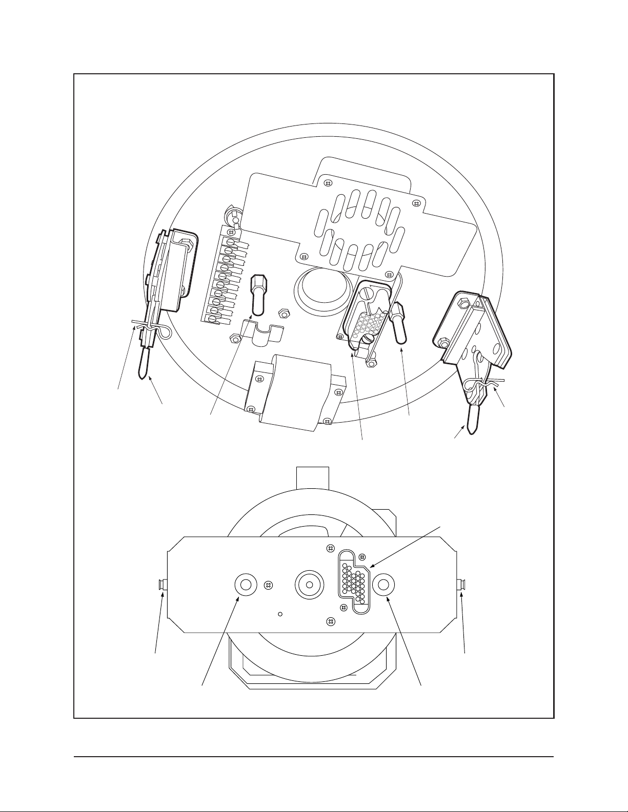
BACK BOX
HAIRPIN
CLIP
LATCH
GUIDE PIN GUIDE PIN
HAIRPIN
CLIP
DOME DRIVE
UPPER BRACKET
LATCH PIN
25-PIN CONNECTOR
BUSHING
Figure 1. Back Box and Dome Drive Components
LATCH
25-PIN
CONNECTOR
LATCH PIN
BUSHING
Pelco Manual C458M-B (1/98) 9
Page 10

Figure 2. Camera/Lens Wiring Diagram
10 Pelco Manual C458M-B (1/98)
Page 11

3.3 CAMERA/LENS INSTALLATION
Install the camera/lens you have selected for use with the IDS14 series dome as
follows:
1. Loosen the 1/4-20 lens support fastener (item 1 in Figure 3) and slide lens
support down.
2. Attach camera/lens to the tilt table with the 1/4-20 x 3/4" bolt, flat washer, and
lock washer (items 2 in Figure 3) that are provided.
If the camera/lens can be balanced on the tilt table, the life of the dome drive
will be extended.
3. Now slide the lens support up to the lens and, if applicable, fasten with
the 1/4-20 x 1/2" bolt, flat washer, and lock washer (items 3 in Figure 3) that
are provided.
4. Connect camera power spade lugs, coax video cable and lens connector, paying
special attention to the routing of your cabling so as not to interfere with the
camera/lens swing.
Proceed to Section 3.4, ADJUSTMENTS.
3.4 ADJUSTMENTS
1. Turn on the power. If, the unit has an integral receiver/driver, it will begin to
move in about 15 seconds and go through its start-up routine.
2. Refer to the manual for the camera/lens to set the switches on the camera as
required for your application.
(2)
(3)
(1)
Figure 3. Attaching Camera/Lens to Tilt Table
Pelco Manual C458M-B (1/98) 11
Page 12

NOTE:
The tilt limit stops are not
adjustable.
3. Models with 355° Rotation Only - Adjust the pan limit stops:
a. Pan the unit to the desired left position.
b. Turn off the power.
c. Position the limit stop and tighten it in place. Refer to Figure 4 for the
location of the limit steps. Disconnect the drive from the back box, if necessary, to make the adjustment.
CAUTION:
Do not remove or reposition the
fixed limit stop. Damage
will occur.
NOTE:
Vari-speed unit clearance
can easily be checked without turning power on. Fixed speed units
must have power on and you will
have to be able to activate the tilt
functions. Do not rotate fixed speed
dome drives by hand as damage
will occur to the motors.
WARNING:
Failure to
install the gasket properly
will void the warranty.
To remove the dome drive:
1. Remove the hairpin clips from the latches.
2. Open one of the latches.
3. Grasp the unit with one hand to prepare for the 10- to 13-pound
(4.5 to 5.9 kg) load.
4. Open the other latch and lower the dome drive.
d. Replace the dome drive if it was removed and turn on the power. Check
the position of the limit stop to make sure it is correct. If the position of the
stop is not correct, repeat steps a-d.
e. Repeat steps a-d for the right limit stop.
4. Install the dome liner: Push the studs on the liner into the dome bracket. Make
sure the window slot is aligned with the lens.
Ensure there is sufficient clearance between the camera/lens and dome liner.
Tilt the camera/lens combination up and down to check for clearance between
the lens and the dome liner. If proper clearance is not achieved, the dome liner will
be dislodged from the dome drive. Also pay attention to camera and wiring clearance inside the back box. Reposition the camera/lens and wiring as necessary.
5. Suspended/Hard Ceiling Models - Attach the trim ring and dome to the back
box.
Pendant Models - Align the three bezel pins with the large hole in the back
box brackets, push the bezel up and rotate clockwise to latch.
Attach the back box gasket to the rim of the back box to provide an air-tight
seal between the back box and the bezel.
6. The installation is complete. For operating instructions, refer to the receiver/
drive manual.
LIMIT STOP
LIMIT STOP
Figure 4. Pan Limit Stops (Only Two Shown)
12 Pelco Manual C458M-B (1/98)
Page 13

Regularly scheduled maintenance will prolong the operational life and appearance
of the equipment.
Clean the dome with a nonabrasive cleaning cloth and antistatic cleaner that is safe
for use on acrylic plastic. Do not use kerosene or similar substances that can scratch
the surface.
The dome drive should also be inspected and any dust and debris blown off. Pay
special attention to the spur gear drives. After removing dust and debris a film of
silicone lubricant should be applied to both pan and tilt spur gears for prolonged
gear life. It is recommended that the unit be checked at six-month intervals.
No adjustments are required.
4.1 DOME DRIVE REMOVAL
1. Pendant Models Only - Remove the gasket from the rim of the back box.
2 Remove the back box trim ring or bezel. To remove a bezel, turn it about 1/2"
(1.27 cm) counterclockwise and pull down.
3. Turn off the power.
4. Remove the hairpin clips from the latches.
5. Open one of the latches.
4.0 MAINTENANCE
6. Grasp the unit with one hand to prepare for the 10- to 13-pound (4.5 to 5.9 kg)
load.
7. Open the other latch and lower the dome drive.
Pelco Manual C458M-B (1/98) 13
Page 14

5.0 WIRING DIAGRAMS
Figure 5. 24 VAC Back Box Wiring Diagram (For Dome Drives with Integral Receiver/Driver)
14 Pelco Manual C458M-B (1/98)
Page 15

Figure 6. 120 VAC Back Box Wiring Diagram (For Dome Drives with Integral Receiver/Driver)
Pelco Manual C458M-B (1/98) 15
Page 16

Figure 7. 230 VAC Back Box Wiring Diagram (For Dome Drives with Integral Receiver/Driver)
16 Pelco Manual C458M-B (1/98)
Page 17

Figure 8. Wiring Diagram for Dome Drives with 355° Rotation
Pelco Manual C458M-B (1/98) 17
Page 18

Figure 9. Wiring Diagram for Dome Drives with 360° Rotation
18 Pelco Manual C458M-B (1/98)
Page 19

Figure 10. Wiring Diagram for Hard-Wire Systems
Pelco Manual C458M-B (1/98) 19
Page 20

6.0 EXPLODED ASSEMBLY DIAGRAMS
1
2
3
4
8
5
49
6
7
39
47
46
45
42
41
40
38
REMOVE BEFORE
OPERATING
25
36
61
44
43
48
9
60
65
29
30
34
51
10
11
12
13
14
23
21
22
36
28
56
31
27
52
24
50
15
20
19
26
16
17
18
54
55
33
53
32
Figure 11. DD14 Series Dome Drive Exploded Assembly Mechanical Parts Diagram
20 Pelco Manual C458M-B (1/98)
Page 21

Table A. DD14 Series Dome Drive Exploded Assembly Mechanical Part List (Figure 11)
Item Quantity Description Part Number
1 2 Bushing 80010004
2 2 Push nut 80010011
3 1 Upper drive mount bracket 8004034COMP
4 2 Dome drive latch pin 8004145COMP
5 1 Slip ring, 10-lead (360° models only) SR10-1
6 1 Spindle 8004004COMP
7 3 Pan limit stop (355° models only) 80010050
8 1 25-position connector receptacle CON10J025Z41T
9 1 Pan limit pin bracket (355° models only) 8004013COMP
10 1 Pan gear 80010012
11 4 Thrust washer 90010002
12 2 Thrust bearing 90010001
13 1 Bronze bearing 90010029
14 1 Pan bearing boss 8004002COMP
15 1 Backplane *
16 1 Power supply *
17 1 CPU controller *
18 1 Video board *
19 1 Receiver/driver cover 8004010COMP
(models with integral receiver/driver only)
20 1 Bracket, receiver PCB guides 8004009COMP
(models with integral receiver/driver only)
21 1 Dome drive frame 8141000WA
22 1 Tilt gear 80010013
23 1 Tilt shaft 8004018COMP
24 1 Tilt table 8104005COMP
25 1 Grommet (355° models only) GRO2172N
26 6 PCB board guides MMS300-4.25
(models with integral receiver/driver only)
27 1 Bracket, receiver PC board guide 8004008COMP
(models with integral receiver/driver only)
28 2 Motor gear 80010101
29 1 Pan spindle nut 9004004COMP
30 1 Gear, preset, pan spindle (preset models only) 8004006COMP
31 1 Dome bracket 8144001COMP
32 1 ABS dome liner 81410002
33 4 Ball stud PT180410000
34 4 Ball stud receiver PT180410001
35 2 Tilt switch with actuator SWI111SM1
36 2 Pan switch with actuator (355° models only) SWI111SM
37 — Not used
38 1 Tilt motor:
Stepper, DC, vari-speed, type 3 drive 8008000
24 VAC, 7 rpm, w/gearhead, type 1 drive 8008207
24 VAC, 14 rpm, w/gearhead, type 2 drive 8008214
39 1 Pan limit pin (355° models only) 8004011COMP
* Refer to dome receiver/driver manual for part number.
continued on next page
Pelco Manual C458M-B (1/98) 21
Page 22

Table A (continued)
Item Quantity Description Part Number
40 2 Sealed bearing 80010000
41 1 Wave spring 80010002
42 1 Boss, bearing, tilt 8004000COMP
43 1 Encoder, preset tilt (preset models only) ENCS1-512
44 1 Gear, preset tilt (preset models only) 28010017
45 1 Encoder, preset pan (preset models only) ENCS1-512I
46 1 Bracket, pan preset encoder (preset models only) 8004012COMP
47 1 Gear, pan preset encoder (preset models only) PT250010002
48 2 Snap ring (355° models only) 15510000
49 3 Spindle stand-off 8004123COMP
50 1 Lens support 8144006COMP
51 1 Rear dome bracket 8144009COMP
52 1 Front dome bracket 8144007COMP
53 1 Dome plate (receiver side) 8144002COMP
54 1 Dome plate (tilt side) 8144003COMP
55 1 Dome bracket, tilt side 8144004COMP
56 1 Pan motor:
Stepper, DC, vari-speed, type 3 drive 8008000
24 VAC, 24 rpm, w/gearhead, type 1 drive 8008224
24 VAC, 48 rpm, w/gearhead, type 2 drive 8008248
57 1 Connector, mating, lens:
9-pin, PP lens (not shown) 1751000COMP
6-pin, non-PP lens (not shown) CONMAS6100
58 1 Connector, lens, panel mount:
9-pin, PP lens (not shown) CON206705-1
6-pin, non-PP lens (not shown) CONMAB6100
59 9 Pins, loose piece (not shown) CON66399-1
(for use with item #58, CON206705-1)
60 1 Shim ZHSHIM.047
61 1 Adapter, connector (non-preset models only) 30014025COMP
62 1 Gland (355° models only) EH400010003
63 1 Strain relief bracket (355° models only) 8004064COMP
64 1 Gland nut (355° models only) EH400010004
65 1 Shipping stabilizer bracket 8144012COMP
(** Remove Before Operating** )
66 Spacer:
1 Tilt motor, (vari-speed) (not shown) 8004023COMP
1 Tilt motor, (AC) (not shown) 8004061COMP
22 Pelco Manual C458M-B (1/98)
Page 23

O
Q
F
N
E
D
N
BB
C
V
H
N
L
W
L
N
J
L
DD
P
T
M
S
N
L
F
N
G
CC
I
K
B
N
R
Q
Y
V
Z
P
J
N
N
L
L
N
X
U
L
N
AA
N
L
L
N
N
L
N
L
N
B
N
EE
A
L
L
Figure 12. DD14 Series Dome Exploded Assembly Hardware Diagram
Pelco Manual C458M-B (1/98) 23
Page 24

Table B. DD14 Series Dome Drive Exploded Assembly Hardware Parts List (Figure 12)
Item Quantity Description Part Number
A 4 Spacer, 1/4" O.D. x 1/8" L, #6 clear SPA8500
B Nut, 6-32 ZH6-32NUTSH
14 (355° models only)
10 (360° models only)
C 2 Screw, 8-32 x 3/8", hex head ZH8-32X.375HMSS
(355° models only)
D 2 Spacer 1/4" hex x 1/2" L, 6-32 tapped SPA8423
E 2 Screw, 1/4-20 x 1" flat head, Phillips ZH1/420X1.00SFS
F 5 Screw, 6-32 x 3/8" pan head, Phillips ZH6-32X.375SPP
G 3 Screw, 8-32 x 3/4" L, flat head, Phillips ZH8-32X.750SFS
H Screw, 6-32 x 3/8" flat head, Phillips ZH6-32X.375SFP
2 (355° models only)
6 (360° models only)
I 2 Screw, 8-32 x 1/2" flat head, Phillips ZH8-32X.500SFS
J 5 Screw, 8-32 x 3/8" flat head, Phillips ZH8-32X.375SFP
K Screw, 2-56 x 7/16" pan head, Phillips ZH2-56X.437SPP
8 (355° models only)
4 (360° models only)
L 33 Screw, 6-32 x 3/8" pan head, Phillips, black ZH6-32X.375BPP
M 3 Internal star washer, #4 (preset models only) ZH4LWSIS
N Internal star washer, #6 ZH6LWSIS
47 (355° models only)
43 (360° models only)
O 3 Screw, 8-32 x 1/2" pan head, Phillips ZH8-32X.500SPP
P 2 Split lock washer, 1/4" ZH1/4LWSSL
Q 11 Internal star washer, #8 ZH8LWSIS
R 8 Flat washer, #8 ZH188X435X60C
S 3 Screw, 4-40 x 1/4" pan head, Phillips ZH4-40X.250SPP
(preset models only)
T 1 Screw, 1/4-20 x 1/2", hex head ZH1/4-20X.500CH
U 1 Flat washer ZH260X562X65C
V 2 Set screw, 8-32 x 1/4", black (355° models only) ZH8-32X.250S
W 4 Set screw, 8-32 x 3/16", black ZH8-32X.187S
X 1 Screw, 10-32 x 1/2" flat head, Phillips ZH10-32X.500CFS
Y 8 Screw, 8-32 x 1/2" hex soc ZH8-32X.500CS
Z 1 Screw, 1/4-20 x 3/4" hex head ZH1/420X.750CH
AA 4 Nylon washer ZH131X361X62N
BB 2 Screw, 6-32 x 1/2" pan head, Phillips ZH6-32X.500SPP
CC 4 Screw, 6-32 x 5/8" flat head, Phillips ZH6-32X.625SFS
(355° models only)
DD 1 Flat washer, 3/16" ZH260X562X65C
EE 8 Screw, 6-32 x 3/8" flat head, black ZH6-32X.375BPF
24 Pelco Manual C458M-B (1/98)
Page 25

MECHANICAL
7.0 SPECIFICATIONS
Pan: Movement in horizontal plane:
Tilt: -90° movement from horizontal plane
Pan and Tilt
Speeds: The following speeds are available and pre-selected by cus-
Motors: Synchronous, continuous duty, instantaneous reversing
0-355° with pan limit stops
360° without pan limit stops
tomer at time of order:
Dome Drive
Type Pan Speed Tilt Speed
DD14B1L 12°/sec ± 1° 6°/sec ±.5°
DD14B1L-H
DD14C1L
DD14C1L-H
DD14D1L
DD14B2L 24°/sec ± 1° 12°/sec ±.5°
DD14B2L-H
DD14C2L
DD14C2L-H
DD14D2L
DD14E2L
DD14C3L Variable (0 – 100°/sec) 0–40°/sec ±.5°
DD14E3L
(models with fixed pan speed)
Stepper (models with variable pan speed)
Maximum
Camera/Lens
Length: Approx. 4.7" W x 3.2" H x 11.5" L (11.94 cm x 8.13 cm x 29.21 cm),
Connectors
Video: BNC
Lens: Hirschmann 6-pin (mate supplied) for non-preset models
Camera Power: Spade lugs
Gearing: Spur gear
Bearings
Pan: Roller thrust bearings and Oilite bronze bushing
Tilt: Sealed ball bearing
Braking: Models with fixed pan speed: Friction
including BNC cable connection to camera
AMP CPC 9-pin (mate supplied) for preset models
Models with variable pan speed: Magnetic locking
Pelco Manual C458M-B (1/98) 25
Page 26

ELECTRICAL
Power
Requirements: Variable Speed Unit All Others
Pan and Tilt 24 vA 7.5 vA
Idle 15 vA 2.5 vA
Maximum Current: 2 amps per conductor (360° models only)
Camera Power: 24 VAC
Limit Switches
Pan: 5 amp, external adjustment (355° models only)
Tilt: 5 amp (factory set)
GENERAL
Construction
Pan/Tilt: Aluminum with stainless steel hardware
Dome Liner: Plastic
Max. Weight: 10.7 lbs (4.85 kg). (Combined weight of dome drive with integral
receiver/driver and dome.)
(Design and product specifications subject to change without notice.)
This equipment contains electrical or electronic components that must be recycled properly to comply with Directive 2002/96/EC of the European Union
regarding the disposal of waste electrical and electronic equipment (WEEE). Contact your local dealer for procedures for recycling this equipment.
26 Pelco Manual C458M-B (1/98)
Page 27

NOTES
Pelco Manual C458M-B (1/98) 27
Page 28

8.0 WARRANTY AND RETURN INFORMATION
WARRANTY
Pelco will repair or replace, without charge, any merchandise proved defective in material or
workmanship for a period of one year after the date of shipment.
Exceptions to this warranty are as noted below:
• Five years on FT/FR8000 Series fiber optic products.
• Three years on Genex
• Three years on Camclosure
CC3751H-2, CC3651H-2X, MC3651H-2, and MC3651H-2X camera models, which have a fiveyear warranty.
• Two years on standard motorized or fixed focal length lenses.
• Two years on Legacy
dome products.
• Two years on Spectra
continuous motion applications.
• Two years on Esprit
• Eighteen months on DX Series digital video recorders, NVR300 Series network video
recorders, and Endura
• One year (except video heads) on video cassette recorders (VCRs). Video heads will be
covered for a period of six months.
• Six months on all pan and tilts, scanners or preset lenses used in continuous motion applications
(that is, preset scan, tour and auto scan modes).
Pelco will warrant all replacement parts and repairs for 90 days from the date of Pelco shipment.
All goods requiring warranty repair shall be sent freight prepaid to Pelco, Clovis, California. Repairs
made necessary by reason of misuse, alteration, normal wear, or accident are not covered under
this warranty.
Pelco assumes no risk and shall be subject to no liability for damages or loss resulting from the
specific use or application made of the Products. Pelco’s liability for any claim, whether based on
breach of contract, negligence, infringement of any rights of any party or product liability, relating
to the Products shall not exceed the price paid by the Dealer to Pelco for such Products. In no event
will Pelco be liable for any special, incidental or consequential damages (including loss of use, loss
of profit and claims of third parties) however caused, whether by the negligence of Pelco or
otherwise.
The above warranty provides the Dealer with specific legal rights. The Dealer may also have
additional rights, which are subject to variation from state to state.
If a warranty repair is required, the Dealer must contact Pelco at (800) 289-9100 or (559) 292-1981
to obtain a Repair Authorization number (RA), and provide the following information:
1. Model and serial number
2. Date of shipment, P.O. number, Sales Order number, or Pelco invoice number
3. Details of the defect or problem
If there is a dispute regarding the warranty of a product which does not fall under the warranty
conditions stated above, please include a written explanation with the product when returned.
Method of return shipment shall be the same or equal to the method by which the item was received
by Pelco.
®
Series products (multiplexers, server, and keyboard).
®
and fixed camera models, except the CC3701H-2, CC3701H-2X,
®
, CM6700/CM6800/CM9700 Series matrix, and DF5/DF8 Series fixed
®
, Esprit®, ExSite™, and PS20 scanners, including when used in
®
and WW5700 Series window wiper (excluding wiper blades).
™
Series distributed network-based video products.
RETURNS
In order to expedite parts returned to the factory for repair or credit, please call the factory at (800)
289-9100 or (559) 292-1981 to obtain an authorization number (CA number if returned for credit,
and RA number if returned for repair).
All merchandise returned for credit may be subject to a 20% restocking and refurbishing charge.
Goods returned for repair or credit should be clearly identified with the assigned CA or RA number
and freight should be prepaid. Ship to the appropriate address below.
If you are located within the continental U.S., Alaska, Hawaii or Puerto Rico, send goods to:
Service Department
Pelco
3500 Pelco Way
Clovis, CA 93612-5699
If you are located outside the continental U.S., Alaska, Hawaii or Puerto Rico and are instructed
to return goods to the USA, you may do one of the following:
If the goods are to be sent by a COURIER SERVICE, send the goods to:
Pelco
3500 Pelco Way
Pelco, the Pelco logo, Camclosure, Esprit,
Genex, Legacy, and Spectra are registered
trademarks of Pelco.
Endura and ExSite are trademarks of Pelco.
© Copyright 1998, Pelco. All rights reserved.
If the goods are to be sent by a FREIGHT FORWARDER, send the goods to:
Clovis, CA 93612-5699 USA
Pelco c/o Expeditors
473 Eccles Avenue
South San Francisco, CA 94080 USA
Phone: 650-737-1700
Fax: 650-737-0933
28 Pelco Manual C458M-B (1/98)
 Loading...