

Page 1
®
PT780-24P/PPPSA
PT780-24SL/PPSA
Pan/Tilts
Installation/
Operation Manual
C342M-PSA (11/98)
Pelco • 300 W. Pontiac Way, Clovis • CA 93612-5699 USA • Pelco Online @ http://www.pelco.com
In North America and Canada: Tel (800) 289-9100 or FAX (800) 289-9150 • DataFAX (800) 289-9108
International Customers: Tel (1-559) 292-1981 or FAX (1-559) 348-1120 • DataFAX (1-559) 292-0435
Page 2

CONTENTS
Section Page
1.0 GENERAL ...................................................................................................5
1.1 IMPORTANT SAFEGUARDS AND WARNINGS ...............................5
2.0 DESCRIPTION .......................................................................................... 6
2.1 MODELS............................................................................................6
3.0 INSTALLATION ..........................................................................................7
3.1 MOUNTING .......................................................................................7
3.2 ENCLOSURE INSTALLATION ..........................................................7
3.3 ELECTRICAL INSTALLATION...........................................................7
3.3.1 LRD41A1 1-X Legacy Receiver/Drivers.................................7
3.3.2 All Control Equipment Except LRD41A11-X
Legacy Receiver/Drivers ...................................................... 8
3.4 PAN AND TILT LIMIT STOP ADJUSTMENTS ..................................12
3.5 FINAL INSTALLATION......................................................................15
4.0 OPERATION.............................................................................................17
5.0 MAINTENANCE ........................................................................................17
6.0 EXPLODED ASSEMBL Y DIAGRAMS ......................................................19
7.0 WIRING DIAGRAM...................................................................................25
8.0 SPECIFICATIONS .................................................................................... 26
9.0 WARRANTY AND RETURN INFORMATION ...........................................28
2
2 Pelco Manual C342M-PSA (11/98)
Page 3

LIST OF ILLUSTRATIONS
Figure Page
1 Connector Assembly ..........................................................................9
2 Wiper On/Off Connection...................................................................9
3 Removing the Screws .......................................................................12
4 Releasing the Covers .......................................................................12
5 Removing the Covers .......................................................................12
6 Hooking Cover Halves ......................................................................12
7 Tilt Limit Adjustment..........................................................................13
8 Pan Limit Adjustment ........................................................................14
9 Silicone Application Locations for Inverted Unit................................15
10 Replacing the Cover Halves .............................................................15
11 Securing the Cover Halves ...............................................................16
12 Silicone Application Location for Upright Unit ...................................16
13 Pan/Tilt Adjustments .........................................................................17
14 Exploded Assembly Diagram of Mechanical Parts ...........................19
15 Exploded Assembly Diagram of Mechanical Parts
16 Exploded Assembly Diagram of Hardware .......................................23
17 PT780-24P/PPPSA and PT780-24SL/PPSA Wiring Diagram ..........25
18 PT780-24P/PPPSA and PT780-24SL/PPSA Dimension Drawing ....27
(Modifications to Figure 14) ..............................................................22
LIST OF TABLES
Table Page
A 37-Position Connector Pin Designations ..........................................10
B Requirements to Wire Power to Pan and Tilt Motors ........................11
C Maximum Cable Distances Using RB24 or RB115 Relay Boxes......11
D Mechanical Parts List (Figure 14) .....................................................20
E Mechanical Parts List (Figure 15) .....................................................22
F Hardware Parts List (Figure 16) ........................................................24
REVISION HISTORY
Manual # Date Comments
C342M-PSA 1/97 Original version.
9/97 Revised Figure 17 to move note A from pin 30 to pins 9
12/97 Changed ENGPT780-24P/PP to PT780-24P/PPPSA and
11/98 Revised procedures in Section 5.0, Maintenance.
and 14. Revised Table A to show that pins 30 and 4 are
used for sync signal and that pins 9 and 14 are not
used on ENGPT780-24SL/P. Changed manual to new
format.
changed ENGPT780-24SL/P to PT780-24SL/PPSA.
Repaginated manual.
Pelco Manual C342M-PSA (11/98) 3
3
Page 4

(This page intentionally left blank.)
4 Pelco Manual C342M-PSA (11/98)
4
Page 5
1.0 GENERAL
1.1 IMPORTANT SAFEGUARDS AND WARNINGS
Prior to installation and use of this product, the following WARNINGS should be
observed.
1. Installation and servicing should only be done by qualified service personnel
and conform to all local codes.
2. The weight of the camera/lens and enclosure shall not exceed 52 lb (23.59 kg).
3. Only use replacement parts recommended by Pelco.
4. After replacement/repair of this unit’s electrical components, conduct a resistance measurement between line and exposed parts to verify the exposed
parts have not been connected to line circuitry.
5. The installation method and materials should be capable of supporting four
times the weight of the enclosure, pan/tilt, camera and lens combination.
The product and/or manual may bear the following marks:
This symbol indicates that dangerous voltage constituting a
risk of electric shock is present within this unit.
This symbol indicates that there are important operating and
maintenance instructions in the literature accompanying this
unit.
CAUTION:
RISK OF
ELECTRIC SHOCK.
DO NOT OPEN.
TO REDUCE THE RISK OF ELECTRICAL SHOCK,
DO NOT REMOVE COVER. NO USER-
SERVICEABLE PARTS INSIDE. REFER SERVICING
TO QUALIFIED SERVICE PERSONNEL.
CAUTION:
Please thoroughly familiarize yourself with the information
in this manual prior to installation and operation.
Pelco Manual C342M-PSA (11/98) 5
Page 6

2.0 DESCRIPTION
The PT780-24P/PPPSA and PT78024SL/PPSA pan/tilt units are designed for medium-duty, indoor/outdoor use.
The PT780-24P/PPPSA pan/tilt is designed for use with the EH4718L/WPSA and
EH4718L/PSA environmental enclosures.
The PT780-24SL/PPSA pan/tilt is designed for use with the EH4718LDB/WPSA
environmental enclosure.
Pelco’s RediLINK™ connector makes it simple and quick to install an enclosure.
The weight of the enclosure with camera and lens must not exceed 52 pounds
(23.56 kg).
You can easily remove the clamshell covers from the sides of the pan/tilt units to
access all internal parts without having to remove the camera enclosure. This makes
it easy to service the units and to adjust the pan and tilt limit stops.
2.1 MODELS
PT780-24P/PPPSA Heavy-duty, indoor/outdoor pan/tilt with preset positioning
PT780-24SL/PPSA Medium-duty, indoor/outdoor pan/tilt with preset positioning
capabilities. 24 VAC.
capabilities and 360° pan rotation. 24 VAC.
6 Pelco Manual C342M-PSA (11/98)
Page 7

3.1 MOUNTING
3.0 INSTALLATION
NOTE:
To insure proper wiring and
operation of your equipment, it is recommended that you test the pan/tilt
unit and associated equipment in your
facility before installing it in the field.
Refer to Sections 3.2 through 3.4.
CAUTION:
The PT780
pan/tilt units are designed
for upright or inverted (base
up) operation. Never mount
the pan/tilt horizontally.
NOTE:
If you mount your pan/tilt unit
in the inverted position, you must install a rain cover (part number
90010019).
Attach the pan/tilt unit to a wall or ceiling mount. Follow the instructions that are
provided with the mount. Make sure the mounting surface and the selected mount
can support four times the combined weight of the pan/tilt unit and the camera
enclosure (including the camera and lens). The pan/tilt unit weighs approximately
21.5 pounds (9.68 kg). Refer to the manuals for your enclosure, camera, and lens
for the weights of those items.
Proceed to Section 3.2, ENCLOSURE INSTALLATION.
3.2 ENCLOSURE INST ALLATION
Attach the camera enclosure to the pan/tilt unit. Follow the instructions that are
provided with the enclosure.
Proceed to Section 3.3, ELECTRICAL INSTALLATION.
3.3 ELECTRICAL INSTALLATION
3.3.1 LRD41A11-X Legacy Receiver/Drivers
WARNING:
damage to the wiper, if your
To prevent
Connect the 37-pin round connector from the pan/tilt unit to the mating connector
on the receiver/driver.
enclosure has one, AC high
to turn on the wiper (pin 25
of the 37-pin connector) must
come from the same circuit
that provides power to the
wiper (pin 15 of the 37-pin
connector). This is because
the wiper and the on/off control share the same AC neutral (pin 16). See Figure 2.
Pelco Manual C342M-PSA (11/98) 7
Page 8

3.3.2 All Control Equipment Except
LRD41A11-X Legacy Receiver/Drivers
Make the interconnecting cable to link the 37-pin round connector from the pan/tilt
unit to the control equipment.
For cable requirements, refer to the following tables:
Table A: Connector Pin Designations
Tables B and C: Requirements to Wire Power to Pan and Tilt Motors
To determine the size of wire to use for enclosure power (pins 15 and 16), add
together the wattage of the camera and the wattage of the window wiper (if the
enclosure has a wiper). The wattage of the wiper is 25 watts.
If the pan/tilt has the optional heater blanket, the heater blanket requires 40 watts of
power (pins 31 and 32).
The following are some recommended common installation practices:
• For unshielded conductors, use jacketed, stranded, multiconductor cable, with
additional conductors than needed for future servicing and/or additions. Use
color-coded conductors for ease of wiring and to identify functions at a later
date.
• Keep a wiring diagram with the system for later reference.
Refer to Figure 1 and the following steps to construct the end of the cable that
connects to the pan/tilt unit:
WARNING:
To prevent
damage to the wiper , if your
enclosure has one, AC high
to turn on the wiper (pin 25
of the 37-pin connector)
must come from the same
circuit that provides power to
the wiper (pin 15 of the 37pin connector). This is because the wiper and the on/
off control share the same
AC neutral (pin 16). See Figure 2.
1. Slide the unshielded and coaxial cables through the cable shell and rubber
boot.
2. Strip one inch of the jacket from the cables.
3. For the unshielded conductors, strip 1/8 inch of insulation from the individual
wires.
4. For the coax, unwrap the braid and twist it into a single conductor. Strip 1/8
inch of insulation from the center conductor. If you are using two coax cables
- one for video output and one for camera synchronization - twist the braid
from the two coax cables together.
5. Insert the end of each wire into a socket and crimp the end of the socket over
the wire’s insulation. This provides strain relief for the bare wire. Then crimp or
solder the bare wire to the socket.
6. Refer to Table A and push each socket into the proper hole of the 37-pin connector until it snaps into place. Once a socket snaps into place, it can not be
removed without a special AMP tool.
7. Slide the cable shell down the cabling and screw it to the 37-pin connector.
8. Screw the cable clamp to the cable shell.
9. Connect the 37-pin connector to the mating connector on the pan/tilt unit.
10. To make a watertight assembly, use RTV silicone (such as Bostik #9732 or
equivalent) on both sides of the connector to fill any gaps between the cable
clamp, shell, and cable.
Proceed to Section 3.4, PAN AND TILT LIMIT STOP ADJUSTMENTS.
8 Pelco Manual C342M-PSA (11/98)
Page 9
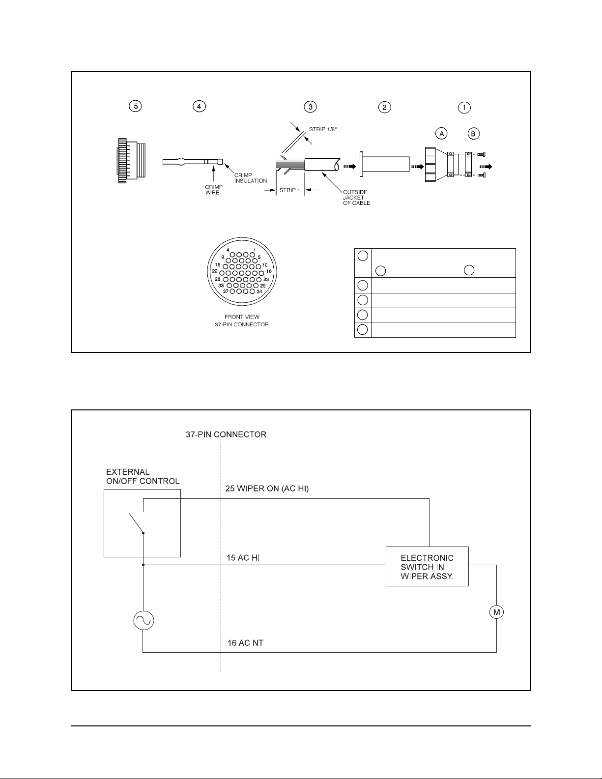
Figure 1. Connector Assembly
1 CABLE HOUSING
A SHELL B CLAMP
2 RUBBER BOOT
3 CABLE
4 SOCKET
5 CABLE PLUG (37-POSITION)
Figure 2. Wiper On/Off Connection
Pelco Manual C342M-PSA (11/98) 9
Page 10

Table A. 37-Position Connector Pin Designations
Pin # Function ENGPT780-24P/PP ENGPT780-24SL/P
Coaxial Cable
27/4 Video Signal/Ground • •
30/4 Sync Signal/Ground • •
Unshielded Conductors
3 Left • •
7 Right • •
6Up • •
5 Down • •
1 Common • •
8 Safety Ground • •
10 Iris •
11 Focus • •
12 Zoom • •
9 Spare •
14 Spare •
13 Lens Common • •
15 Enclosure Power • •
(AC High)
16 Enclosure Power • •
(AC Neutral)
31 Heater Blanket (A) (A)
(AC High)
32 Heater Blanket (A) (A)
(AC Neutral)
25 Wiper • •
26 Spare •
17 Spare •
18 Spare •
28 PP Ground • •
29 PP 5V • •
34 PP Focus • •
35 PP Zoom • •
33 PP Pan • •
36 PP Tilt • •
37 PP SL •
Pins 2 and 19-24 are not used.
10 Pelco Manual C342M-PSA (11/98)
Page 11

Table B. Requirements to Wire Power to Pan and Tilt Motors
Maximum Cable Length*
Wire Size 6 Conductors** 7 Conductors***
24 VAC
PT780-24P Models
20 AWG 59 ft. (17.98 m) 118 ft. (35.96 m)
18 AWG 94 ft. (28.65 m) 188 ft. (57.30 m)
16 AWG 149 ft. (45.41 m) 298 ft. (90.83 m)
NOTE:
Operation of the pan/tilt unit
at lower than 24 VAC will result in
reduced load and speed capability.
Table C. Maximum Cable Distances Using RB24 or RB115 Relay Boxes
* Cable distances are based on:
26.4 VAC output from the controller and
10% cable loss with both motors (pan and tilt) running simultaneously
** Six conductors for operating pan and tilt motors:
Pin number in 37-pin connector Function
3 Left
7 Right
6 Down
5Up
1 Motor Common
8 Safety Ground
*** Same as six conductors except uses two wires for motor common.
Wire Size Maximum “A” Maximum “B”
20 AWG* 5,800 ft. (1,768 m)
18 AWG 8,250 ft. (2,515 m) Use Table B
16 AWG 13,000 ft. (3,962 m)
Distance Distance
CONTROL
A
RELAY
BOX
B
REQUIRED EXTERNAL
POWER SUPPLY
* Not recommended for reliable service between control and relay box..
Pelco Manual C342M-PSA (11/98) 11
Page 12

3.4 PAN AND TILT LIMIT STOP ADJUSTMENTS
1. Remove the covers.
a. Refer to Figure 3 and remove the Phillips screw on each side of the pan/
tilt unit.
b. Refer to Figure 4 and place your hands under the cover halves. Exert a
strong, upward force to release the covers from their internal latching devices.
c. Refer to Figure 5 and pull the cover halves away from the pan/tilt unit.
d. Set the covers down or hang them by the eyelets inside the covers (refer
to Figure 6). The wire and hook on which to hang the covers is not provided.
Figure 3. Removing the Screws
Figure 5. Removing the Covers
Figure 4. Releasing the Covers
Figure 6. Hooking Cover Halves
12 Pelco Manual C342M-PSA (11/98)
Page 13

2. Adjust the tilt limit stops.
Refer to Figure 7 for the location of the tilt limit stops (item 7). Turn the control
unit on and tilt the unit to the desired up position.
Move the up limit cam until it touches the limit switch actuator. Push the cam
against the actuator until it clicks, indicating that the limit switch has opened.
Apply Lock-Tite™ to the set screw (item H) and tighten the screw on the cam.
Operate the pan/tilt to the desired down position.
Move the down limit cam until it touches the limit switch actuator. Push the
cam against the actuator until it clicks, indicating that the limit switch has
opened. Apply Lock-Tite™ to the set screw (item H) and tighten the screw on
the cam.
4
5
6
7
8
D
C
B
A
9
H
G
F
E
10
3
2
1
Figure 7. Tilt Limit Adjustment
Pelco Manual C342M-PSA (11/98) 13
Page 14

3. Adjust the pan limit stops.
NOTE:
The SL model does not have
pan limit stops.
CAUTION:
or remove the center stop.
It is for protection of wiring
inside the pan/tilt unit. If the
center stop is loosened or
removed, the wiring inside
the pan/tilt unit will be damaged.
Refer to Figure 8 for the location of the pan limit stops. Turn the control unit on
and pan the unit to the desired right limit stop.
Move the right limit stop until it touches the limit switch actuator. Push the stop
against the actuator until it clicks, indicating that the limit switch has opened.
Tighten the screw on the stop.
Operate the pan/tilt unit to check for exact positioning and adjust the stop if
necessary.
Operate the pan/tilt to the desired left limit stop.
Never loosen
Move the left limit stop until it touches the limit switch actuator. Push the stop
against the actuator until it clicks, indicating that the limit switch has opened.
Tighten the screw on the stop.
Operate the pan/tilt unit to check for exact positioning and adjust the stop if
necessary.
Proceed to Section 3.5, FINAL INSTALLATION.
00084
Figure 8. Pan Limit Adjustment
14 Pelco Manual C342M-PSA (11/98)
Page 15

3.5 FINAL INSTALLATION
1. If the pan/tilt is installed in an inverted position, refer to Figure 9 and apply
RTV silicone (such as Bostik #9732 or equivalent) to the shaded areas of the
covers.
2. Replace the covers.
a. Refer to Figure 10 and grasp one cover half in each hand and position
the covers on each side of the pan/tilt unit.
b. Bring the two cover halves together, aligning the two pins in one cover
half with the mating holes in the other cover half.
c. When the cover halves are together, press downward, as shown in Fig-
ure 11, to force the covers into their latches.
d. Replace the screws in the covers.
3. If the pan/tilt is installed in an upright position, refer to Figure 12 and apply RTV
silicone (such as Bostik #9732 or equivalent) to the shaded areas of the covers.
APPLY SILICONE SEALANT TO SHADED
AREAS BEFORE FINAL ASSEMBLY OF COVERS.
Figure 9. Silicone Application Locations for Inverted Unit
00083
Figure 10. Replacing the Cover Halves
Pelco Manual C342M-PSA (11/98) 15
Page 16

00082
Figure 11. Securing the Cover Halves
Figure 12. Silicone Application Location for Upright Unit
16 Pelco Manual C342M-PSA (11/98)
Page 17

4.0 OPERATION
Refer to the manual for your control equipment for operating the pan/tilt unit.
If your enclosure has the heater blanket option, it is thermostatically controlled to
turn on at 40°F (4.44°C) and turn off at 60°F (15.56°C). The heater blanket allows
operation of the pan/tilt unit to -50°F (-45.56°C).
5.0 MAINTENANCE
If you need to remove the enclosure, protect the RediLINK™ connector area against
moisture, dust, dirt, etc. Failure to do so could result in a bad connection. Also,
damage to the pan/tilt unit or enclosure could occur when power is turned on.
The following servicing should be done every six months with average use.
1. Remove the PT780’s outer casing. (Refer to step 1 under Section 3.4, PAN
AND TILT STOP LIMIT ADJUSTMENTS.)
2. Inspect the gaskets around the cover, tilt shaft, and spindle for damage.
3. Refer to Figure 13. It shows the parts locations of the tilt assembly. Look for
similar orientations of parts when adjusting the pan assembly.
H
G
Figure 13. Pan/Tilt Adjustments
4. Check the backlash adjustment.
Backlash is the slack or binding in a pan and tilt base mount. Determine back-
lash by lifting the mount assembly, grasping the base, and wiggling it. There
should not be any play or binding between the gear (A) and worm drive (B).
Play or binding indicates a backlash problem.
• One backlash problem involves a worm and worm gear connection loose
enough to cause slipping or tight enough to cause binding.
• The second involves a too-loose or too-tight chain, usually causing symptoms
similar to the worm and worm gear problem—slipping or binding.
a. Verify that the worm drive (B) is fully seated in the worm gear (A). If it is not:
(1) Locate the worm-driven gear for either the pan or the tilt motor linkage.
Loosen the three hex screws (F) holding the worm in place, but leave
enough thread in place to hold the assembly on the mount.
(2) Using your thumbs, gently move the worm forward or pull the assembly
back from the worm gear to either tighten or loosen the gear spacing to
the worm gear. Move the base of the pan and tilt to check the adjustment.
(3) If you get movement in the base, press a finger down in the middle of the
worm assembly. If you get no movement in the base, use your thumb
and forefinger to pull the worm assembly back until you get movement.
(4) When the spacing is correct, tighten the hex screws. Start with the middle
screw to ensure proper spacing.
(5) Remove the screw (C) in the gear train nut (D).
(6) Tighten the gear train nut to remove any play.
Pelco Manual C342M-PSA (11/98) 17
Page 18

(7) Line up the hole in the gear train nut with the nearest hole in the gear
train bracket (E).
(8) Replace the screw.
b. Refer to Figure 13. Adjust chain tension, if needed:
(1) Locate the pan or tilt motor on the assembly . Loosen the hex screws (G)
that hold the motor to its mounting bracket. Depending on which motor
assembly you are adjusting, there will be either three (pan) or four (tilt).
(Only two screws are shown in Figure 13.)
(2) Using a screwdriver, pry the motor down at H to tighten for the correct
chain tension. (You should not be able to freely move the motor with your
finger, nor should it be so tight that it will not move at all as this usually
leads to binding.)
(3) Tighten the hex screws.
c. Using a controller, you should now be able to move the PT780 without loose-
ness or binding. If you have any problems, contact Pelco’s Technical Support
Department.
5. Lubricate the chains. Use a Teflon chain lubricant, such as TriFlon™.
6. Replace the covers. (Refer to step 2 under Section 3.5, FINAL INSTALLATION.) When you reinstall the covers, apply new silicone sealant as shown in
Figures 9 and 12.
18 Pelco Manual C342M-PSA (11/98)
Page 19

6.0 EXPLODED ASSEMBLY DIAGRAMS
Figure 14. Exploded Assembly Diagram of Mechanical Parts
Pelco Manual C342M-PSA (11/98) 19
Page 20

Table D. Mechanical Parts List (Figure 14)
Item Quantity Description Part Number
1 1 Cover, pan side 9064003COMP
2 2 Ball stud PT180410000
3 2 Ball stud bracket 9064010COMP
4 1 Pan motor, 24 VAC 5708007
5 1 Pan motor gearhead 1758006
6 1 Pan motor sprocket 5804010ACOMP
7 1 Pan motor bracket 9064006COMP
8 1 Tilt preset potentiometer POTP010.0K*
9 1 Tilt potentiometer bracket 9064012COMP*
10 1 Gear, 32 teeth 28010017*
11 1 Gear, 52 teeth 28010016*
12 1 Tilt limit ring 9004012COMP
13 2 Tilt limit stop 1554050COMP
14 4 Actuator, with insulator SWIJS138B
2**
15 4 Switch SWI1SM1
2**
16 1 Upright, pan side 9064002COMP
17 1 Bushing, pan side PT250010004
18 1 26-pin, subminiature, D-type socket COND226S
19 1 Tilt shaft connector guide 9004015COMP
20 1 Tilt shaft feed-through 9004000COMP
21 5 Thrust washer, .030" 90010002
22 3 Thrust bearing 90010001
23 1 Thrust washer, .060" 90010024
24 1 Bronze bushing 90010006
25 1 Cross-brace uprights 9064008COMP
26 1 Upright, tilt side 9064001COMP
27 1 Worm gear, 40 teeth 90010009
9004024COMP***
9004025COMP****
28 1 Sprocket 90010028
29 1 Tilt motor, 24 VAC 5808000
30 1 Tilt motor gearhead 5808001
31 1 Tilt motor bracket 9064005COMP
32 1 Sprocket 5804022COMP
33 1 Circuit board assembly, 24 VAC PCB9061000ASSY
34 1 Cover, tilt side 9064004COMP
35 1 Pan spindle 9004001COMP
36 3 Pan limit stop 5804006COMP*****
37 1 Bronze bushing 90010029
38 1 Base 9064007COMP
39 1 Pan limit stop 1554049COMP*****
40 1 Slip ring 250010000***
28010000******
41 1 Preset gear, pan spindle 9004017COMP***
9004022COMP****
* PP models only **** Non-360° PP models
** All SL models ***** Not on SL models
*** SL/PP model only ****** SL model
Continued on next page
20 Pelco Manual C342M-PSA (11/98)
Page 21

Table D. Mechanical Parts List (continued)
Item Quantity Description Part Number
42 1 Pan potentiometer bracket 9004008COMP
43 1 Gear, 56 teeth 90010020*
44 1 Pan preset potentiometer POTDARM010.0K***
POTP010.0K****
45 2 Gear train nut 9004009COMP
46 4 Bronze bushing 5806005
47 8 Thrust washer 5806003
48 4 Thrust bearing 5806002
49 2 Worm 90010008
50 2 Gear train bracket 9004005COMP
51 1 3-position bar nut 9004006COMP
52 1 Sprocket PT18004003COMP
53 1 Pan spindle nut 9004004COMP
54 2 Ball stud receiver 90010030
55 1 Grommet, 3/8" ID GRO2175
Grommet, 1/4" ID GRO2170**
56 1 Wire clamp 9004020COMP*****
9004021COMP**
57 2 Eyelet service bracket 9004023COMP
58 2 Snap ring 15510000*****
59 1 Pan limit switch bracket 1554051COMP*****
60 1 Wave spring 90010017
61 1 Grommet GRO2172N*****
62 1 Unthreaded backup plate 9064015COMP
63 1 Threaded backup plate 9064014COMP
64 1 Worm gear 90010009
The following items are not shown:
65 1 Pan chain assembly, 29 pitch 9061002ASSY
66 1 Tilt chain assembly, 35 pitch 9061003ASSY
67 1 2-position plastic connector CON640428-2
68 6 3-position plastic connector CON640428-3
69 1 6-position plastic connector CON640428-6
70 2 Cover labels LBL19000
71 1 Dust protector, 26-pin, subminiature, 90010025
D-type socket
72 1 37-pin connector plug (installed on cable) CON206305-1
73 37 Connector pins CON66400-1
74 1 Cable connector clamp CON206138-1
75 1 37-pin connector socket assembly CONA37S
(loose equipment)
Includes 37-position housing, boot,
sockets, cable clamp
* PP models only **** Non-360° PP models
** All SL models ***** Not on SL models
*** SL/PP model only ****** SL model
Pelco Manual C342M-PSA (11/98) 21
Page 22

4
5
6
3
7
8
D
C
B
A
9
H
F
E
2
G
10
1
Figure 15. Exploded Assembly Diagram of Mechanical Parts (Modifications to Figure 14)
Table E. Mechanical Parts List (Figure 15)
Item Quantity Description Part Number
1 1 Pan spindle 9004027COMP
2 1 Upright, pan side 9064016COMP
3 1 Tilt shaft 9004028COMP
4 1 Switch spacer (.176") 9064019COMP
5 1 Switch spacer (.408") 9064020COMP
6 2 Switch actuator SWIJS5
7 2 Limit switch cam 9064018COMP
8 1 Potentiometer gear mount 9064021COMP
9 1 Potentiometer bracket 9064017COMP
10 1 Pan spindle snap ring 80010019
A 1 Allen screw, 10-32 x 1.00" ZH10-32X1.00CS
B 1 Split lock washer ZH10LWSSL
C 1 Flat washer, #10 ZH204X436X60C
D 3 Screw, 2-56 x .250", pan head, Phillips ZH2-56X.250SPP
E 2 Screw, 2-56 x .875", pan head, Phillips ZH2-56X.875SPP
F 4 Star lock washer, #2 ZH2LWSIS
G 2 Screw, 2-56 x .750", pan head, Phillips ZH2-56X.750SPP
H 2 Set screw, 6-32 ZH6-32X.187S
22 Pelco Manual C342M-PSA (11/98)
Page 23

EE
W
J
BB
J
W
J
CC
Q
E
F
E
F
A
B
C
D
M
T
S
PP
G
H
I
J
K
L
EE
FF
I
J
I
J
MM
LL
X
GG
Z
T
S
Y
W
J
R
S
T
J
W
BB
A*
B*
C*
D*
HH
II
JJ
KK
**
**
**
**
E
F
NN
N
D
Q
N
M
I
J
DD
E
F
P
V
U
AA
Pelco Manual C342M-PSA (11/98) 23
Figure 16. Exploded Assembly Diagram of Hardware
Page 24

Table F. Hardware Parts List (Figure 16)
Refer to Figure 15 and Table E for modifications to this list.
Item Quantity Description Part Number
A 4 Screw, 6-32 x 2 1/2-inch, pan head, Phillips ZH6-32X2.50SPP
B 4 Flat washer ZH932X1.75X130
C 4 Split lock washer, #6 ZH6LWSSL
D 4 Hex nut, 6-32 ZH6-32NUTSH
E 12 Allen screw, 10-32 x 3/8-inch ZH10-32X.375SSS
F 12 Split lock washer, #10 ZH10LWSSL
G 3 Screw, 2-56 x 3/8-inch, pan head, Phillips ZH2-56X.375SRS
H 3 Internal star washer, #2 ZH2LWSIS
I 9 Screw, 4-40 x 3/8-inch, pan head, Phillips ZH4-40X.375SPP
J 25 Internal star washer, #4 ZH4LWSIS
K 2 Screw, 8-32 x 1/4-inch, pan head, Phillips ZH8-32X.250SPP
L 2 Internal star washer, #8 ZH8LWSIS
M 8 Screw, 2-56 x 7/16-inch, pan head, Phillips ZH2-56X.437SPP
N 12 Screw, 6-32 x 1/2-inch, flat head, Phillips ZH6-32X.500FPF
O 2 Bolt, 1/4-20 x .625-inch, flat head, Phillips ZH1/420X.625SFS
P 2 Screw, 4-40 x 5/8-inch, pan head, Phillips ZH4-40X.625SPP
Q 2 Roll pin ZHPIN3/31X3/4R
R 6 Allen bolt, 1/4-20 x 1/2-inch ZH1/420X1.50SS
S 11 Flat washer, 1/4 ZH260X562X65C
T 11 Split lock washer, 1/4 ZH1/4LWSSL
U 2 Screw, 10-32 x .875-inch, gray ZH10-32X.875GRY
V 2 Thread sealing washer PS3010002
W 14 Screw, 4-40 x .250-inch, pan head, Phillips ZH4-40X.250SPP
X 2 Screw, 6-32 x .375-inch, pan head, Phillips ZH6-32X.375SPP
Y 3 Allen bolt, 1/4-20 x 3/4-inch ZH1/420X.750SS
Z 3 Bolt, 1/4-20 x 3/4-inch, flat head, Phillips ZH1/420X.750SFS
AA 2 Self-tapping screw, 6-32 ZH6-SAX.250CPP
BB 2 Roll pin ZHPIN3/23X1/2R
CC 2 Allen screw, 4-40 x .250-inch ZH4-40X.250SS
DD 2 Dowel pin 90010004
EE 1 Cover gasket 90610010
FF 1 Tilt shaft gasket 90010014
GG 1 Set screw, 6-32 x 3/16-inch ZH6-32X.187S
HH 4 Screw, 8-32 x 2 1/2-inch, pan head, Phillips, ZH8-32X2.50CPS
II 4 Flat washer ZH932X1.75X130
JJ 4 Split lock washer, #8 ZH8LWSSL
KK 4 Hex nut, 8-32 ZH8-32NUTSH
LL 1 Spindle cover gasket 90010003
MM 1 Spindle mount gasket 90010012
NN 3 Screw, 10-32 x 3/4-inch, pan head, Phillips ZH10-32X.750SPP
PP 2 Allen bolt, 1/4-20 x .625-inch ZH1/420X.625CS
24 Pelco Manual C342M-PSA (11/98)
Page 25

7.0 WIRING DIAGRAM
Figure 17. PT780-24P/PPPSA and PT780-24SL/PPSA Wiring Diagram
Pelco Manual C342M-PSA (11/98) 25
Page 26

8.0 SPECIFICATIONS
MECHANICAL
Pan Rotation: Movement in horizontal plane:
0-355°
0-360° (SL model only)
Pan Speed: 9°/sec +/-1° (no load condition)
Tilt Rotation: 90° down from horizontal
Tilt Speed: 3°/sec +/-.5° (no load condition)
Torque Output: 23.8 ft. lb (32.3 N
Maximum Load: 52 lb (23.55 kg) at specified torque
Pan/Tilt
Drive System: Delrin™ worm gear. Ground and polished stainless steel worm
Pan/Tilt Bearings: Roller thrust bearings and bronze Oilite bushings
Lubricants
Bearings: NLGI #2; Lithium complex grease fortified with molybdenum
Chain: Teflon chain lubricant (for example, TriFlon™)
Braking: Friction
ELECTRICAL
Input Voltage: 24 VAC, 50/60 Hz
vA Required: Input Voltage 24 VAC
Maximum Current: 2 amps per conductor (SL models only)
Connectors: Amp CPC type, mate supplied (37 pins)
60° up from horizontal
.
m) at rated voltage and 75° (23.9°C)
Pan 21.6 vA (.9 A)
Tilt 24 vA (1 A)
Total vA Required 45.6 vA (1.9 A)
Motor Type Single phase, instantaneous reversing, induction type. 120
Limit Switches: 5 amp, 250 VAC maximum, 10 million cycle rating, internal
GENERAL
Construction
Pan/Tilt: Aluminum exterior; painted steel and aluminum interior parts
Worm Gear: Delrin™ premium performance acetal
Worm Drive: Ground and polished stainless steel
Dimensions: See Figure 18
Environment: Indoor/outdoor
Weight
Unit: 21.5 lb (9.68 kg) approximate
Shipping: 25 lb (11.32 kg)
VAC or 24 VAC, 50/60 Hz, impedance protected. 50% duty
cycle; 30-minute rating
adjustment
-10° to 140 °F (-23° to 60°C)
(Design and product specifications subject to change without notice.)
26 Pelco Manual C342M-PSA (11/98)
Page 27

Figure 18. PT780-24P/PPPSA and PT780-24SL/PPSA Dimension Drawing
Pelco Manual C342M-PSA (11/98) 27
Page 28

9.0 WARRANTY AND RETURN INFORMATION
WARRANTY
Pelco will repair or replace, without charge, any merchandise proved defective in
material or workmanship for a period of one year after the date of shipment. Exceptions to this warranty are as noted below:
• Three years on Genex™ Series (multiplexers, server, and keyboard).
• Two years on all standard motorized and fixed focal length lenses.
• Two years on Legacy
CM9750/CM9760 Matrix, Spectra®, DF5 Series and DF8 Fixed Dome products.
• Two years on WW5700 series window wiper (excluding wiper blades).
• Two years on cameras.
• Six months on all pan and tilts, scanners or preset lenses used in continuous
motion applications (that is, preset scan, tour and auto scan modes).
Pelco will warranty all replacement parts and repairs for 90 days from the date of
Pelco shipment. All goods requiring warranty repair shall be sent freight prepaid to
Pelco, Clovis, California. Repairs made necessary by reason of misuse, alteration,
normal wear, or accident are not covered under this warranty.
Pelco assumes no risk and shall be subject to no liability for damages or loss resulting from the specific use or application made of the Products. Pelco’s liability for
any claim, whether based on breach of contract, negligence, infringement of any
rights of any party or product liability, relating to the Products shall not exceed the
price paid by the Dealer to Pelco for such Products. In no event will Pelco be liable
for any special, incidental or consequential damages (including loss of use, loss of
profit and claims of third parties) however caused, whether by the negligence of
Pelco or otherwise.
®
, Intercept®, PV1000 Series, CM6700/CM8500/CM9500/
®Pelco and the Pelco logo are
registered trademarks of Pelco.
©Copyright 1998, Pelco. All rights
reserved.
The above warranty provides the Dealer with specific legal rights. The Dealer may
also have additional rights, which are subject to variation from state to state.
If a warranty repair is required, the Dealer must contact Pelco at (800) 289-9100 or
(559) 292-1981 to obtain a Repair Authorization number (RA), and provide the
following information:
1. Model and serial number
2. Date of shipment, P.O. number, Sales Order number, or Pelco invoice number
3. Details of the defect or problem
If there is a dispute regarding the warranty of a product which does not fall under
the warranty conditions stated above, please include a written explanation with the
product when returned.
Ship freight prepaid to: Pelco
300 West Pontiac Way
Clovis, CA 93612-5699
Method of return shipment shall be the same or equal to the method by which the
item was received by Pelco.
RETURNS
In order to expedite parts returned to the factory for repair or credit, please call the
factory at (800) 289-9100 or (559) 292-1981 to obtain an authorization number (CA
number if returned for credit, and RA number if returned for repair). Goods returned
for repair or credit should be clearly identified with the assigned CA/RA number and
freight should be prepaid. All merchandise returned for credit may be subject to a
20% restocking and refurbishing charge.
Ship freight prepaid to: Pelco
300 West Pontiac Way
Clovis, CA 93612-5699
28 Pelco Manual C342M-PSA (11/98)
 Loading...