

Page 1
INSTALLATION
Pressurized
Spectra
®
IV Series
Pendant Back Box
with Fiber Optic Option
C3422M-B (3/08)
Page 2
Preinstallation
NOTE: This manual is designed to be a reference tool for the installation of your system. For best results and ease of
installation, the dome system should be assembled, pressurized, and tested before installation. A Pressurized Spectra®IV
cable harness (supplied with the back box) is required to test and monitor the pressurized dome.
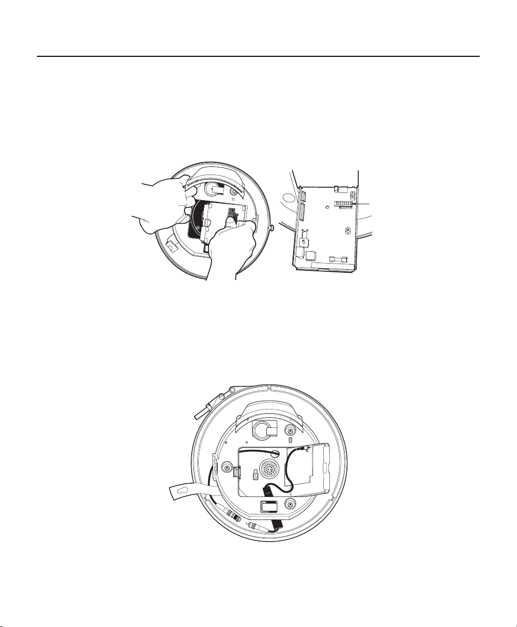
1. Install the fiber optic module: Open the hinged door to the back box by pushing the tab lock towards the wall of the
unit and lifting the door open. Remove the plug from the 16-pin connector. Install the module in the 16-pin connector.
Secure the module to the circuit board standoff using the screw and lock washer provided.
2. Connect the back box fiber optic connector to the mating connector on the module. Be sure to route the fiber optic
cables between the plastic housing and the outer wall of the back box before attaching the two connectors. Follow
all applicable instructions provided by the manufacturer of the fiber optic module.
Figure 1. IInstalling the Fiber Optic Module
16-PIN
CONNECTOR
NOTE: All bends in the fiber optic cable must be 1-inch diameter or greater.
Figure 2. Connecting the Back Box Fiber Optic Connector
2 C3422M-B (3/08)
Page 3
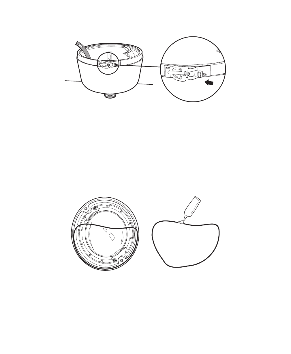
3. Loosen the V-band attached to the back box and let it hang to the side.
B
Figure 3. Loosening the V-band
4. Prepare the lower dome for installation:
a. Remove the O-ring from the lower dome.
b. Lightly apply O-ring lubricant (supplied) to the O-ring.
c. Reinstall the O-ring in the groove on the trim ring.
NOTES:
• Repeated assembly of the unit, without exercising extreme caution to protect the integrity of the O-ring and sealing
surfaces, will result in increased refilling cycles. Plan carefully to minimize service accesses.
• Use the supplied O-ring lubricant to ensure an airtight seal when installing the lower dome.
Figure 4. Applying O-Ring Lubricant
5. Attach the back box leash to the lower dome, and let the lower dome hang to the other side of the back box.
C3422M-B (3/08) 3
Page 4
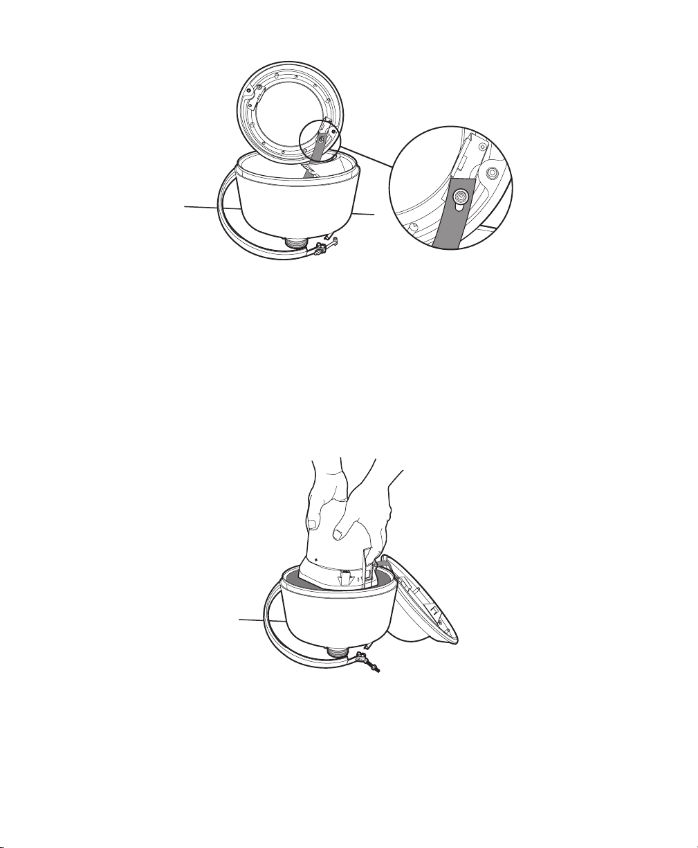
Figure 5. Attaching the Back Box Leash
6. Install the dome drive. Refer to Table A for a list of compatible dome drives and back boxes.
a. Set the DIP switches located on the base of the dome drive. Refer to the labels located on the base of the dome
drive or to Switch Settings on page 12.
b. Line up the blue and red tabs with the blue and red arrows on the hinged door inside the backbox.
c. Push in the tabs. Insert one side and then the other side. Continue pushing until both sides of the dome drive
click into place.
Figure 6. Installing the Dome Drive
4 C3422M-B (3/08)
Page 5
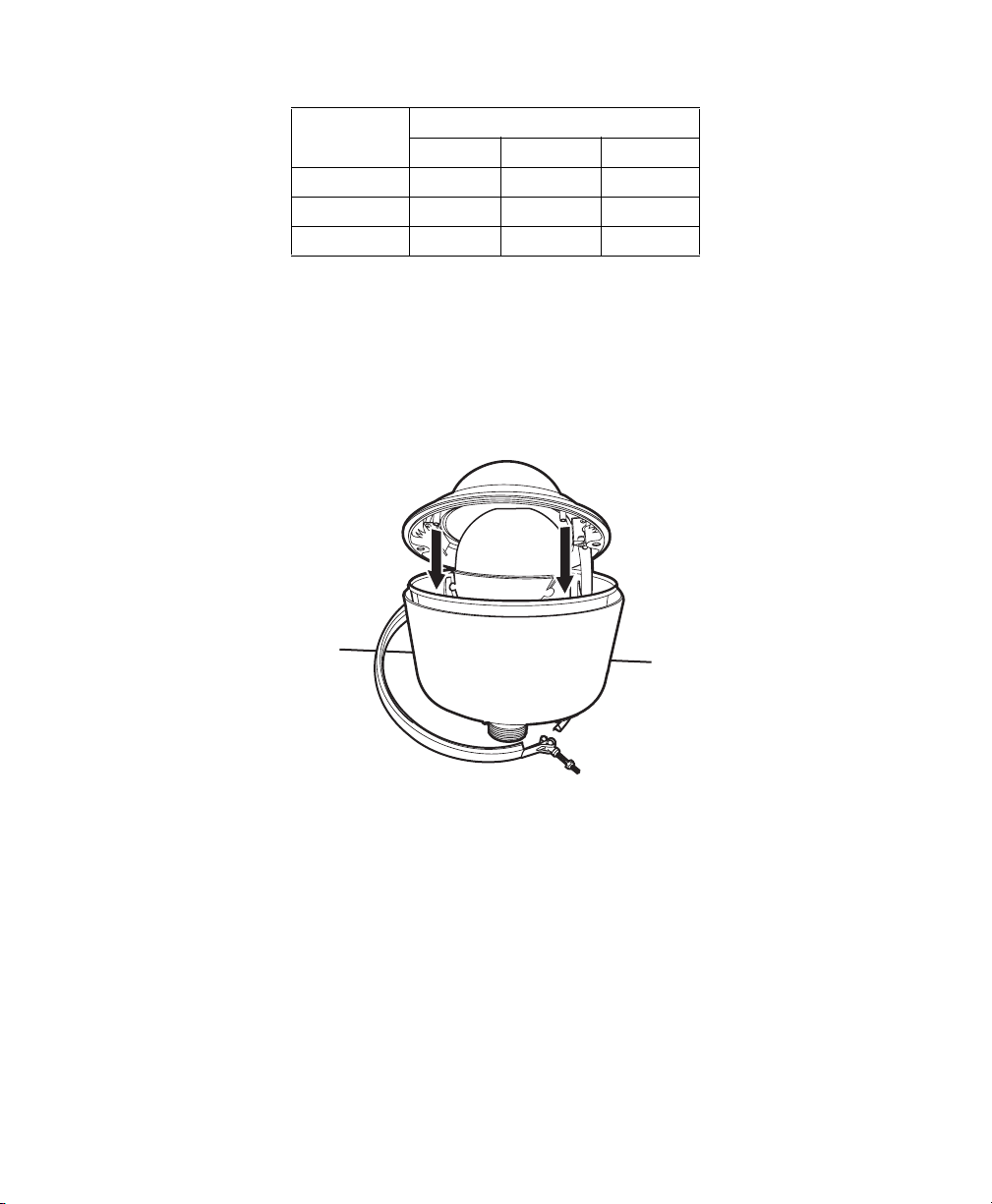
Table A. Spectra Dome Drive and Back Box Compatibility
Back Box
Dome Drive
Spectra II
Spectra III
Spectra II Spectra III Spectra IV
®
™
•
•• •
Spectra IV • • •
7. Install the lower dome:
a. Position the lower dome so that the blower duct inside the back box is between the studs attached to the inside
of the lower dome.
b. Install the V-band around the lower dome and then tighten the fastener of the V-band.
c. Test the operation of the unit before pressurizing the dome.
Figure 7. Installing the Lower Dome
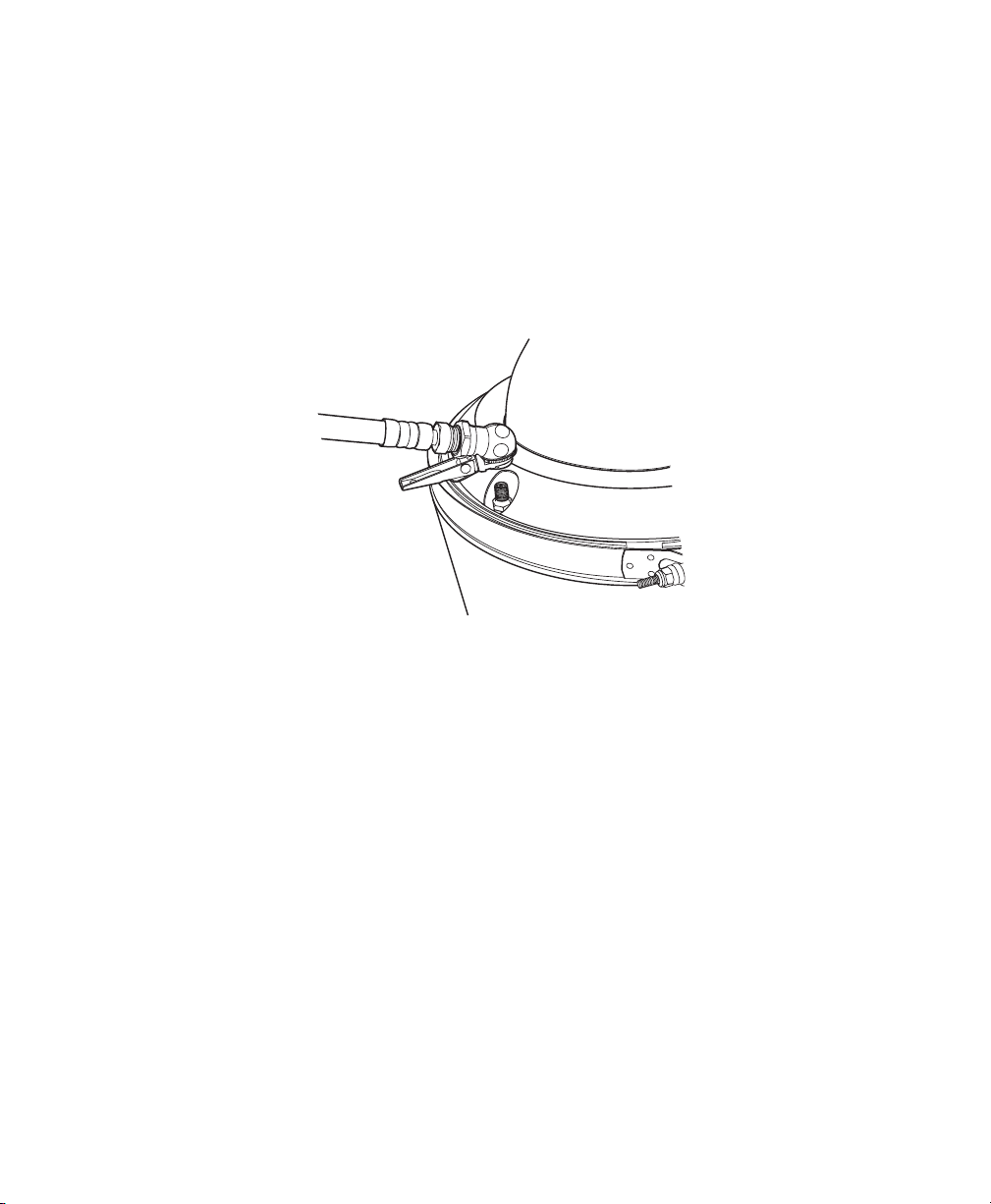
8. Pressurize the inside of the dome with nitrogen:
a. Remove the cap from the Schrader valve of the dome. Place the air chuck from the charging kit over the
Schrader valve.
NOTE: You may use your own charging equipment or Pelco’s EH8000RKIT recharge kit. If you are using your own
equipment, adjust the regulator for an output pressure of 12 psi (83 kPa).
b. Open the tank valve of the charging kit. Fill the dome with nitrogen for a minimum of five minutes to replace the
oxygen inside the dome with nitrogen.
c. Remove the air chuck and then replace the Schrader valve cap.
C3422M-B (3/08) 5
Page 6
d. Refer to the Operation/Programming manual (C3412M) for instructions on how to view the current readings for
temperature and pressure. Record the initial temperature and pressure readings of the dome in the space
provided below:
Initial Temperature _______________
Initial Pressure _________________
NOTES:
• Record the initial temperature and pressure readings for future reference. It is normal for changes in temperature to
cause dome pressure to rise and fall.
• You must perform an annual refill to be consistent with the intent of the application.
Figure 8. Pressurizing the Dome
6 C3422M-B (3/08)
Page 7

Site Installation
1. Feed a fiber optic cable (not supplied) and the supplied wiring harness into the front of the mount and out the back of
the mount. Connect the wires as required. Refer to Table B, Table C, and Table D on page 10, and Table E on page 11
for cable and wiring information. Fasten the mount to the mounting surface (refer to the instructions supplied with
the mount).
2. Remove the back box mounting plate: Loosen the nuts on top of the back box until they reach the locking material at
the end of the studs, and then turn the mounting plate clockwise and lift.
Figure 9. Wiring the Mount
C3422M-B (3/08) 7
Page 8

Figure 10. Removing the Back Box Mounting Plate
3. Thread the wiring from the mount through the mounting plate, and then attach the mounting plate to the mount.
If outdoors, apply thread compound (supplied) to the threads on the mounting plate.
Figure 11. Attaching the Mounting Plate
4. Attach the wire harness connector to the mating connector located on the top of the back box. Connect the fiber optic
cable. Insert the studs and nuts on top of the back box into the mounting plate, turn the back box counterclockwise,
and then tighten the three nuts.
8 C3422M-B (3/08)
Page 9

Figure 12. Attaching the Wire Harness Connector
C3422M-B (3/08) 9
Page 10

.
Table B. Fiber Optic Cable Types
Spectra Model Cable Type Connector
Single mode (PRS models) 9/125 μm cable ST type
Multimode (PRM models) 62.5/125 μm cable ST type
Table C. 24 VAC Wiring Distances
The following are the recommended maximum distances for 24 VAC applications and are calculated with a 10-percent
voltage drop. (Ten percent is generally the maximum allowable voltage drop for AC-powered devices.)
Wire Gauge
Tot a l VA
20 AWG
(0.5 mm
2
)
18 AWG
(1.0 mm2)
16 AWG
1.5 mm2)
14 AWG
(2.5 mm2)
73 39 ft
(12 m)
62 ft
(19 m)
98 ft
(30 m)
NOTES:
• Input power for the dome is 24 VAC only. Power consumption is 73 VA per dome.
• Use a 24 VAC transformer with a minimum of 100 VA.
.
Table D. UTP Wiring Distances
Receiver Maximum Distance
Active
(video only)
Passive
(video, Coaxitron
®
, and
0 to 3,000 ft
(0 to 914.4 m)
0 to 750 ft
(0 to 228.6 m)
Pelco V-Sync)
NOTE: As a minimum, UTP requires Cat5, 100-ohm twisted pair cable.
156 ft
(48 m)
10 C3422M-B (3/08)
Page 11

Table E. Configuration of Wire Harness
Pin Wire Color Function
9-Conductor Cable
ABlack Alarm 1
BRed Alarm 2
C White Alarm 3
DGreen Alarm 4
EBrown Alarm 5
F Orange Alarm 6
G Yellow Alarm 7
H Violet Ground
– Blue Not Used
5-Conductor Cable
J Black Relay N.O. (Aux. 1)
K Red Relay N.C. (Aux. 1)
L Green Relay Common (Aux. 1)
M Brown Ground
N White Auxilary 2
Cat5 Cable
P Green TX+
R White/Green TX-
S Blue RX+
T White/Blue RX-
U Orange UTP Video (+)
V White/Orange UTP Video (-)
W Brown Spare
X White/Brown Spare
Coaxial Cable
Y Coaxial Core Video Out
Z Coaxial Shield Video Shield
Individual Wires
a White 24 VAC (AC HI)
b Black 24 VAC (AC LO)
c Green/Yellow Earth Ground
C3422M-B (3/08) 11
Page 12

Switch Settings
WARNING: If you are using Pelco D or Pelco P protocol control, your system may not operate if the baud rate and
address switches are not set correctly. The switches are set at the factory at the defaults for Pelco D protocol
control (2400 baud and address 1).
Special Systems
Switch Number 12345678910
AD-32 Preset System ON
CM9502 Setting ON
Vicon Not currently available; SW2-3 is reserved for future use.
Serial Port Settings
Switch Number 12345678910
RS422 OFF OFF
RS485, 4-Wire OFF ON
RS485, 2-Wire ON ON
Pelco D and Pelco P Protocol Baud Rate
Switch Number 12345678910
2400 Baud (Default for Pelco D Protocol Control) OFF OFF OFF
4800 Baud (Default for Pelco P Protocol Control) ON OFF OFF
9600 Baud OFF ON OFF
Table F. Switch Settings for SW2
Video Cable Type
Switch Number 12345678910
Coax Cable OFF
UTP Cable ON
Dome Termination
Switch Number 12345678910
Terminated ON
Not Terminated OFF
12 C3422M-B (3/08)
Page 13

Table G. Switch Settings for SW1, Pelco P Protocol Control
NOTE: For Coaxitron controls, SW1 is not used; set all switches to the OFF position. For Pelco D protocol control systems, refer to
Table H on page 13.
SPECTRA
ADDRESS
10 ON OFF OFF ON OFF
11 OFF ON OFF ON OFF
12 ON ON OFF ON OFF
13 OFF OFF ON ON OFF
14 ON OFF ON ON OFF
15 OFF ON ON ON OFF
16 ON ON ON ON OFF
SW1-1 SW1-2 SW1-3 SW1-4 SW1-5
1 OFF OFF OFF OFF OFF
2 ON OFF OFF OFF OFF
3 OFF ON OFF OFF OFF
4 ON ON OFF OFF OFF
5 OFF OFF ON OFF OFF
6 ON OFF ON OFF OFF
7 OFF ON ON OFF OFF
8 ON ON ON OFF OFF
9 OFF OFF OFF ON OFF
SWITCH SETTING
SPECTRA
ADDRESS
17 OFF OFF OFF OFF ON
18 ON OFF OFF OFF ON
19 OFF ON OFF OFF ON
20 ON ON OFF OFF ON
21 OFF OFF ON OFF ON
22 ON OFF ON OFF ON
23 OFF ON ON OFF ON
24 ON ON ON OFF ON
25 OFF OFF OFF ON ON
26 ON OFF OFF ON ON
27 OFF ON OFF ON ON
28 ON ON OFF ON ON
29 OFF OFF ON ON ON
30 ON OFF ON ON ON
31 OFFONONONON
32 ON ON ON ON ON
SW1-1 SW1-2 SW1-3 SW1-4 SW1-5
SWITCH SETTING
Table H. Switch Settings for SW1, Pelco D Protocol Control
NOTE: For Coaxitron controls, SW1 is not used; set all switches to the OFFposition. For Pelco P protocol control systems, refer to
Table G on page 13.
SPECTRA
ADDRESS
SW1-1 SW1-2 SW1-3 SW1-4 SW1-5 SW1-6 SW1-7 SW1-8
1 ON OFF OFF OFF OFF OFF OFF OFF
2 OFF ON OFF OFF OFF OFF OFF OFF
3 ON ON OFF OFF OFF OFF OFF OFF
4 OFF OFF ON OFF OFF OFF OFF OFF
5 ON OFF ON OFF OFF OFF OFF OFF
6 OFF ON ON OFF OFF OFF OFF OFF
7 ON ON ON OFF OFF OFF OFF OFF
8 OFF OFF OFF ON OFF OFF OFF OFF
9 ONOFFOFFONOFFOFFOFFOFF
10 OFF ON OFF ON OFF OFF OFF OFF
11 ON ON OFF ON OFF OFF OFF OFF
12 OFF OFF ON ON OFF OFF OFF OFF
13 ON OFF ON ON OFF OFF OFF OFF
14 OFF ON ON ON OFF OFF OFF OFF
15 ON ON ON ON OFF OFF OFF OFF
SWITCH SETTING
SPECTRA
ADDRESS
SW1-1 SW1-2 SW1-3 SW1-4 SW1-5 SW1-6 SW1-7 SW1-8
16 OFF OFF OFF OFF ON OFF OFF OFF
17 ON OFF OFF OFF ON OFF OFF OFF
18 OFF ON OFF OFF ON OFF OFF OFF
19 ON ON OFF OFF ON OFF OFF OFF
20 OFF OFF ON OFF ON OFF OFF OFF
21 ON OFF ON OFF ON OFF OFF OFF
22 OFF ON ON OFF ON OFF OFF OFF
23 ON ON ON OFF ON OFF OFF OFF
24 OFF OFF OFF ON ON OFF OFF OFF
25 ON OFF OFF ON ON OFF OFF OFF
26 OFF ON OFF ON ON OFF OFF OFF
27 ON ON OFF ON ON OFF OFF OFF
28 OFF OFF ON ON ON OFF OFF OFF
29 ON OFF ON ON ON OFF OFF OFF
30 OFFONONONONOFFOFFOFF
SWITCH SETTING
C3422M-B (3/08) 13
Page 14

SPECTRA
ADDRESS
SW1-1 SW1-2 SW1-3 SW1-4 SW1-5 SW1-6 SW1-7 SW1-8
31 ON ON ON ON ON OFF OFF OFF
32 OFF OFF OFF OFF OFF ON OFF OFF
33 ON OFF OFF OFF OFF ON OFF OFF
34 OFF ON OFF OFF OFF ON OFF OFF
35 ON ON OFF OFF OFF ON OFF OFF
36 OFF OFF ON OFF OFF ON OFF OFF
37 ON OFF ON OFF OFF ON OFF OFF
38 OFF ON ON OFF OFF ON OFF OFF
39 ON ON ON OFF OFF ON OFF OFF
40 OFF OFF OFF ON OFF ON OFF OFF
41 ON OFF OFF ON OFF ON OFF OFF
42 OFF ON OFF ON OFF ON OFF OFF
43 ON ON OFF ON OFF ON OFF OFF
44 OFF OFF ON ON OFF ON OFF OFF
45 ON OFF ON ON OFF ON OFF OFF
46 OFF ON ON ON OFF ON OFF OFF
47 ON ON ON ON OFF ON OFF OFF
48 OFF OFF OFF OFF ON ON OFF OFF
49 ON OFF OFF OFF ON ON OFF OFF
50 OFF ON OFF OFF ON ON OFF OFF
51 ON ON OFF OFF ON ON OFF OFF
52 OFF OFF ON OFF ON ON OFF OFF
53 ON OFF ON OFF ON ON OFF OFF
54 OFF ON ON OFF ON ON OFF OFF
55 ON ON ON OFF ON ON OFF OFF
56 OFF OFF OFF ON ON ON OFF OFF
57 ON OFF OFF ON ON ON OFF OFF
58 OFF ON OFF ON ON ON OFF OFF
59 ON ON OFF ON ON ON OFF OFF
60 OFF OFF ON ON ON ON OFF OFF
61 ON OFF ON ON ON ON OFF OFF
62 OFF ON ON ON ON ON OFF OFF
63 ON ON ON ON ON ON OFF OFF
64 OFF OFF OFF OFF OFF OFF ON OFF
65 ON OFF OFF OFF OFF OFF ON OFF
66 OFF ON OFF OFF OFF OFF ON OFF
67 ON ON OFF OFF OFF OFF ON OFF
68 OFF OFF ON OFF OFF OFF ON OFF
69 ON OFF ON OFF OFF OFF ON OFF
70 OFF ON ON OFF OFF OFF ON OFF
SWITCH SETTING
SPECTRA
ADDRESS
SW1-1 SW1-2 SW1-3 SW1-4 SW1-5 SW1-6 SW1-7 SW1-8
71 ON ON ON OFF OFF OFF ON OFF
72 OFF OFF OFF ON OFF OFF ON OFF
73 ON OFF OFF ON OFF OFF ON OFF
74 OFF ON OFF ON OFF OFF ON OFF
75 ON ON OFF ON OFF OFF ON OFF
76 OFF OFF ON ON OFF OFF ON OFF
77 ON OFF ON ON OFF OFF ON OFF
78 OFF ON ON ON OFF OFF ON OFF
79 ON ON ON ON OFF OFF ON OFF
80 OFF OFF OFF OFF ON OFF ON OFF
81 ON OFF OFF OFF ON OFF ON OFF
82 OFF ON OFF OFF ON OFF ON OFF
83 ON ON OFF OFF ON OFF ON OFF
84 OFF OFF ON OFF ON OFF ON OFF
85 ON OFF ON OFF ON OFF ON OFF
86 OFF ON ON OFF ON OFF ON OFF
87 ON ON ON OFF ON OFF ON OFF
88 OFF OFF OFF ON ON OFF ON OFF
89 ON OFF OFF ON ON OFF ON OFF
90 OFF ON OFF ON ON OFF ON OFF
91 ON ON OFF ON ON OFF ON OFF
92 OFF OFF ON ON ON OFF ON OFF
93 ON OFF ON ON ON OFF ON OFF
94 OFF ON ON ON ON OFF ON OFF
95 ON ON ON ON ON OFF ON OFF
96 OFF OFF OFF OFF OFF ON ON OFF
97 ON OFF OFF OFF OFF ON ON OFF
98 OFF ON OFF OFF OFF ON ON OFF
99 ON ON OFF OFF OFF ON ON OFF
100 OFF OFF ON OFF OFF ON ON OFF
101 ON OFF ON OFF OFF ON ON OFF
102 OFF ON ON OFF OFF ON ON OFF
103 ON ON ON OFF OFF ON ON OFF
104 OFF OFF OFF ON OFF ON ON OFF
105 ON OFF OFF ON OFF ON ON OFF
106 OFF ON OFF ON OFF ON ON OFF
107 ON ON OFF ON OFF ON ON OFF
108 OFF OFF ON ON OFF ON ON OFF
109 ON OFF ON ON OFF ON ON OFF
110 OFF ON ON ON OFF ON ON OFF
SWITCH SETTING
14 C3422M-B (3/08)
Page 15

SPECTRA
ADDRESS
SW1-1 SW1-2 SW1-3 SW1-4 SW1-5 SW1-6 SW1-7 SW1-8
111 ON ON ON ON OFF ON ON OFF
112 OFF OFF OFF OFF ON ON ON OFF
113 ON OFF OFF OFF ON ON ON OFF
114 OFF ON OFF OFF ON ON ON OFF
115 ON ON OFF OFF ON ON ON OFF
116 OFF OFF ON OFF ON ON ON OFF
117 ON OFF ON OFF ON ON ON OFF
118 OFF ON ON OFF ON ON ON OFF
119 ON ON ON OFF ON ON ON OFF
120 OFF OFF OFF ON ON ON ON OFF
121 ON OFF OFF ON ON ON ON OFF
122 OFF ON OFF ON ON ON ON OFF
123 ON ON OFF ON ON ON ON OFF
124 OFF OFF ON ON ON ON ON OFF
125 ON OFF ON ON ON ON ON OFF
126 OFF ON ON ON ON ON ON OFF
127 ON ON ON ON ON ON ON OFF
128 OFF OFF OFF OFF OFF OFF OFF ON
129 ON OFF OFF OFF OFF OFF OFF ON
130 OFF ON OFF OFF OFF OFF OFF ON
131 ON ON OFF OFF OFF OFF OFF ON
132 OFF OFF ON OFF OFF OFF OFF ON
133 ON OFF ON OFF OFF OFF OFF ON
134 OFF ON ON OFF OFF OFF OFF ON
135 ON ON ON OFF OFF OFF OFF ON
136 OFF OFF OFF ON OFF OFF OFF ON
137 ON OFF OFF ON OFF OFF OFF ON
138 OFF ON OFF ON OFF OFF OFF ON
139 ON ON OFF ON OFF OFF OFF ON
140 OFF OFF ON ON OFF OFF OFF ON
141 ON OFF ON ON OFF OFF OFF ON
142 OFF ON ON ON OFF OFF OFF ON
143 ON ON ON ON OFF OFF OFF ON
144 OFF OFF OFF OFF ON OFF OFF ON
145 ON OFF OFF OFF ON OFF OFF ON
146 OFF ON OFF OFF ON OFF OFF ON
147 ON ON OFF OFF ON OFF OFF ON
148 OFF OFF ON OFF ON OFF OFF ON
149 ON OFF ON OFF ON OFF OFF ON
150 OFF ON ON OFF ON OFF OFF ON
SWITCH SETTING
SPECTRA
ADDRESS
SW1-1 SW1-2 SW1-3 SW1-4 SW1-5 SW1-6 SW1-7 SW1-8
151 ON ON ON OFF ON OFF OFF ON
152 OFF OFF OFF ON ON OFF OFF ON
153 ON OFF OFF ON ON OFF OFF ON
154 OFF ON OFF ON ON OFF OFF ON
155 ON ON OFF ON ON OFF OFF ON
156 OFF OFF ON ON ON OFF OFF ON
157 ON OFF ON ON ON OFF OFF ON
158 OFF ON ON ON ON OFF OFF ON
159 ON ON ON ON ON OFF OFF ON
160 OFF OFF OFF OFF OFF ON OFF ON
161 ON OFF OFF OFF OFF ON OFF ON
162 OFF ON OFF OFF OFF ON OFF ON
163 ON ON OFF OFF OFF ON OFF ON
164 OFF OFF ON OFF OFF ON OFF ON
165 ON OFF ON OFF OFF ON OFF ON
166 OFF ON ON OFF OFF ON OFF ON
167 ON ON ON OFF OFF ON OFF ON
168 OFF OFF OFF ON OFF ON OFF ON
169 ON OFF OFF ON OFF ON OFF ON
170 OFF ON OFF ON OFF ON OFF ON
171 ON ON OFF ON OFF ON OFF ON
172 OFF OFF ON ON OFF ON OFF ON
173 ON OFF ON ON OFF ON OFF ON
174 OFF ON ON ON OFF ON OFF ON
175 ON ON ON ON OFF ON OFF ON
176 OFF OFF OFF OFF ON ON OFF ON
177 ON OFF OFF OFF ON ON OFF ON
178 OFF ON OFF OFF ON ON OFF ON
179 ON ON OFF OFF ON ON OFF ON
180 OFF OFF ON OFF ON ON OFF ON
181 ON OFF ON OFF ON ON OFF ON
182 OFF ON ON OFF ON ON OFF ON
183 ON ON ON OFF ON ON OFF ON
184 OFF OFF OFF ON ON ON OFF ON
185 ON OFF OFF ON ON ON OFF ON
186 OFF ON OFF ON ON ON OFF ON
187 ON ON OFF ON ON ON OFF ON
188 OFF OFF ON ON ON ON OFF ON
189 ON OFF ON ON ON ON OFF ON
190 OFF ON ON ON ON ON OFF ON
SWITCH SETTING
C3422M-B (3/08) 15
Page 16

SPECTRA
ADDRESS
SW1-1 SW1-2 SW1-3 SW1-4 SW1-5 SW1-6 SW1-7 SW1-8
191 ON ON ON ON ON ON OFF ON
192 OFF OFF OFF OFF OFF OFF ON ON
193 ON OFF OFF OFF OFF OFF ON ON
194 OFF ON OFF OFF OFF OFF ON ON
195 ON ON OFF OFF OFF OFF ON ON
196 OFF OFF ON OFF OFF OFF ON ON
197 ON OFF ON OFF OFF OFF ON ON
198 OFF ON ON OFF OFF OFF ON ON
199 ON ON ON OFF OFF OFF ON ON
200 OFF OFF OFF ON OFF OFF ON ON
201 ON OFF OFF ON OFF OFF ON ON
202 OFF ON OFF ON OFF OFF ON ON
203 ON ON OFF ON OFF OFF ON ON
204 OFF OFF ON ON OFF OFF ON ON
205 ON OFF ON ON OFF OFF ON ON
206 OFF ON ON ON OFF OFF ON ON
207 ON ON ON ON OFF OFF ON ON
208 OFF OFF OFF OFF ON OFF ON ON
209 ON OFF OFF OFF ON OFF ON ON
210 OFF ON OFF OFF ON OFF ON ON
211 ON ON OFF OFF ON OFF ON ON
212 OFF OFF ON OFF ON OFF ON ON
213 ON OFF ON OFF ON OFF ON ON
214 OFF ON ON OFF ON OFF ON ON
215 ON ON ON OFF ON OFF ON ON
216 OFF OFF OFF ON ON OFF ON ON
217 ON OFF OFF ON ON OFF ON ON
218 OFF ON OFF ON ON OFF ON ON
219 ON ON OFF ON ON OFF ON ON
220 OFF OFF ON ON ON OFF ON ON
221 ON OFF ON ON ON OFF ON ON
222 OFF ON ON ON ON OFF ON ON
SWITCH SETTING
SPECTRA
ADDRESS
SW1-1 SW1-2 SW1-3 SW1-4 SW1-5 SW1-6 SW1-7 SW1-8
223 ON ON ON ON ON OFF ON ON
224 OFF OFF OFF OFF OFF ON ON ON
225 ON OFF OFF OFF OFF ON ON ON
226 OFF ON OFF OFF OFF ON ON ON
227 ON ON OFF OFF OFF ON ON ON
228 OFF OFF ON OFF OFF ON ON ON
229 ON OFF ON OFF OFF ON ON ON
230 OFF ON ON OFF OFF ON ON ON
231 ON ON ON OFF OFF ON ON ON
232 OFF OFF OFF ON OFF ON ON ON
233 ON OFF OFF ON OFF ON ON ON
234 OFF ON OFF ON OFF ON ON ON
235 ON ON OFF ON OFF ON ON ON
236 OFF OFF ON ON OFF ON ON ON
237 ON OFF ON ON OFF ON ON ON
238 OFF ON ON ON OFF ON ON ON
239 ON ON ON ON OFF ON ON ON
240 OFF OFF OFF OFF ON ON ON ON
241 ON OFF OFF OFF ON ON ON ON
242 OFF ON OFF OFF ON ON ON ON
243 ON ON OFF OFF ON ON ON ON
244 OFF OFF ON OFF ON ON ON ON
245 ON OFF ON OFF ON ON ON ON
246 OFF ON ON OFF ON ON ON ON
247 ON ON ON OFF ON ON ON ON
248 OFF OFF OFF ON ON ON ON ON
249 ON OFF OFF ON ON ON ON ON
250 OFF ON OFF ON ON ON ON ON
251 ON ON OFF ON ON ON ON ON
252 OFF OFF ON ON ON ON ON ON
253 ONOFFONONONONONON
254 OFF ON ON ON ON ON ON ON
SWITCH SETTING
16 C3422M-B (3/08)
Page 17

Specifications
GENERAL
Construction
Back Box 316L stainless steel
Dome Drive Aluminum, thermoplastic
Lower Dome Trim Ring 316L stainless steel
Bubble Polycarbonate, 0.09-inch thick
V-Band 316L stainless steel
Pressure Relief Brass
Schrader Valve Brass
Connector Nickel-plated steel
Light Attenuation
Smoked f/1.0 light loss
Clear Zero light loss
Pressurization
Valve Schrader
Pressure 8 psig (not factory pressurized)
Pressure Relief 10 psig
Pan Movement 360° continuous pan rotation
Vertical Tilt +2° to -92°
Manual Pan/Tilt Speeds*
Pan 0.1° to 80°/sec manual operation, 150°/sec turbo
Tilt 0.1° to 40°/sec manual operation
Preset Speeds
Pan 400°/sec
Tilt 200°/sec
Operating Temperature (Assumes no wind chill factor)
Maximum 140°F (60°C) absolute maximum; 122°F (50°C) sustained maximum
Minimum -60°F (-51.1°C) absolute minimum; minimal icing at sustained minimum of -50°F
Weight (approximate)
Back Box 10.2 lb (4.60 kg)
Dome Drive 3.3 lb (1.48 kg)
Lower Dome 3.3 lb (1.48 kg)
(-45°C); prevents icing at sustained minimum of -40°F (-40°C); de-ices 0.1 inch
(2.5 mm) within 3 hours after power-up
ELECTRICAL (Dome Drive Only)
Input Voltage 18-32 VAC; 24 VAC nominal
22-27 VDC; 24 VDC nominal
*For variable-speed operation, an appropriate controller is required. With fixed-speed controllers, pan/tilt speed is
20°/sec. The CM6700/CM6800 controller with the KBD200A keyboard has programmable fixed speeds.
C3422M-B (3/08) 17
Page 18

Input Power
24 VAC 73 VA nominal (with heater)
24 VDC 3 A nominal (with heater)
Fuse 1.25 A
Auxiliary Outputs 2
Alarm Inputs 7
10.6 (26.7)
11.6
(29.5)
5.9 (15.1)
NOTE: VALUES IN PARENTHESES ARE CENTIMETERS;
ALL OTHERS ARE INCHES.
18 C3422M-B (3/08)
Page 19

PRODUCT WARRANTY AND RETURN INFORMATION
WARRANTY
Pelco will repair or replace, without charge, any merchandise proved defective
in material or workmanship for a period of one year after the date of
shipment.
Exceptions to this warranty are as noted below:
• Five years on fiber optic products and TW3000 Series unshielded twisted
pair (UTP) transmission products.
• Three years on Spectra
• Three years on Genex
keyboard).
• Three years on DX Series digital video recorders, DVR5100 Series digital
video recorders, DigitalSENTRY
digital video recorders, NVR300 Series network video recorders, and
®
Endura
Series distributed network-based video products.
• Three years on Camclosure
except the CC3701H-2, CC3701H-2X, CC3751H-2, CC3651H-2X,
MC3651H-2, and MC3651H-2X camera models, which have a five-year
warranty.
• Three years on PMCL200/300/400 Series LCD monitors.
• Two years on standard motorized or fixed focal length lenses.
• Two years on Legacy
DF5/DF8 Series fixed dome products.
• Two years on Spectra III
scanners, including when used in continuous motion applications.
• Two years on Esprit and WW5700 Series window wiper (excluding wiper
blades).
• Two years (except lamp and color wheel) on Digital Light Processing (DLP
displays. The lamp and color wheel will be covered for a period of 90 days.
The air filter is not covered under warranty.
• Two years on Intelli-M
• One year (except video heads) on video cassette recorders (VCRs). Video
heads will be covered for a period of six months.
• Six months on all pan and tilts, scanners, or preset lenses used in
continuous motion applications (preset scan, tour, and auto scan modes).
Pelco will warrant all replacement parts and repairs for 90 days from the date of
Pelco shipment. All goods requiring warranty repair shall be sent freight prepaid
to a Pelco designated location. Repairs made necessary by reason of misuse,
alteration, normal wear, or accident are not covered under this warranty.
®
IV products.
®
Series products (multiplexers, server, and
®
Series hardware products, DVX Series
®
and Pelco-branded fixed camera models,
®
, CM6700/CM6800/CM9700 Series matrix, and
™
, Spectra Mini, Esprit®, ExSite®, and PS20
®
eIDC controllers.
Pelco assumes no risk and shall be subject to no liability for damages or loss
resulting from the specific use or application made of the Products. Pelco’s
liability for any claim, whether based on breach of contract, negligence,
infringement of any rights of any party or product liability, relating to the
Products shall not exceed the price paid by the Dealer to Pelco for such
Products. In no event will Pelco be liable for any special, incidental, or
consequential damages (including loss of use, loss of profit, and claims of third
parties) however caused, whether by the negligence of Pelco or otherwise.
The above warranty provides the Dealer with specific legal rights. The Dealer
may also have additional rights, which are subject to variation from state to
state.
If a warranty repair is required, the Dealer must contact Pelco at
(800) 289-9100 or (559) 292-1981 to obtain a Repair Authorization number
(RA), and provide the following information:
1. Model and serial number
2. Date of shipment, P.O. number, sales order number, or Pelco invoice number
3. Details of the defect or problem
If there is a dispute regarding the warranty of a product that does not fall
under the warranty conditions stated above, please include a written
explanation with the product when returned.
Method of return shipment shall be the same or equal to the method by which
the item was received by Pelco.
RETURNS
®
To expedite parts returned for repair or credit, please call Pelco at
)
(800) 289-9100 or (559) 292-1981 to obtain an authorization number (CA
number if returned for credit, and RA number if returned for repair) and
designated return location.
All merchandise returned for credit may be subject to a 20 percent restocking
and refurbishing charge.
Goods returned for repair or credit should be clearly identified with the
assigned CA or RA number and freight should be prepaid.
The materials used in the manufacture of this document and its components are compliant to the requirements of Directive 2002/95/EC.
This equipment contains electrical or electronic components that must be recycled properly to comply with Directive 2002/96/EC of the European Union
regarding the disposal of waste electrical and electronic equipment (WEEE). Contact your local dealer for procedures for recycling this equipment.
REVISION HISTORY
Manual # Date Comments
C3422M 9/06 Original version.
C3422M-A 11/06 Inserted Spectra III compatibility note. Added serial port settings to Table F.
C3422M-B 3/08 Added information to Preinstallation section regarding the use of O-ring lubricant to create an airtight seal.
Pelco, the Pelco logo, Camclosure, DigitalSENTRY, Endura, Esprit, ExSite, Genex, Intelli-M, Lega cy, and Spectra are registered trademarks of Pelco, Inc.
Spectra III is a trademark of Pelco, Inc. © Copyright 2008, Pelco, Inc. All rights reserved.
DLP is a registered trademark of Texas Instruments Incorporated.
Vicon is a trademark of Vicon Industries, Inc.
Page 20

Worldwide Headquarters
3500 Pelco Way
Clovis, California 93612 USA
USA & Canada
Tel: 800/289-9100
Fax: 800/289-9150
International
Tel: 1-559/292-1981
Fax: 1-559/348-1120
www.pelco.com
ISO9001
Australia|Finland|France|Germany|Italy|Macau|The Netherlands|Russia|Singapore
South Africa
Spain|Sweden|United Arab Emirates|United Kingdom|United States
|
 Loading...