

Page 1
INSTALLATION
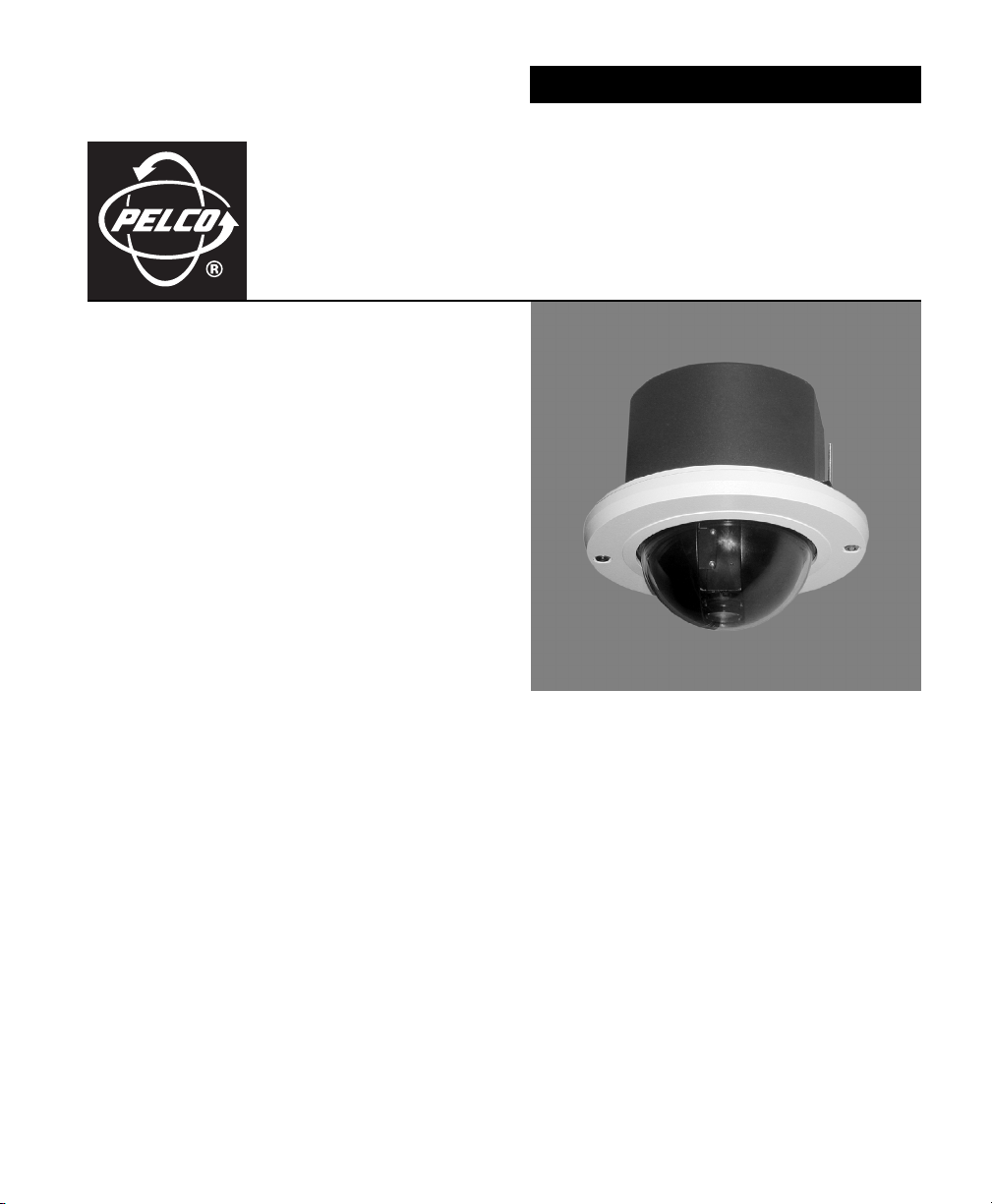
Heavy-Duty
Spectra® IV Series
In-Ceiling Back Box
C3419M-B (11/06)
Page 2
Installation
BACK
MOUNTING
PLATES
CEILING
1
2
4
MOUNTING
RING
5
36
2 C3419M-B (11/06)
Page 3
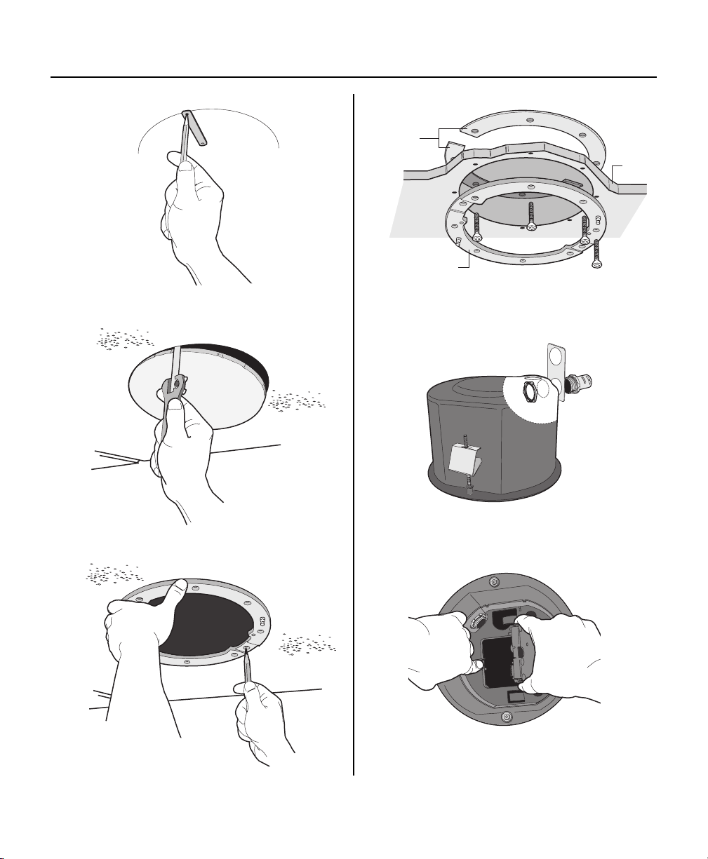
1. Locate the center point of the mounting location and insert the compass tool. Draw a circle.
2. Cut the circle out of the ceiling.
3. Use the mounting ring as a template and mark the screw hole pattern onto the mounting surface. Prepare the holes.
4. Install the mounting plates. Use the eight 10-32 x 3-inch screws (supplied) and install the mounting ring (A) and two
back mounting plates (B).
a. Line up the mounting ring with the eight fastener holes.
b. Feed one back mounting plate (B) through the hole in the ceiling (C) and line up with four fastener holes.
c. Install fasteners through the mounting ring (A), ceiling, and out the back mounting plate (B).
d. Install second back mounting plate (B).
5. Attach the conduit fitting, lock nut, and safety chain bracket. Install a safety chain/cable (not supplied) that will
support up to 16 pounds (7.3 kg).
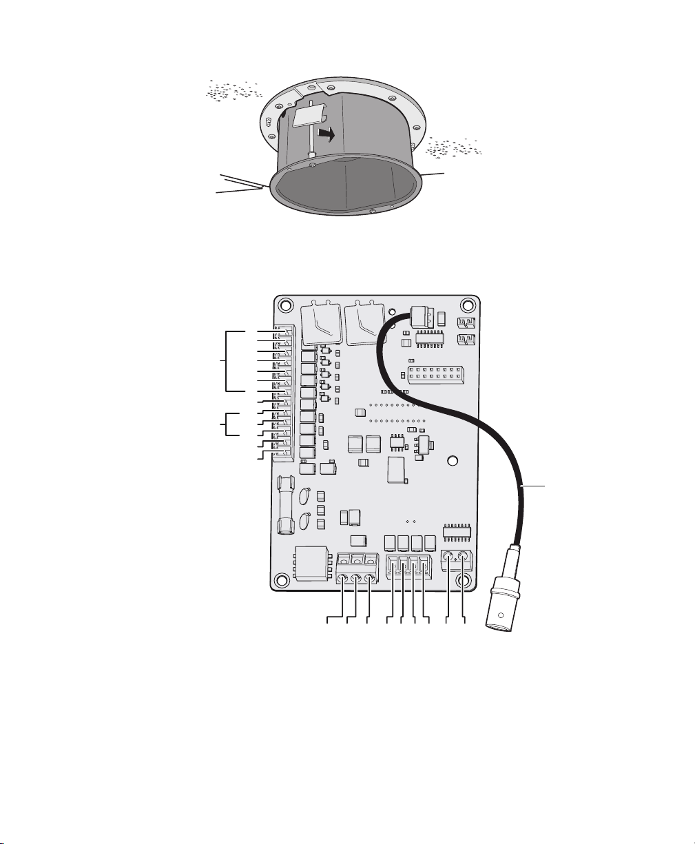
6. Open the hinged door to the back box. Push the tab lock towards the wall of the unit and lift the door open.
Pull wiring into the back box through the conduit fitting. Refer to Table A, Table B, and Table C for wiring distances.
Table A. Video Coaxial Cable
Requirements
Cable Type* Maximum Distance
RG59/U 750 ft (229 m)
RG6/U 1,000 ft (305 m)
RG11/U 1,500 ft (457 m)
*Cable requirements:
75 ohms impedance
All-copper center conductor
All-copper braided shield with 95% braid
coverage
NOTE: Input power for the dome is 24 VAC or 24 VDC. Using 24 VAC input power, power consumption is 23 VA per dome.
Using 24 VDC input power, power consumption is 0.7 A (15 watts). Use a 24 VAC transformer with a minimum of 40 VA per
dome.
.
NOTE: As a minimum, UTP requires Cat5, 100-ohm twisted pair cable.
The following are the recommended maximum distances for 24 VAC
and 24 VDC applications and are calculated with a 10 percent voltage
drop. (Ten percent is generally the maximum allowable voltage drop
for AC- or DC-powered devices.)
AC/DC
Tot a l VA/
Total Watts
23 VA/
15 watts
Table C. UTP Wiring Distances
Receiver Maximum Distance
Active
(Video Only)
Passive
(Video, Coaxitron, Pelco V-Sync)
Table B. 24 VAC/24VDC Wiring Distances
Wire Gauge
20 AWG
(0.5 mm
123 ft
(38 m)
2
)
18 AWG
(1.0 mm2)
196 ft
(60 m)
16 AWG
(1.5 mm2)
311 ft
(95 m)
0-3,000 ft
(0-914.4 m)
0-750 ft
(0-228.6 m)
14 AWG
(2.5 mm2)
495 ft
(151 m)
C3419M-B (11/06) 3
Page 4
7
1
2
3
GND
COM
AUX2
GND
4
5
6
7
NO
NC
VIDEO
ALARMS
8
AUX1
UTP+ UTP-RX- RX+ TX+TX-PWR- PWR+GND
4 C3419M-B (11/06)
Page 5

7. Install the back box by compressing the spring clips and pushing the back box through the hole. Tighten the screws
until you hear a clicking noise.
WARNING: An electrical short in the back box may occur if the metal BNC connector is not completely covered by
the protective boot.
8. Connect wiring to the circuit board inside the back box. When finished, close the door to the back box and turn on the
power. The green LED will light.
NOTES:
• Aux 1: Maximum 2 A at low voltage (<40 V)
Aux 2: Maximum 30 mA at 32 VDC
• If you are using both unshielded twisted pair (UTP) wiring and a translator board, install the UTP wiring before
installing the translator board.
C3419M-B (11/06) 5
Page 6

SWITCH 1 AND 2
9
10
11
TRIM LEASH
BARREL
KEY LOCK
BALL STUD
BALL STUD
RECEIVER
6 C3419M-B (11/06)
Page 7

9. Configure DIP switches SW1 and SW2 located on the top of the dome drive. For DIP switch settings, refer to the
labels located on the top of the dome drive or to the Switch Settings section of this manual.
NOTE: When connecting more than one Spectra
®
dome to a single controller, terminate the unit farthest from the
controller. To terminate the dome drive set the SW2-10 switch to the ON position.
10. Install the dome drive. Refer to Table D for a list of a compatible dome drives and back boxes. Line up the blue and
red tabs with the blue and red arrows on the hinged door inside the back box. Push in on the tabs. Insert one side and
then the other side. Continue pushing on the ends of the tabs until both sides click into place.
Table D. Spectra Dome Drive and Back Box Compatibility
Dome Drive
Spectra II
Spectra III
Spectra II Spectra III Spectra IV
®
™
•
•• •
Back Box
Spectra IV • • •
11. Install the lower dome. Snap the clip of the lower trim ring leash (D) into the hole on the lip of the back box. Insert
both keys in the barrel locks (E). Turn keys clockwise to the unlocked position. Keys cannot be removed from lock in
the unlocked position. Align ball studs (F) (located on the mount ring) with the ball stud receptacles (G) (located on
the inside of the lower dome). Place the lower dome over the back box. Hold and turn both keys to the locked
position.
To use your dome, refer to the operation and programming manual.
Troubleshooting
If your dome does not power up properly after installation, use the following steps.
1. Check the fuse on the circuit board inside the back box for continuity. Replace the fuse if needed.
2. Check the wiring with a volt meter to ensure proper voltage is being received into the back box.
If your dome powers up correctly, but you do not have accurate control, use the following steps.
1. Check the signal with a volt meter or an oscilloscope.
NOTE: This step will not apply if you are using Coaxitron control.
2. Ensure that the switch settings on the dome drive are set correctly. Refer to the Switch Settings section.
3. If you are using a Pelco controller, ensure that the factory-installed 16-pin jumper has not been removed. If you are
using a third-party controller, a TXB Series translator board must be installed. The dome will not function without this
16-pin jumper or a translator board installed.
C3419M-B (11/06) 7
Page 8

Switch Settings
WARNING: If you are using D-type or P-type control, your system may not operate if the baud rate and address
switches are not set correctly. The switches are set at the factory at the defaults for D-type control (2400 baud and
address 1).
Special Systems
Switch Number 12345678910
AD-32 Preset System ON
CM9502 Setting ON
Vicon
Serial Port Settings
Switch Number 12345678910
RS422 OFF OFF
RS485, Four Wire OFF ON
RS485, Two Wire ON ON
D or P Protocol Baud Rate
Switch Number 12345678910
2400 Baud (Default for D-type Control) OFF OFF OFF
4800 Baud (Default for P-type Control) ON OFF OFF
9600 Baud OFF ON OFF
Table E. Switch Settings for SW2
Not currently available; SW2-3 is reserved for future use.
Video Cable Type
Switch Number 12345678910
Coax Cable OFF
UTP Cable ON
Dome Termination
Switch Number
Ter mi na te d
Not Terminated
8 C3419M-B (11/06)
12345678910
ON
OFF
Page 9

Table F. Switch Settings for SW1, P-Type Control
NOTE: For Coaxitron controls, SW1 is not used; set all switches OFF. For D-type control systems, refer to Table G.
SPECTRA
ADDRESS
10 ON OFF OFF ON OFF
11 OFF ON OFF ON OFF
12 ON ON OFF ON OFF
13 OFF OFF ON ON OFF
14 ON OFF ON ON OFF
15 OFF ON ON ON OFF
16 ON ON ON ON OFF
SW1-1 SW1-2 SW1-3 SW1-4 SW1-5
1 OFF OFF OFF OFF OFF
2 ON OFF OFF OFF OFF
3 OFF ON OFF OFF OFF
4 ON ON OFF OFF OFF
5 OFF OFF ON OFF OFF
6 ON OFF ON OFF OFF
7 OFF ON ON OFF OFF
8 ON ON ON OFF OFF
9 OFF OFF OFF ON OFF
SWITCH SETTING
Table G. Switch Settings for SW1, D-Type Control
NOTE: For Coaxitron controls, SW1 is not used; set all switches OFF. For P-type control systems, refer to Table F.
SPECTRA
ADDRESS
SW1-1 SW1-2 SW1-3 SW1-4 SW1-5 SW1-6 SW1-7 SW1-8
1 ON OFF OFF OFF OFF OFF OFF OFF
2 OFF ON OFF OFF OFF OFF OFF OFF
3 ON ON OFF OFF OFF OFF OFF OFF
4 OFF OFF ON OFF OFF OFF OFF OFF
5 ON OFF ON OFF OFF OFF OFF OFF
6 OFF ON ON OFF OFF OFF OFF OFF
7 ON ON ON OFF OFF OFF OFF OFF
8 OFF OFF OFF ON OFF OFF OFF OFF
9 ONOFFOFFONOFFOFFOFFOFF
10 OFF ON OFF ON OFF OFF OFF OFF
11 ON ON OFF ON OFF OFF OFF OFF
12 OFF OFF ON ON OFF OFF OFF OFF
13 ON OFF ON ON OFF OFF OFF OFF
14 OFF ON ON ON OFF OFF OFF OFF
15 ON ON ON ON OFF OFF OFF OFF
SWITCH SETTING
SPECTRA
ADDRESS
17 OFF OFF OFF OFF ON
18 ON OFF OFF OFF ON
19 OFF ON OFF OFF ON
20 ON ON OFF OFF ON
21 OFF OFF ON OFF ON
22 ON OFF ON OFF ON
23 OFF ON ON OFF ON
24 ON ON ON OFF ON
25 OFF OFF OFF ON ON
26 ON OFF OFF ON ON
27 OFF ON OFF ON ON
28 ON ON OFF ON ON
29 OFF OFF ON ON ON
30 ON OFF ON ON ON
31 OFFONONONON
32 ON ON ON ON ON
SPECTRA
ADDRESS
16 OFF OFF OFF OFF ON OFF OFF OFF
17 ON OFF OFF OFF ON OFF OFF OFF
18 OFF ON OFF OFF ON OFF OFF OFF
19 ON ON OFF OFF ON OFF OFF OFF
20 OFF OFF ON OFF ON OFF OFF OFF
21 ON OFF ON OFF ON OFF OFF OFF
22 OFF ON ON OFF ON OFF OFF OFF
23 ON ON ON OFF ON OFF OFF OFF
24 OFF OFF OFF ON ON OFF OFF OFF
25 ON OFF OFF ON ON OFF OFF OFF
26 OFF ON OFF ON ON OFF OFF OFF
27 ON ON OFF ON ON OFF OFF OFF
28 OFF OFF ON ON ON OFF OFF OFF
29 ON OFF ON ON ON OFF OFF OFF
30 OFFONONONONOFFOFFOFF
SW1-1 SW1-2 SW1-3 SW1-4 SW1-5
SW1-1 SW1-2 SW1-3 SW1-4 SW1-5 SW1-6 SW1-7 SW1-8
SWITCH SETTING
SWITCH SETTING
C3419M-B (11/06) 9
Page 10

SPECTRA
ADDRESS
SW1-1 SW1-2 SW1-3 SW1-4 SW1-5 SW1-6 SW1-7 SW1-8
31 ON ON ON ON ON OFF OFF OFF
32 OFF OFF OFF OFF OFF ON OFF OFF
33 ON OFF OFF OFF OFF ON OFF OFF
34 OFF ON OFF OFF OFF ON OFF OFF
35 ON ON OFF OFF OFF ON OFF OFF
36 OFF OFF ON OFF OFF ON OFF OFF
37 ON OFF ON OFF OFF ON OFF OFF
38 OFF ON ON OFF OFF ON OFF OFF
39 ON ON ON OFF OFF ON OFF OFF
40 OFF OFF OFF ON OFF ON OFF OFF
41 ON OFF OFF ON OFF ON OFF OFF
42 OFF ON OFF ON OFF ON OFF OFF
43 ON ON OFF ON OFF ON OFF OFF
44 OFF OFF ON ON OFF ON OFF OFF
45 ON OFF ON ON OFF ON OFF OFF
46 OFF ON ON ON OFF ON OFF OFF
47 ON ON ON ON OFF ON OFF OFF
48 OFF OFF OFF OFF ON ON OFF OFF
49 ON OFF OFF OFF ON ON OFF OFF
50 OFF ON OFF OFF ON ON OFF OFF
51 ON ON OFF OFF ON ON OFF OFF
52 OFF OFF ON OFF ON ON OFF OFF
53 ON OFF ON OFF ON ON OFF OFF
54 OFF ON ON OFF ON ON OFF OFF
55 ON ON ON OFF ON ON OFF OFF
56 OFF OFF OFF ON ON ON OFF OFF
57 ON OFF OFF ON ON ON OFF OFF
58 OFF ON OFF ON ON ON OFF OFF
59 ON ON OFF ON ON ON OFF OFF
60 OFF OFF ON ON ON ON OFF OFF
61 ON OFF ON ON ON ON OFF OFF
62 OFF ON ON ON ON ON OFF OFF
63 ON ON ON ON ON ON OFF OFF
64 OFF OFF OFF OFF OFF OFF ON OFF
65 ON OFF OFF OFF OFF OFF ON OFF
66 OFF ON OFF OFF OFF OFF ON OFF
67 ON ON OFF OFF OFF OFF ON OFF
68 OFF OFF ON OFF OFF OFF ON OFF
69 ON OFF ON OFF OFF OFF ON OFF
70 OFF ON ON OFF OFF OFF ON OFF
SWITCH SETTING
SPECTRA
ADDRESS
SW1-1 SW1-2 SW1-3 SW1-4 SW1-5 SW1-6 SW1-7 SW1-8
71 ON ON ON OFF OFF OFF ON OFF
72 OFF OFF OFF ON OFF OFF ON OFF
73 ON OFF OFF ON OFF OFF ON OFF
74 OFF ON OFF ON OFF OFF ON OFF
75 ON ON OFF ON OFF OFF ON OFF
76 OFF OFF ON ON OFF OFF ON OFF
77 ON OFF ON ON OFF OFF ON OFF
78 OFF ON ON ON OFF OFF ON OFF
79 ON ON ON ON OFF OFF ON OFF
80 OFF OFF OFF OFF ON OFF ON OFF
81 ON OFF OFF OFF ON OFF ON OFF
82 OFF ON OFF OFF ON OFF ON OFF
83 ON ON OFF OFF ON OFF ON OFF
84 OFF OFF ON OFF ON OFF ON OFF
85 ON OFF ON OFF ON OFF ON OFF
86 OFF ON ON OFF ON OFF ON OFF
87 ON ON ON OFF ON OFF ON OFF
88 OFF OFF OFF ON ON OFF ON OFF
89 ON OFF OFF ON ON OFF ON OFF
90 OFF ON OFF ON ON OFF ON OFF
91 ON ON OFF ON ON OFF ON OFF
92 OFF OFF ON ON ON OFF ON OFF
93 ON OFF ON ON ON OFF ON OFF
94 OFF ON ON ON ON OFF ON OFF
95 ON ON ON ON ON OFF ON OFF
96 OFF OFF OFF OFF OFF ON ON OFF
97 ON OFF OFF OFF OFF ON ON OFF
98 OFF ON OFF OFF OFF ON ON OFF
99 ON ON OFF OFF OFF ON ON OFF
100 OFF OFF ON OFF OFF ON ON OFF
101 ON OFF ON OFF OFF ON ON OFF
102 OFF ON ON OFF OFF ON ON OFF
103 ON ON ON OFF OFF ON ON OFF
104 OFF OFF OFF ON OFF ON ON OFF
105 ON OFF OFF ON OFF ON ON OFF
106 OFF ON OFF ON OFF ON ON OFF
107 ON ON OFF ON OFF ON ON OFF
108 OFF OFF ON ON OFF ON ON OFF
109 ON OFF ON ON OFF ON ON OFF
110 OFF ON ON ON OFF ON ON OFF
SWITCH SETTING
10 C3419M-B (11/06)
Page 11

SPECTRA
ADDRESS
SW1-1 SW1-2 SW1-3 SW1-4 SW1-5 SW1-6 SW1-7 SW1-8
111 ON ON ON ON OFF ON ON OFF
112 OFF OFF OFF OFF ON ON ON OFF
113 ON OFF OFF OFF ON ON ON OFF
114 OFF ON OFF OFF ON ON ON OFF
115 ON ON OFF OFF ON ON ON OFF
116 OFF OFF ON OFF ON ON ON OFF
117 ON OFF ON OFF ON ON ON OFF
118 OFF ON ON OFF ON ON ON OFF
119 ON ON ON OFF ON ON ON OFF
120 OFF OFF OFF ON ON ON ON OFF
121 ON OFF OFF ON ON ON ON OFF
122 OFF ON OFF ON ON ON ON OFF
123 ON ON OFF ON ON ON ON OFF
124 OFF OFF ON ON ON ON ON OFF
125 ON OFF ON ON ON ON ON OFF
126 OFF ON ON ON ON ON ON OFF
127 ON ON ON ON ON ON ON OFF
128 OFF OFF OFF OFF OFF OFF OFF ON
129 ON OFF OFF OFF OFF OFF OFF ON
130 OFF ON OFF OFF OFF OFF OFF ON
131 ON ON OFF OFF OFF OFF OFF ON
132 OFF OFF ON OFF OFF OFF OFF ON
133 ON OFF ON OFF OFF OFF OFF ON
134 OFF ON ON OFF OFF OFF OFF ON
135 ON ON ON OFF OFF OFF OFF ON
136 OFF OFF OFF ON OFF OFF OFF ON
137 ON OFF OFF ON OFF OFF OFF ON
138 OFF ON OFF ON OFF OFF OFF ON
139 ON ON OFF ON OFF OFF OFF ON
140 OFF OFF ON ON OFF OFF OFF ON
141 ON OFF ON ON OFF OFF OFF ON
142 OFF ON ON ON OFF OFF OFF ON
143 ON ON ON ON OFF OFF OFF ON
144 OFF OFF OFF OFF ON OFF OFF ON
145 ON OFF OFF OFF ON OFF OFF ON
146 OFF ON OFF OFF ON OFF OFF ON
147 ON ON OFF OFF ON OFF OFF ON
148 OFF OFF ON OFF ON OFF OFF ON
149 ON OFF ON OFF ON OFF OFF ON
150 OFF ON ON OFF ON OFF OFF ON
SWITCH SETTING
SPECTRA
ADDRESS
SW1-1 SW1-2 SW1-3 SW1-4 SW1-5 SW1-6 SW1-7 SW1-8
151 ON ON ON OFF ON OFF OFF ON
152 OFF OFF OFF ON ON OFF OFF ON
153 ON OFF OFF ON ON OFF OFF ON
154 OFF ON OFF ON ON OFF OFF ON
155 ON ON OFF ON ON OFF OFF ON
156 OFF OFF ON ON ON OFF OFF ON
157 ON OFF ON ON ON OFF OFF ON
158 OFF ON ON ON ON OFF OFF ON
159 ON ON ON ON ON OFF OFF ON
160 OFF OFF OFF OFF OFF ON OFF ON
161 ON OFF OFF OFF OFF ON OFF ON
162 OFF ON OFF OFF OFF ON OFF ON
163 ON ON OFF OFF OFF ON OFF ON
164 OFF OFF ON OFF OFF ON OFF ON
165 ON OFF ON OFF OFF ON OFF ON
166 OFF ON ON OFF OFF ON OFF ON
167 ON ON ON OFF OFF ON OFF ON
168 OFF OFF OFF ON OFF ON OFF ON
169 ON OFF OFF ON OFF ON OFF ON
170 OFF ON OFF ON OFF ON OFF ON
171 ON ON OFF ON OFF ON OFF ON
172 OFF OFF ON ON OFF ON OFF ON
173 ON OFF ON ON OFF ON OFF ON
174 OFF ON ON ON OFF ON OFF ON
175 ON ON ON ON OFF ON OFF ON
176 OFF OFF OFF OFF ON ON OFF ON
177 ON OFF OFF OFF ON ON OFF ON
178 OFF ON OFF OFF ON ON OFF ON
179 ON ON OFF OFF ON ON OFF ON
180 OFF OFF ON OFF ON ON OFF ON
181 ON OFF ON OFF ON ON OFF ON
182 OFF ON ON OFF ON ON OFF ON
183 ON ON ON OFF ON ON OFF ON
184 OFF OFF OFF ON ON ON OFF ON
185 ON OFF OFF ON ON ON OFF ON
186 OFF ON OFF ON ON ON OFF ON
187 ON ON OFF ON ON ON OFF ON
188 OFF OFF ON ON ON ON OFF ON
189 ON OFF ON ON ON ON OFF ON
190 OFF ON ON ON ON ON OFF ON
SWITCH SETTING
C3419M-B (11/06) 11
Page 12

SPECTRA
ADDRESS
SW1-1 SW1-2 SW1-3 SW1-4 SW1-5 SW1-6 SW1-7 SW1-8
191 ON ON ON ON ON ON OFF ON
192 OFF OFF OFF OFF OFF OFF ON ON
193 ON OFF OFF OFF OFF OFF ON ON
194 OFF ON OFF OFF OFF OFF ON ON
195 ON ON OFF OFF OFF OFF ON ON
196 OFF OFF ON OFF OFF OFF ON ON
197 ON OFF ON OFF OFF OFF ON ON
198 OFF ON ON OFF OFF OFF ON ON
199 ON ON ON OFF OFF OFF ON ON
200 OFF OFF OFF ON OFF OFF ON ON
201 ON OFF OFF ON OFF OFF ON ON
202 OFF ON OFF ON OFF OFF ON ON
203 ON ON OFF ON OFF OFF ON ON
204 OFF OFF ON ON OFF OFF ON ON
205 ON OFF ON ON OFF OFF ON ON
206 OFF ON ON ON OFF OFF ON ON
207 ON ON ON ON OFF OFF ON ON
208 OFF OFF OFF OFF ON OFF ON ON
209 ON OFF OFF OFF ON OFF ON ON
210 OFF ON OFF OFF ON OFF ON ON
211 ON ON OFF OFF ON OFF ON ON
212 OFF OFF ON OFF ON OFF ON ON
213 ON OFF ON OFF ON OFF ON ON
214 OFF ON ON OFF ON OFF ON ON
215 ON ON ON OFF ON OFF ON ON
216 OFF OFF OFF ON ON OFF ON ON
217 ON OFF OFF ON ON OFF ON ON
218 OFF ON OFF ON ON OFF ON ON
219 ON ON OFF ON ON OFF ON ON
220 OFF OFF ON ON ON OFF ON ON
221 ON OFF ON ON ON OFF ON ON
222 OFF ON ON ON ON OFF ON ON
SWITCH SETTING
SPECTRA
ADDRESS
SW1-1 SW1-2 SW1-3 SW1-4 SW1-5 SW1-6 SW1-7 SW1-8
223 ON ON ON ON ON OFF ON ON
224 OFF OFF OFF OFF OFF ON ON ON
225 ON OFF OFF OFF OFF ON ON ON
226 OFF ON OFF OFF OFF ON ON ON
227 ON ON OFF OFF OFF ON ON ON
228 OFF OFF ON OFF OFF ON ON ON
229 ON OFF ON OFF OFF ON ON ON
230 OFF ON ON OFF OFF ON ON ON
231 ON ON ON OFF OFF ON ON ON
232 OFF OFF OFF ON OFF ON ON ON
233 ON OFF OFF ON OFF ON ON ON
234 OFF ON OFF ON OFF ON ON ON
235 ON ON OFF ON OFF ON ON ON
236 OFF OFF ON ON OFF ON ON ON
237 ON OFF ON ON OFF ON ON ON
238 OFF ON ON ON OFF ON ON ON
239 ON ON ON ON OFF ON ON ON
240 OFF OFF OFF OFF ON ON ON ON
241 ON OFF OFF OFF ON ON ON ON
242 OFF ON OFF OFF ON ON ON ON
243 ON ON OFF OFF ON ON ON ON
244 OFF OFF ON OFF ON ON ON ON
245 ON OFF ON OFF ON ON ON ON
246 OFF ON ON OFF ON ON ON ON
247 ON ON ON OFF ON ON ON ON
248 OFF OFF OFF ON ON ON ON ON
249 ON OFF OFF ON ON ON ON ON
250 OFF ON OFF ON ON ON ON ON
251 ON ON OFF ON ON ON ON ON
252 OFF OFF ON ON ON ON ON ON
253 ONOFFONONONONONON
254 OFF ON ON ON ON ON ON ON
SWITCH SETTING
12 C3419M-B (11/06)
Page 13

Specifications
GENERAL
Construction
Back Box Aluminum
Dome Drive Aluminum, thermoplastic
Lower Dome Clear polycarbonate, 0.090-inch
thick
Cage Thickness 0.12 x 0.30-inch cast stainless
steel
Cage Color Black, for maximum discreetness
Cable Entry (Back Box) 0.75-inch conduit fitting
Pan Movement 360° continuous pan rotation
Vertical Tilt +2° to -92°
Manual Pan/Tilt Speeds*
Pan 0.1°- 80°/sec manual operation,
150°/sec turbo
Tilt 0.1°- 40°/sec
Preset Speeds
Pan 400°/sec
Tilt 200°/sec
Environment Indoor only
Operating Temperature 32° to 122°F (0° to 50°C)
Weight (approximate)
Back Box 2.17 lb (0.98 kg)
Dome Drive 3.3 lb (1.48 kg)
Lower Dome 0.2 lb (0.09 kg)
In-Ceiling 1.6 lb (0.73 kg)
In-Ceiling with Cage 3.6 lb (1.63 kg)
ELECTRICAL (Dome Drive Only)
Input Voltage 18-32 VAC; 24 VAC nominal
22-27 VDC; 24 VDC nominal
Input Power
24 VAC 23 VA nominal (indoor, without heater)
24 VDC 0.7 A nominal (indoor, without heater)
Fuse 1.25 A
Auxiliary Outputs 2 (Spectra IV SE only)
Alarm Inputs 7 (Spectra IV SE only)
5.25
Ø6.13
(Ø15.57)
8.5
(21.59)
(13.34)
9.75
(24.77)
NOTE: VALUES IN PARENTHESES ARE CENTIMETERS;
ALL OTHERS ARE INCHES.
*For variable-speed operation an appropriate controller is required. With fixed-speed controllers, pan/tilt speed is 20°/sec.
The CM6700/CM6800 controller with the KBD200A keyboard has programmable fixed speeds.
C3419M-B (11/06) 13
Page 14

The materials used in the manufacture of this document and its components are compliant to the requirements of Directive 2002/95/EC.
This equipment contains electrical or electronic components that must be recycled properly to comply with Directive 2002/96/EC of the
European Union regarding the disposal of waste electrical and electronic equipment (WEEE). Contact your local dealer for procedures
for recycling this equipment.
14 C3419M-B (11/06)
Page 15

PRODUCT WARRANTY AND RETURN INFORMATION
WARRANTY
Pelco will repair or replace, without charge, any merchandise proved defective
in material or workmanship for a period of one year after the date of
shipment.
Exceptions to this warranty are as noted below:
• Five years on FR/FT/FS Series fiber optic products and TW3000 Series
unshielded twisted pair transmission products.
• Three years on Spectra
• Three years on Genex
• Three years on Camclosure
CC3701H-2, CC3701H-2X, CC3751H-2, CC3651H-2X, MC3651H-2, and
MC3651H-2X camera models, which have a five-year warranty.
• Three years on PMCL200/300/400 Series LCD monitors.
• Two years on standard motorized or fixed focal length lenses.
• Two years on Legacy
DF8 Series fixed dome products.
• Two years on Spectra III
when used in continuous motion applications.
• Two years on Esprit and WW5700 Series window wiper (excluding wiper
blades).
• Two years (except lamp and color wheel) on Digital Light Processing (DLP
displays. The lamp and color wheel will be covered for a period of 90 days.
The air filter is not covered under warranty.
• Eighteen months on DX Series digital video recorders, NVR300 Series
network video recorders, and Endura
video products.
• One year (except video heads) on video cassette recorders (VCRs). Video
heads will be covered for a period of six months.
• Six months on all pan and tilts, scanners or preset lenses used in continuous motion applications (that is, preset scan, tour and auto scan modes).
Pelco will warrant all replacement parts and repairs for 90 days from the date
of Pelco shipment. All goods requiring warranty repair shall be sent freight
prepaid to Pelco, Clovis, California. Repairs made necessary by reason of misuse, alteration, normal wear, or accident are not covered under this warranty.
Pelco assumes no risk and shall be subject to no liability for damages or loss
resulting from the specific use or application made of the Products. Pelco’s
liability for any claim, whether based on breach of contract, negligence,
infringement of any rights of any party or product liability, relating to the
Products shall not exceed the price paid by the Dealer to Pelco for such
Products. In no event will Pelco be liable for any special, incidental or consequential damages (including loss of use, loss of profit and claims of third
parties) however caused, whether by the negligence of Pelco or otherwise.
The above warranty provides the Dealer with specific legal rights. The Dealer
may also have additional rights, which are subject to variation from state to
state.
®
IV products.
®
Series products (multiplexers, server, and keyboard).
®
and fixed camera models, except the
®
, CM6700/CM6800/CM9700 Series matrix, and DF5/
™
, Esprit®, ExSite™, and PS20 scanners, including
™
Series distributed network-based
If a warranty repair is required, the Dealer must contact Pelco at
(800)þ289-9100 or (559) 292-1981 to obtain a Repair Authorization number
(RA), and provide the following information:
1. Model and serial number
2. Date of shipment, P.O. number, Sales Order number, or Pelco invoice number
3. Details of the defect or problem
If there is a dispute regarding the warranty of a product which does not fall
under the warranty conditions stated above, please include a written explanation with the product when returned.
Method of return shipment shall be the same or equal to the method by which
the item was received by Pelco.
RETURNS
In order to expedite parts returned to the factory for repair or credit, please call
the factory at (800) 289-9100 or (559) 292-1981 to obtain an authorization number (CA number if returned for credit, and RA number if returned for repair).
All merchandise returned for credit may be subject to a 20% restocking and
refurbishing charge.
®
)
Goods returned for rep air or credit should be clearly identifi ed with the assigned
CA or RA number and freight should be prepaid. Ship to the appropriate address
below.
If you are located within the continental U.S., Alaska, Hawaii or Puerto Rico,
send goods to:
Service Department
Pelco
3500 Pelco Way
Clovis, CA 93612-5699
If you are located outside the continental U.S., Alaska, Hawaii or Puerto Rico
and are instructed to return goods to the USA, you may do one of the following:
If the goods are to be sent by a COURIER SERVICE, send the goods to:
Pelco
3500 Pelco Way
Clovis, CA 93612-5699 USA
If the goods are to be sent by a FREIGHT FORWARDER, send the goods to:
Pelco c/o Expeditors
473 Eccles Avenue
South San Francisco, CA 94080 USA
Phone: 650-737-1700
Fax: 650-737-0933
REVISION HISTORY
Manual # Date Comments
C3419M 8/06 Original version.
C3419M-A 9/06 Corrected illustration 8.
C3419M-B 11/06 Inserted compatibility table. Added serial port settings to Table E.
Pelco, the Pelco logo, Camclosure, Esprit, Genex, Legacy, and Spectra are registered trademarks of Pelco. ©Copyright 2006, Pelco. All rights reserved.
Endura, ExSite, and Spectra III are trademarks of Pelco.
DLP is a registered trademark of Texas Instruments, Inc.
Page 16

Worldwide Headquarters
3500 Pelco Way
Clovis, California 93612 USA
USA & Canada
Tel: 800/289-9100
Fax: 800/289-9150
International
Tel: 1-559/292-1981
Fax: 1-559/348-1120
www.pelco.com
ISO9001
Australia|Canada|Finland|France|Italy|Russia|Singapore|Spain|Sweden|The Netherlands|United Arab Emirates|United Kingdom|United States
 Loading...