

Page 1

INSTALLATION/OPERATION
PelcoNet™ Multimedia
®
Transmission Via Networks
NET104A Series
C2900M-B (1/03)
Page 2

ADDENDUM
®
Addendum No.: C2900MB-ADDEN
Date: October 15, 2003
Manual Affected: PelcoNet™ Multimedia Transmission Via Networks –
NET104A Series – C2900M-B
Manual Update: In the NOTE in the
Specifications
section, replace
“NETRANS4” with “NETPLUG4” as the replacement
transformer.
In Appendix B – Frequently Asked Questions (FAQs),
replace the answer to question 10 with the follow-
ing paragraph.
Yes. You must have Genex Version 4.1 or higher for Genex units manufactured
before November 22, 2002—or Version 1.12 or higher for units manufactured
on or after that date. (The version numbering was restarted in 2002, which is
why newer units have a smaller version number.) These versions let you
connect a KBD4000 to the Genex COM IN port and PelcoNet to the Genex
COM OUT port. This gives you both local and remote control. Refer to
Connecting PelcoNet to the COM OUT RS-422 Port on a Genex Multiplexer
Appendix A for detailed information.
in
Pelco World Headquarters • 3500 Pelco Way, Clovis, California 93612-5699 USA
USA & Canada: Tel: 800/289-9100 • Fax: 800/289-9150
International: Tel: 1-559/292-1981 • Fax: 1-559/348-1120
®
www.pelco.com
Page 3

CONTENTS
Section Page
IMPORTANT SAFEGUARDS AND WARNINGS ..................................................................................... 8
UNPACKING INSTRUCTIONS .................................................................................................... 8
INSTRUCTIONS FOR THE NETWORK ADMINISTRATOR..................................................................... 9
THE TRANSMITTER ................................................................................................................... 9
THE BROWSER ......................................................................................................................... 10
MINIMUM REQUIREMENTS .................................................................................................... 10
WHAT IS THE PELCONET NET104A TRANSMISSION SYSTEM? ....................................................... 11
HOW DO LANS AND WANS WORK?.......................................................................................11
WHO SHOULD INSTALL THE PELCONET NET104A TRANSMISSION SYSTEM? .................... 11
OVERVIEW ......................................................................................................................................... 12
DESCRIPTION ........................................................................................................................... 12
SOFTWARE VERSION ............................................................................................................... 13
PACKAGE CONTENTS .............................................................................................................. 13
MODELS ................................................................................................................................... 13
FRONT PANEL LEDS ................................................................................................................. 14
REAR PANEL CONNECTORS .................................................................................................... 15
QUICK INSTALLATION GUIDE ............................................................................................................ 16
STEP 1: CONNECTING A CAMERA OR MONITOR ................................................................... 16
STEP 2: CONNECTING ADDITIONAL ITEMS ............................................................................ 17
STEP 3: CONNECTING TO THE LAN PORT ............................................................................... 17
STEP 4: CONNECTING POWER ................................................................................................ 18
STEP 5: SELECTING AN IP ADDRESS FOR YOUR NETWORK .................................................. 19
STEP 6: USING A PC’S WEB BROWSER TO CONFIGURE THE NETWORK .............................. 19
STEP 7: WHAT IS NEXT? .......................................................................................................... 19
TYPICAL APPLICATIONS ................................................................................................................... 20
DISPLAYING REMOTE VIDEO ON A WEB BROWSER .............................................................. 20
DISPLAYING VIDEO VIA A TRANSMITTER-TO-RECEIVER CONNECTION................................ 22
DIAGRAMS OF TYPICAL APPLICATIONS..................................................................................24
HARDWARE INSTALLATION ............................................................................................................... 30
CONNECTING VIDEO SOURCES OR DISPLAYS........................................................................ 30
CONNECTING AUDIO EQUIPMENT .......................................................................................... 30
CONNECTING DATA TERMINALS ............................................................................................ 31
USE AS CONTROL TERMINAL PORT ............................................................................... 31
USE AS TRANSPARENT DATA PORT...............................................................................32
CONNECTING EXTERNAL SENSORS ....................................................................................... 33
CONTROLLING PERIPHERAL DEVICES ..................................................................................... 34
CONNECTING TO A LAN .......................................................................................................... 34
C2900M-B (1/03) 3
Page 4

CONFIGURATION ............................................................................................................................... 34
CONFIGURATION USING A TERMINAL PROGRAM ................................................................. 34
TYPICAL SESSION ........................................................................................................... 35
COMMAND REFERENCE ................................................................................................. 36
CONFIGURATION USING A WEB BROWSER ........................................................................... 38
WEB SERVER CONCEPT .................................................................................................. 38
NET-MANAGER ............................................................................................................... 38
QUICK GUIDE TO THE MENU STRUCTURE ..................................................................... 39
PELCONET NET104A HOME PAGE .................................................................................. 40
GENERAL CONFIGURATION PAGE .................................................................................. 42
NETWORK SETTINGS CONFIGURATION PAGE...............................................................46
VIDEO SETTINGS CONFIGURATION PAGE...................................................................... 48
AUDIO SETTINGS CONFIGURATION PAGE ..................................................................... 52
ALARM SETTINGS CONFIGURATION PAGE....................................................................54
INTERFACE SETTINGS CONFIGURATION PAGE .............................................................. 60
LIVE VIDEO AND SERVER PUSH VIDEO PAGES ................................................................................ 62
WEB BROWSER CONTROL PAGES .................................................................................................... 63
ACCESSING THESE PAGES ...................................................................................................... 63
CONTROLLING THE DISPLAY ................................................................................................... 64
MATRIX CONTROL LIVE VIDEO/SERVER PUSH PAGE CONTENTS .......................................... 65
GENEX LIVE VIDEO/SERVER PUSH PAGE CONTENTS ............................................................. 66
SPECTRA LIVE VIDEO/SERVER PUSH PAGE CONTENTS ......................................................... 68
ESPRIT LIVE VIDEO/SERVER PUSH PAGE CONTENTS ............................................................. 69
ADVANCED FEATURES ...................................................................................................................... 70
AUTOMATIC CONNECTION FEATURE ...................................................................................... 70
VIDEO MOTION DETECTION FEATURE.....................................................................................70
ALARM NOTIFICATION BY E-MAIL .......................................................................................... 71
RECORD AND PLAY BACK THE DISPLAY ON A PC .................................................................. 71
RECORDING THE DISPLAY .............................................................................................. 72
PLAYING BACK THE RECORDING....................................................................................72
FIRMWARE UPLOAD ................................................................................................................ 73
TROUBLESHOOTING ..........................................................................................................................74
BASIC FUNCTIONING ...............................................................................................................74
GREEN POWER LED .........................................................................................................74
ETHERNET LEDS .............................................................................................................. 75
COM LED .........................................................................................................................75
OUTPUT LEDS .................................................................................................................. 75
INPUT LEDS ..................................................................................................................... 75
VIDEO LEDS ..................................................................................................................... 76
TERMINAL PROGRAM ..............................................................................................................76
TROUBLESHOOTING A TCP/IP NETWORK USING A PING UTILITY......................................... 76
TROUBLESHOOTING CONNECTION PROBLEMS ..................................................................... 77
TROUBLESHOOTING THE VIDEO CONNECTION ...................................................................... 77
TESTING THE AUDIO CONNECTION ........................................................................................ 78
TEST BETWEEN NET104A AND NET101R-A .................................................................. 78
TEST BETWEEN NET104A AND PC .................................................................................78
4 C2900M-B (1/03)
Page 5

SPECIFICATIONS ............................................................................................................................... 79
GLOSSARY .........................................................................................................................................81
APPENDIX A – CONNECTING PELCONET NET104A TO VARIOUS COMPONENTS........................... 84
CONNECTING PELCONET TO VARIOUS COMPONENTS WITH ASSORTED KEYBOARDS ...... 85
CONNECTION SCENARIO 1 .............................................................................................85
CONNECTION SCENARIO 2 .............................................................................................87
CONNECTION SCENARIO 3 .............................................................................................89
CONNECTING PELCONET TO THE COM IN RS-232 PORT ON A GENEX MULTIPLEXER ......... 91
CONNECTING A PELCONET RECEIVER TO A SYSTEM CM9502 ............................................. 92
CONNECTING PELCONET TO A CM9502 ASCII SERIAL PORT................................................. 93
CONNECTING PELCONET TO A CM6700 AND KBD200A FOR REMOTE ASCII CONTROL ...... 94
CONNECTING PELCONET TO A CM6700 ASCII PORT ............................................................. 95
CONNECTING PELCONET TO A CM9760-DT FOR REMOTE BROWSER CONTROL ................. 96
CONNECTING PELCONET TO CM9760 EQUIPMENT FOR REMOTE COMMUNICATION ......... 97
CONNECTING A PELCONET TRANSMITTER TO THE CM6800 ASCII PORT ............................ 99
CONNECTING PELCONET TO A CM6800 AND KBD200A FOR REMOTE ASCII CONTROL ..... 102
APPENDIX B – FREQUENTLY ASKED QUESTIONS (FAQS) ...............................................................105
INDEX ............................................................................................................................................... 108
WARRANTY AND RETURN INFORMATION ........................................................................................ 111
C2900M-B (1/03) 5
Page 6

LIST OF ILLUSTRATIONS
Figure Page
1 Front Panel LEDs .................................................................................................................. 14
2 Rear Panel Connectors .........................................................................................................15
3 Connecting Cameras Or Monitor ......................................................................................... 16
4 Connecting To The LAN Port ................................................................................................17
5 Connecting Power ................................................................................................................ 18
6 PelcoNet NET104A Home Page ........................................................................................... 21
7 Configuration For Box-To-Box Connections ......................................................................... 22
8 LAN Box-To-Box Connection (Transmitter, Receiver, Fixed Camera) ................................... 24
9 LAN Box-To-Box Connection (Transmitter, Receiver, Spectra III™) ..................................... 24
10 LAN Browser-To-Box Connection (Transmitter, Browser, Fixed Camera) ............................ 25
11 LAN Browser-To-Box Connection (Transmitter, Browser, Spectra III) ..................................25
12 LAN Browser-To-Box Connection (Transmitter, Browser, Spectra III, Genex®) .................. 26
13 WAN Box-To-Box Connection (Transmitter, Receiver, Fixed Camera) ................................. 26
14 WAN Box-To-Box Connection (Transmitter, Receiver, Spectra III) .......................................27
15 WAN Box-To-Box Connection (Transmitter, Receiver, Spectra III, Genex)...........................27
16 WAN Browser-To-Box Connection (Transmitter, Browser, Fixed Camera) ...........................28
17 WAN Browser-To-Box Connection (Transmitter, Browser, Spectra III) ................................ 28
18 WAN Browser-To-Box Connection (Transmitter, Browser, Spectra, Genex) ........................ 29
19 Control Terminal Port Pin Assignments in RS-232 Mode ....................................................31
20 Data Port Pin Assignments In RS-232 Mode ....................................................................... 32
21 Alarm Connections ..............................................................................................................33
22 PelcoNet NET104A Menu Tree ............................................................................................39
23 PelcoNet Home Page ........................................................................................................... 40
24 PelcoNet NET104A Transmission System Setup Page........................................................ 41
25 General Settings Configuration Page .................................................................................. 42
26 Screen For Entering The Password ...................................................................................... 45
27 Network Settings Configuration Page ................................................................................. 46
28 Video Settings Configuration Page ......................................................................................48
29 Audio Settings Configuration Page ..................................................................................... 52
30 Alarm Settings Configuration Page ..................................................................................... 54
31 Interface Settings Configuration Page ................................................................................ 60
32 ActiveX Dialog Box .............................................................................................................. 62
33 Device Controls Page ........................................................................................................... 63
34 Matrix Control Page ............................................................................................................. 65
35 Genex Control Page ............................................................................................................. 66
36 Spectra Control Page ........................................................................................................... 68
37 Esprit Control Page .............................................................................................................. 69
38 DB9 Cable Wire Splicing ..................................................................................................... 84
39 KBD300A (Direct Mode) Connected to a Receiver or Spectra Dome System ..................... 85
40 KBD4000 Connected to a Multiplexer ................................................................................. 87
41 CM9760KBD Connected to a CM9760-CC1 Controller ........................................................89
42 Connecting PelcoNet to Genex Using the COM IN RS-232 Port ......................................... 91
43 Using PelcoNet with CM9505 to Provide Remote Control .................................................. 92
44 Using PelcoNet with CM9502 to Provide Remote Control .................................................. 93
45 Using PelcoNet with CM6700 to Provide Remote Control .................................................. 95
6 C2900M-B (1/03)
Page 7

46 Using PelcoNet with CM9760-DT to Provide Remote Control of a 9760 Monitor Output .. 96
47 Using PelcoNet to Transmit Data and Video Between 9760 Nodes ................................... 97
48 Using PelcoNet to Receive Data and Video Between 9760 Nodes..................................... 98
49 Using PelcoNet with CM6800 to Provide Remote Control ................................................. 100
50 Manager Screen ................................................................................................................. 101
51 Menu Screen .......................................................................................................................101
52A Using PelcoNet with CM6800 and KBD200A to Provide Remote Control ......................... 103
52B Using PelcoNet with CM6800 and KBD200A to Provide Remote Control ......................... 104
LIST OF TABLES
Table Page
ATerminal Command Reference .............................................................................................36
B General Settings .................................................................................................................. 43
C Network Settings ................................................................................................................. 46
DVideo Settings ...................................................................................................................... 49
E Audio Settings ..................................................................................................................... 53
F Alarm Settings ..................................................................................................................... 55
G Interface Settings ................................................................................................................ 61
C2900M-B (1/03) 7
Page 8
IMPORTANT SAFEGUARDS AND WARNINGS
Observe the following WARNINGS before installing and using this product.
1. Installation and servicing should be done only by qualified service personnel and conform to all
local codes.
2. Unless the unit is specifically marked as a NEMA Type 3, 3R, 3S, 4, 4X, 6, or 6P enclosure, it is
designed for indoor use only and it must not be installed where exposed to rain and moisture.
3. If the unit requires 100/230 VAC and does not have an on/off switch, the input power circuit
must have a circuit breaker.
4. The installation method and materials should be capable of supporting four times the weight of
the unit.
The product and/or manual may bear the following marks:
This symbol indicates that dangerous voltage
constituting a risk of electric shock is present
within this unit.
RISK OF ELECTRIC SHOCK.
This symbol indicates that there are important
operating and maintenance instructions in the
literature accompanying this unit.
Please thoroughly familiarize yourself with the information in this manual prior to installation and
operation.
CAUTION:
DO NOT OPEN.
UNPACKING INSTRUCTIONS
Unpack and inspect all parts carefully. Save the shipping carton, boxes, and inserts. They are the
safest manner in which to make future shipments.
If an item appears damaged in shipment, replace it properly in its box and contact the factory at 1800-289-9100 or 1-559-292-1981 for a replacement. (International customers fax 1-559-348-1120
for authorization and instructions.)
If an item needs to be returned to the factory for repair, consult the WARRANTY AND RETURN
section of this manual for instructions.
8 C2900M-B (1/03)
Page 9

INSTRUCTIONS FOR THE NETWORK ADMINISTRATOR
The PelcoNet™ NET104A Multimedia Transmission System allows live video transmission to be
viewed over TCP/IP-based networks. This section is intended to help the network administrator
know what is involved with installing this product and how it will affect the network. The person
installing the product will need the following information about the network to make the product
function properly.
THE TRANSMITTER
•A valid IP address* for each PelcoNet NET104A Transmission System unit
• Subnet mask*
• Default gateway (if applicable)
• E-mail server’s IP address (if applicable)
• Dedicated maximum allowable amount of bandwidth for live video**
*=Required for the PelcoNet NET104A Transmission System to function properly.
** = The PelcoNet NET104A Transmission System requires a continuous amount of bandwidth to
display true live video. Pelco recommends using switching hubs with the product so the
amount of bandwidth available to each unit is constant and reliable.
C2900M-B (1/03) 9
Page 10

THE BROWSER
If you plan to use a web browser to view live video across the network, there are procedures to
complete before you can use the browser. If you installed Internet Explorer 5.5 from the CD that
came with the PelcoNet NET104A Transmission System, you can skip the following. Otherwise,
complete the following before trying to use the browser.
1. Internet Explorer 5.5 or higher must be installed before continuing.
2. Set the computer’s display settings to use 16- or 32-bit color. (This is required for the live video
feature to function properly.)
3. Click the Start menu in Windows®.
4. Click Run.
5. In the open box, type D:/PACTIVEX.EXE (where D:/ = your CD ROM drive letter).
6. Click OK.
7. Follow the on-screen setup instructions to finish installing the plug-in.
MINIMUM REQUIREMENTS
• PC with Windows 95/98/NT/2000/XP
• Gateway to the network
• Microsoft® Internet Explorer 5.5 or free serial interface and terminal program or PelcoNet
receiver and video monitor
• Screen resolution of 800 x 600 pixels or higher, 16- or 32-bit pixel color resolution
10 C2900M-B (1/03)
Page 11

WHAT IS THE PELCONET NET104A TRANSMISSION SYSTEM?
The PelcoNet NET104A Transmission System is technology that lets you view video from four
sources in real time across a LAN (local area network) and even WANs (wide area networks). This
technology is based on the TCP/IP protocol suite and Ethernet technology, providing compatibility
with today’s networking standards.
(See the
Glossary
section for definitions of terms used in this manual.)
HOW DO LANs AND WANs WORK?
•A LAN consists of multiple computers connected together, sharing information. This
information could be files, e-mail, printers, or–with the PelcoNet NET104A Transmission
System–even live video and audio.
•A WAN consists of multiple LANs connected over a great distance (for example, the Internet).
• In any network environment, each computer needs an address so other computers on the
network know how to reach it.
It is similar to a city with street addresses. For the post office to deliver mail to your house, you
need a unique street address for the mail carrier to find you. A network is like the city. Like a
street address, the IP address on your computer is your address on the network. The IP address
is how other computers can find you on the network.
Remember that the IP address must be unique on the network.
• When there are multiple networks and you are using the TCP/IP protocol, there must be a way
to communicate between the two networks. A physical device called a router is required. The
router’s IP address is referred to as the default gateway IP address.
•A cable that connects one computer to another is like a city street you can use to get from one
house to another. The cable lets you communicate with each other on the network. This cable
is Category 5 cable with RJ-45 connectors at each end. (It looks like a phone cord, only slightly
larger.)
WHO SHOULD INSTALL THE PELCONET NET104A TRANSMISSION
SYSTEM?
NOTE: Consult your network administrator if you need help.
Installation is a matter of configuring an IP address using a standard terminal program or any Internet
browser and connecting the PelcoNet NET104A Transmission System to the Ethernet network. You
should have the following background and experience to configure and install these units:
•Working knowledge of basic network management concepts and terminology
•Working knowledge of tools and procedures for installing and operating sensitive electronic
equipment
C2900M-B (1/03) 11
Page 12

OVERVIEW
NOTE: This manual refers to the PelcoNet NET104A Transmission System when discussing features,
functions, or specifications that apply to the transmitter. “Receiver,” as used in this manual, refers to
a PelcoNet NET101R/R-A Transmission System receiver unless otherwise noted.
DESCRIPTION
The four-channel PelcoNet NET104A Transmission System lets you transmit live video, audio, and
data from four sources over existing Ethernet computer networks (either intranet or Internet) using
the TCP/IP protocol. The NET104A can multiplex to provide a single view or quad view. You can
view the pictures on a CCTV or PC monitor.
The NET104A is a transmitter and is the only unit required to use the PelcoNet NET104A Transmission System. The transmitter connects any four NTSC or PAL video sources (cameras, for example)
to the computer network.
Depending on how you want to display the video, you can use a transmitter and a PC or a
transmitter and a NET101R/RA receiver. There are two ways to display remote video:
•A hardware receiver and attached standard NTSC or PAL monitor
•Web browser using any PC on the network to display the video
A NET104A transmitter and NET101R receiver can form a standalone system for data transfer
without a PC. The system can be extended to include additional transmitters and receivers so video
sequences from one transmitter can be received by several receivers simultaneously.
Transmitters and receivers are identified by IP addresses, just like any other equipment connected
to a computer network.
There is a bi-directional serial interface for remote control of peripherals like PTZ cameras. The
NET104A transmits full-duplex audio.
In appropriately configured networks, the multicast function permits the simultaneous video
transmission in real time to several NET101R/RA receivers. For this to work, the ICMP (multicasting
protocol) must be implemented in the network.
12 C2900M-B (1/03)
Page 13

SOFTWARE VERSION
This manual documents PelcoNet NET104A software version 5.70.
PACKAGE CONTENTS
The following are supplied:
Qty Description
1 NET104A model with plug-in power pack
1 Power cord
1 Power supply adapter (model specified with order; refer to the Specifications section in
this manual for model number)
1 PelcoNet peripheral device control cable
1Wall mount kit
1 Mount bar
2 Machine screws
4Wood screws
4 Plastic molly fasteners
1CD
Keep the carton, including the original packaging material, to repack the equipment if you need to
return it for repair.
MODELS
NET104A Four-channel video transmitter with integrated Ethernet connection. The NET104A
has a separate plug-in power pack. The NET104A functions as a data server only for
transmitting data.
Optional Compatible Products
NET101R Single-channel video receiver with integrated Ethernet connection
NET101R-A Single-channel video receiver with bi-directional audio and integrated Ethernet
connection
C2900M-B (1/03) 13
Page 14

FRONT PANEL LEDs
NET104A
VIDEO INPUTS OUTPUTS COM ETHERNET POWER
Key:
1=Video LEDs light green when the corresponding input is active.
2=Input LEDs light red with active alarm and light green when ready.
3=Output LEDs light green when the corresponding relay is switched.
4=COM LED lights yellow when data is transmitted over the serial interface.
5=One Ethernet LED lights green when the unit is connected to the network. The other flashes
yellow when data packages are transmitted.
6=Power LED lights green when ready.
Figure 1. Front Panel LEDs
14 C2900M-B (1/03)
Page 15

REAR PANEL CONNECTORS
A
LARM
A
I
NPUTS
51234
GND GND
LARM
O
UTPUTS
C
1234
OM
RS232/422/485 10/100 BASE-T
P
OWER
12V~0.8A
+5V
++++
A
UDIO
OO
V
V
IDEO3
IDEO4
I
N
O
UT
V
IDEO1VIDEO2
75 HM N
Key:
1=Four BNC video inputs for connecting the video sources
2=DIP switches (75 ohms when ON) for terminating the corresponding video input if the video
signal is not connected to additional video equipment
3=3.5 mm monaural audio input jack for connecting the audio source
4=3.5 mm monaural audio output jack for connecting a loudspeaker
5=Input terminals for connecting alarm sensors or switches
6=Output terminals for switching external devices (for example, lamps)
7=COM serial interface—9-pin D-sub connector (male)—for transmitting control data and for
configuring with the terminal program
8=Ethernet RJ-45 jack for connecting with the network
9=Power jack for connecting the plug-in power supply
Figure 2. Rear Panel Connectors
NOTE: Use only the supplied power plug. If the cable or connector show any sign of damage, do not
use the plug. Send it in for repair or replacement. Never try to use any power plug except the supplied
one.
C2900M-B (1/03) 15
Page 16
QUICK INSTALLATION GUIDE
Follow the next six steps for the fastest way to get your product operating.
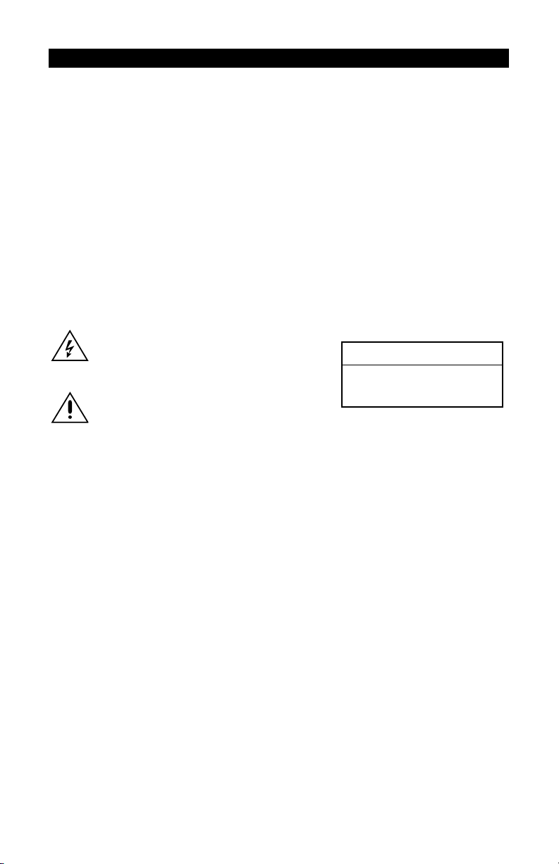
STEP 1: CONNECTING A CAMERA OR MONITOR
A
LARM
A
V
IDEO1VIDEO2
75 HM N
OO
A
UDIO
V
V
IDEO3
IDEO4
I
N
O
UT
I
NPUTS
51234
GND GND
LARM
O
UTPUTS
C
1234
OM
RS232/422/485 10/100 BASE-T
P
OWER
12V~0.8A
+5V
++++
TRANSMITTER
T
RANSP.DATA
H
ANDSET
RECEIVER
V
IDEO-
A
UDIO-
OUT
OUT
Key:
1=Cameras or other video sources with composite PAL or NTSC output
2=Video monitor with composite PAL or NTSC input
3=NET104A transmitter
4=NET101R/RA Receiver
Figure 3. Connecting Cameras Or Monitor
•To connect the cameras, plug one end of a standard coaxial cable into a BNC connector (start
with video 1) on the rear of the NET104A and the other end into the camera. You can use any
video source with a composite PAL or NTSC output.
• Set the DIP switches on the NET104A to position 75 OHM ON (down) to terminate the inputs
when the video signal is not connected to additional video equipment through a T-connection.
•To connect a monitor to the NET101R/R-A receiver, plug one end of a standard coaxial cable
into the BNC connector on the NET101R/R-A and the other end into the monitor. You can use
any PAL or NTSC video monitor with a composite PAL or NTSC input.
For more information about video sources and monitors, see the
16 C2900M-B (1/03)
Hardware Installation
section.
Page 17
STEP 2: CONNECTING ADDITIONAL ITEMS
Connect any additional items, such as alarms, audio, etc.
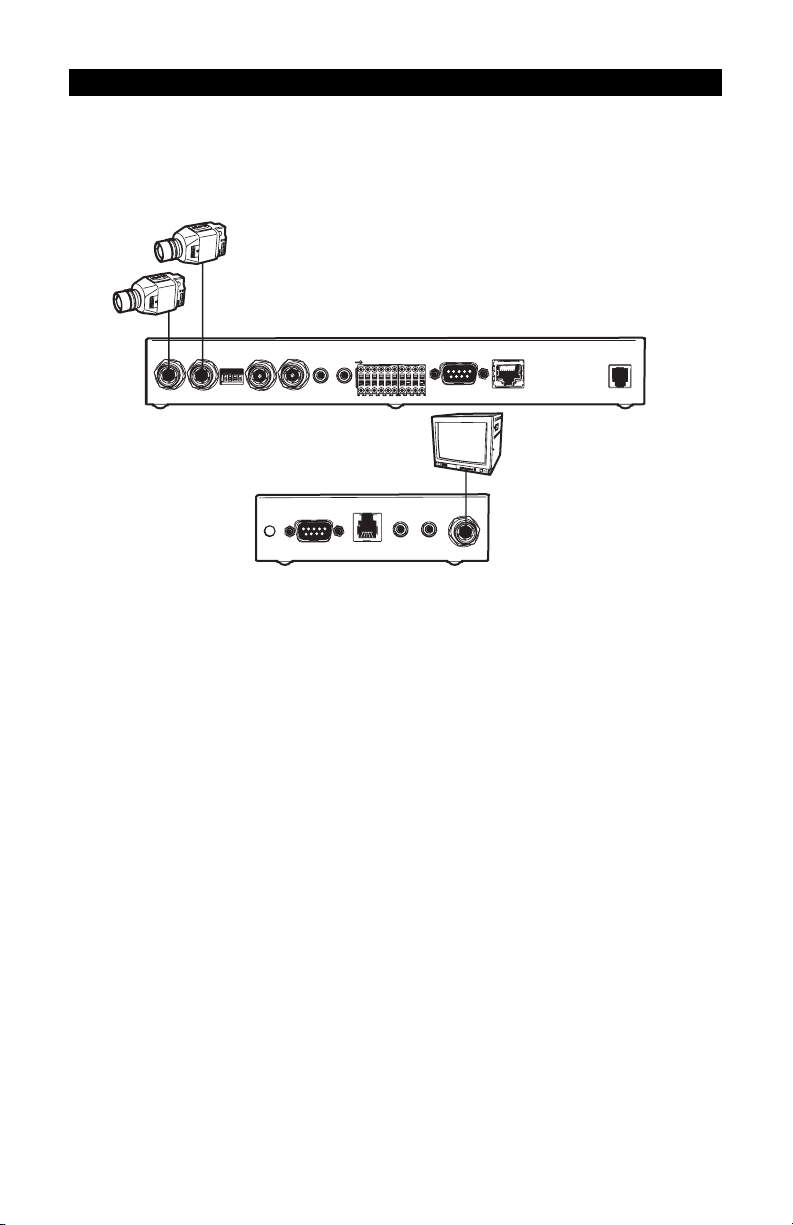
STEP 3: CONNECTING TO THE LAN PORT
A
LARM
A
I
NPUTS
51234
GND GND
LARM
O
UTPUTS
C
1234
OM
RS232/422/485 10/100 BASE-T
P
OWER
12V~0.8A
+5V
++++
A
UDIO
OO
V
V
IDEO3
IDEO4
I
N
O
UT
V
IDEO1VIDEO2
75 HM N
Key:
1=Ethernet (10BASE-T) LAN connection to hubs, network, PCs (RJ-45 connector)
2=Ethernet Cat5 cable
3=Transmitter
Figure 4. Connecting To The LAN Port
To connect to the Ethernet network, use a standard UTP Cat5 cable with RJ-45 connectors. Plug
one end of the cable into the RJ-45 receptacle labeled “Ethernet.” The connection to a 10BASE-T
network can be made directly via a hub or switch.
C2900M-B (1/03) 17
Page 18
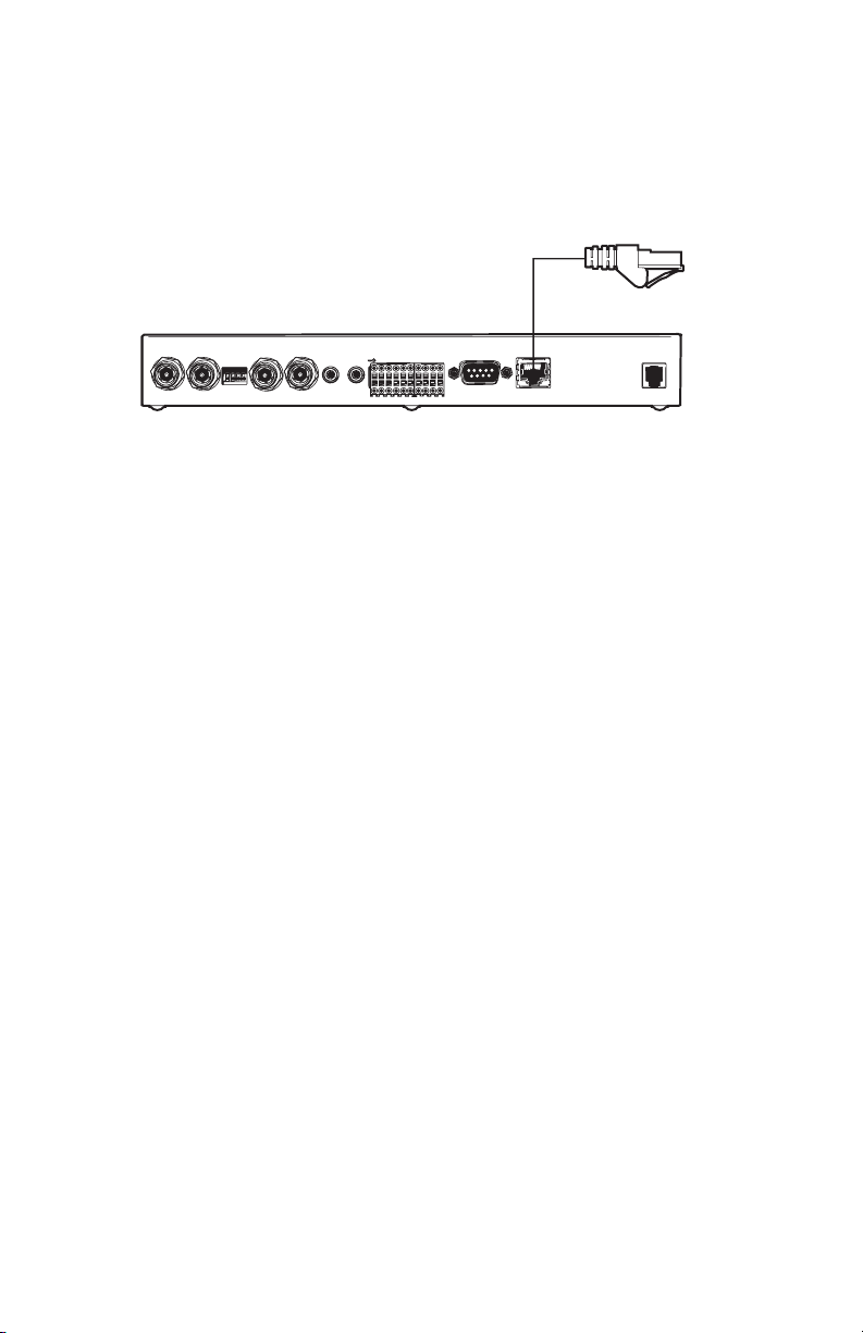
STEP 4: CONNECTING POWER
A
LARM
A
I
NPUTS
51234
GND GND
LARM
O
UTPUTS
C
1234
OM
RS232/422/485 10/100 BASE-T
P
OWER
12V~0.8A
+5V
++++
A
UDIO
OO
V
V
IDEO3
IDEO4
I
N
O
UT
V
IDEO1VIDEO2
75 HM N
Key:
1=Transmitter
2=AC power plug adapter
Figure 5. Connecting Power
The transmitter and receiver have no main power switch. Insert the power cable plug into the
power jack on the unit until it latches. Plug the other end into the wall socket.
The green POWER LED on the front of the unit lights up, showing the unit is ready for operation.
When the network is connected properly, the green ETHERNET LED lights.
18 C2900M-B (1/03)
Page 19

STEP 5: SELECTING AN IP ADDRESS FOR YOUR NETWORK
NOTE: Consult your network administrator for a valid IP address.
The NET104A comes with the default address 192.168.0.1. while a NET101R/R-A receiver’s default
address is 192.168.0.2. Before operating the system inside your own network, you need to set a
valid IP address.
Use a terminal program attached at the RS-232 control terminal port to change the IP address.
Refer to the
configuration using a terminal program.
Configuration Using A Terminal Program
section for a description of IP address
STEP 6: USING A PC’S WEB BROWSER TO CONFIGURE THE NETWORK
Configure the network using a web browser. Start your web browser and connect to the URL http://
IP-Address, where IP-Address is the IP address of the unit you want to configure. Use the
standard dot-separated format (x.x.x.x.) to enter the address.
Refer to the
Configuration Using A Web Browser
section for detailed configuration instructions.
STEP 7: WHAT IS NEXT?
The system essentially is ready to use at this point. What you do now is up to you. For example,
you can connect to the web browser to watch one or more camera views or configure additional
options (alarms, default gateways, etc.) on the configuration pages.
C2900M-B (1/03) 19
Page 20

TYPICAL APPLICATIONS
DISPLAYING REMOTE VIDEO ON A WEB BROWSER
The NET104A transmitter uses Motion-JPEG video compression or high performance H.323 coding
for transmitting across the network. This enables transmission to standard web browsers of either
live video (Live Video mode) or a stream of still images (Server Push mode).
•To activate the Live Video feature, click Live Video above the video window on the PelcoNet
NET104A Transmission System home page (see Figure 6). The unit transmits using the H.323
coding format for display in the browser.
To stop Live Video, click any other option at the top of the page.
•To activate the Server Push feature, click Server Push above the video window on the home
page. The unit continuously grabs snapshots to be JPEG encoded, transferred, and displayed
continuously by the browser.
To stop Server Push, click any other option at the top of the page.
The PelcoNet NET104A Transmission System can display live video to an infinite number of users
at a time (multicasting) or up to five users at a time (multi-unicasting). A sixth user connecting to
the same transmitter in a multi-unicast configuration cannot receive live video. In a unicast
configuration, only one user at a time can receive live video.
Server Push can support multiple users simultaneously on the same transmitter. Image quality is
good with an update rate of one image about every 2 to 10 seconds depending on the number of
users and available bandwidth.
Browsers that do not support live video technology can display an updated still image or a stream
of images in Server Push mode.
20 C2900M-B (1/03)
Page 21

Figure 6. PelcoNet NET104A Home Page
C2900M-B (1/03) 21
Page 22
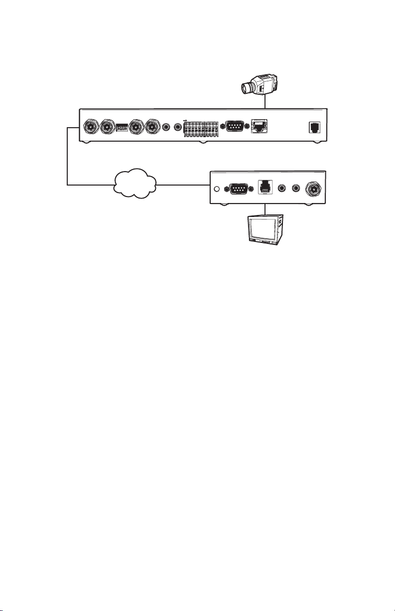
DISPLAYING VIDEO VIA A TRANSMITTER-TO-RECEIVER CONNECTION
CAMERA
A
LARM
A
V
IDEO1VIDEO2
OO
75 HM N
A
UDIO
V
V
IDEO3
IDEO4
I
N
O
UT
I
NPUTS
51234
GND GND
LARM
O
UTPUTS
C
1234
OM
RS232/422/485 10/100 BASE-T
P
OWER
12V~0.8A
+5V
++++
RECEIVER
TRANSMITTER
V
IDEO-
LAN/WAN
TCP/IP
INTRANET/INTERNET
T
RANSP.DATA
H
ANDSET
A
UDIO-
IN
OUT
MONITOR
Figure 7. Configuration For Box-To-Box Connections
There are two ways to make a high performance multimedia transmission system for computer
networks:
• One way is to use just the NET104A transmitter and connect it through the computer network
to a PC with a web browser at the receiving end.
• Another way is to connect the NET104A transmitter through the computer network to a
NET101R/R-A receiver. This is often called a box-to-box connection because it uses two
PelcoNet units.
In either case, routing dedicated cables from a camera to a monitor is not required because you can
use the existing computer network for that purpose.
22 C2900M-B (1/03)
Page 23

The following explains a box-to-box connection.
1. First, transmitter (NET104A) and receiver (NET101R/R-A) need to be configured appropriately. If
the units are supposed to be operated in different subnets, a gateway IP address must be
configured. Use the alarm IP address field to address the destination. Also, the transmitter’s
video standard must be set to H.261. Enter the settings using either a terminal program or a
web browser.
You also must disable Internet proxy settings. To do so: In Internet Explorer, click the Tools
button, Internet Options, the Connections tab, and the LAN Settings button. Then remove
the check mark in the Use a proxy server box. Click OK, and then OK again.
2. Once all addresses are configured, type c in the terminal window to establish the actual
connection or program the live video receive IP and enable the live auto connect setting
through the web browser. Make sure the alarm IP address in the unit that will initiate the
connection points to the destination unit. After a few seconds, video transmission begins and
the camera scene appears on the monitor attached to the receiver.
Instead of using a terminal program for establishing a connection, you can attach a contact to
the alarm input. Make sure the alarm input is enabled.
You can use a web browser to connect to either of the two units, even during an active box-to-box
connection. This way you can make changes to the configuration and immediately see the result of
the setting (for example, when changing video quality). If you are connected to the transmitter, the
camera pictures are sent to the receiver and web browser simultaneously. There will be a short
break in the video display on the receiver monitor whenever the web browser requests a new
frame. This is especially noticeable with the Server Push feature.
Full-duplex audio can be transmitted in parallel with the video transmission in units equipped to
handle audio. To do so, you need to use the web browser to enable audio on the Audio Settings
configuration page.
Transparent data is always transmitted automatically between the two units as soon as the
connection becomes active. Data bytes entering the interface are transported to the other end
transparently. There is no flow control mechanism for the data channel. Overflowing the serial
interface will cause data loss.
To sever the connection from either end, type d in the respective terminal window (or disable the
alarm).
C2900M-B (1/03) 23
Page 24
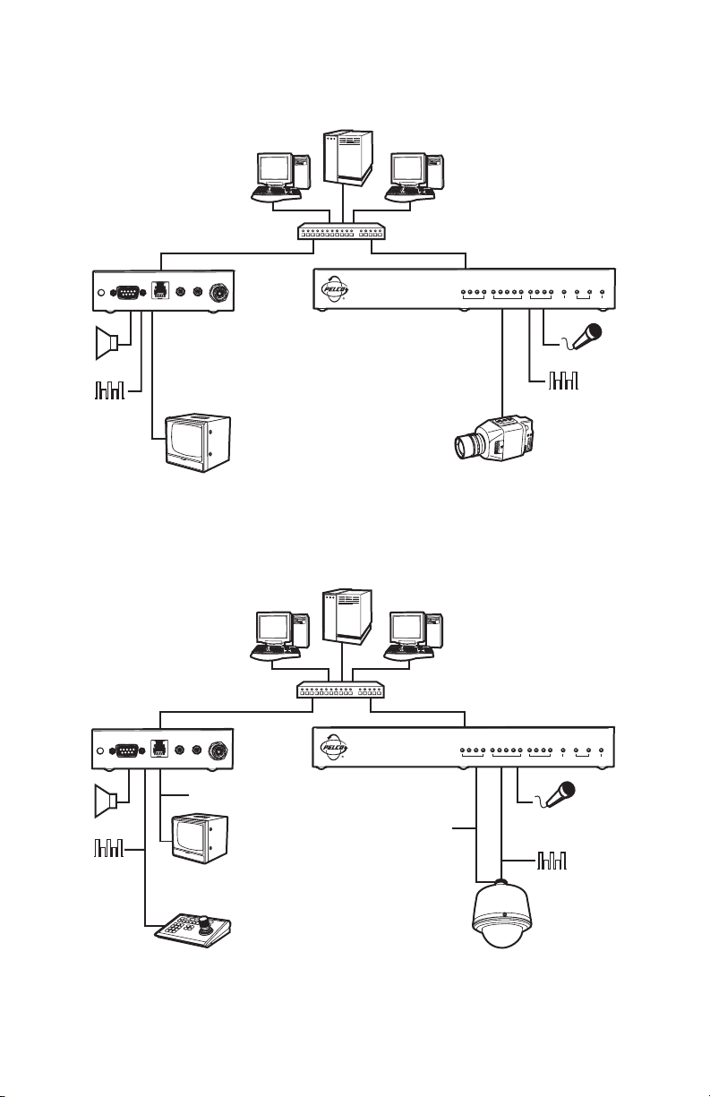
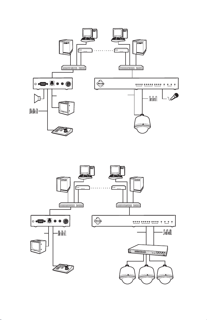
DIAGRAMS OF TYPICAL APPLICATIONS
A
A
SERVER
UDIO
DATA
RECEIVER
HUB
V
IDEO-
A
UDIO-
OUT
MONITOR
IN
NET104A
VIDEO INPUTS OUTPUTS COM ETHERNET POWER
CAMERA
H
ANDSET
T
RANSP.DATA
TRANSMITTER
AUDIO
DATA
Figure 8. LAN Box-To-Box Connection (Transmitter, Receiver, Fixed Camera)
SERVER
RECEIVER
HUB
V
IDEO-
H
ANDSET
T
RANSP.DATA
IN
A
UDIO-
OUT
NET104A
VIDEO INPUTS OUTPUTS COM ETHERNET POWER
TRANSMITTER
VIDEO
UDIO
DATA
MONITOR
KEYBOARD
VIDEO
SPECTRA
AUDIO
DATA
Figure 9. LAN Box-To-Box Connection (Transmitter, Receiver, Spectra)
24 C2900M-B (1/03)
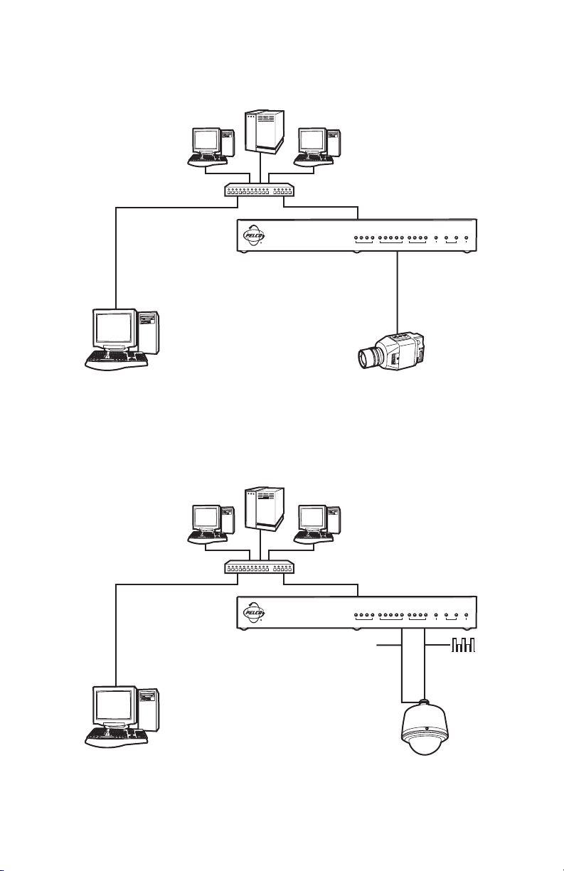
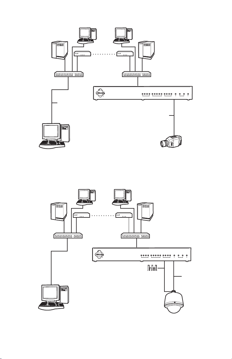
Page 25
SERVER
BROWSER
HUB
NET104A
VIDEO INPUTS OUTPUTS COM ETHERNET POWER
TRANSMITTER
CAMERA
Figure 10. LAN Browser-To-Box Connection (Transmitter, Browser, Fixed Camera)
SERVER
HUB
TRANSMITTER
NET104A
VIDEO INPUTS OUTPUTS COM ETHERNET POWER
VIDEO
DATA
BROWSER
SPECTRA
Figure 11. LAN Browser-To-Box Connection (Transmitter, Browser, Spectra)
C2900M-B (1/03) 25
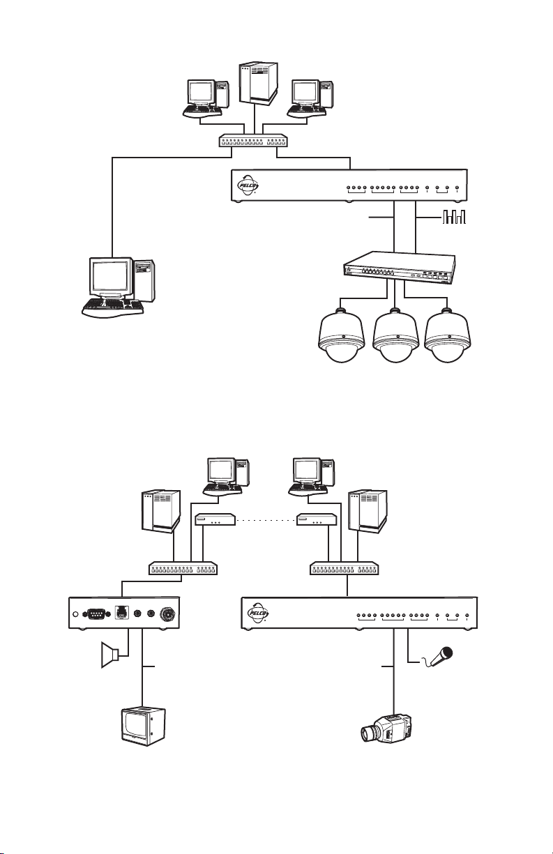
Page 26
SERVER
HUB
NET104A
VIDEO INPUTS OUTPUTS COM ETHERNET POWER
TRANSMITTER
VIDEO
DATA
GENEX
BROWSER
SPECTRA
Figure 12. LAN Browser-To-Box Connection (Transmitter, Browser, Spectra, Genex®)
1 OR MORE PCs
NEW YORK
SERVER
CLOVIS
SERVER
1 OR MORE PCs
ROUTER ROUTER
HUB
TRANSMITTER
VIDEO INPUTS OUTPUTS COM ETHERNET POWER
VIDEO
AUDIO
CAMERA
T
RANSP.DATA
AUDIO
RECEIVER
H
ANDSET
A
UDIO-
MONITOR
OUT
V
IDEO-
IN
VIDEO
HUB
NET104A
Figure 13. WAN Box-To-Box Connection (Transmitter, Receiver, Fixed Camera)
26 C2900M-B (1/03)
Page 27
CLOVIS
SERVER
1 OR MORE PCs
ROUTER ROUTER
1 OR MORE PCs
NEW YORK
SERVER
HUB
VIDEO
TRANSMITTER
VIDEO INPUTS OUTPUTS COM ETHERNET POWER
DATA
SPECTRA
AUDIO
DATA
RECEIVER
H
ANDSET
A
UDIO-
T
RANSP.DATA
OUT
HUB
V
IDEO-
IN
NET104A
VIDEO
MONITOR
KEYBOARD
Figure 14. WAN Box-To-Box Connection (Transmitter, Receiver, Spectra)
1 OR MORE PCs
NET104A
HUB
NEW YORK
SERVER
VIDEO INPUTS OUTPUTS COM ETHERNET POWER
VIDEO
TRANSMITTER
T
RANSP.DATA
VIDEO
H
ANDSET
CLOVIS
SERVER
RECEIVER
V
IDEO-
A
UDIO-
OUT
DATA
1 OR MORE PCs
ROUTER ROUTER
HUB
IN
AUDIO
DATA
MONITOR
GENEX
KEYBOARD
SPECTRA
Figure 15. WAN Box-To-Box Connection (Transmitter, Receiver, Spectra, Genex)
C2900M-B (1/03) 27
Page 28
1 OR MORE PCs
1 OR MORE PCs
CLOVIS
SERVER
NEW YORK
SERVER
ROUTER ROUTER
HUB
HUB
TRANSMITTER
NET104A
VIDEO INPUTS OUTPUTS COM ETHERNET POWER
VIDEO
VIDEO
BROWSER
CAMERA
Figure 16. WAN Browser-To-Box Connection (Transmitter, Browser, Fixed Camera)
1 OR MORE PCs
NEW YORK
SERVER
CLOVIS
SERVER
1 OR MORE PCs
ROUTER ROUTER
HUB
HUB
TRANSMITTER
NET104A
BROWSER
VIDEO INPUTS OUTPUTS COM ETHERNET POWER
DATA
VIDEO
SPECTRA
Figure 17. WAN Browser-To-Box Connection (Transmitter, Browser, Spectra)
28 C2900M-B (1/03)
Page 29

1 OR MORE PCs
1 OR MORE PCs
CLOVIS
SERVER
NEW YORK
SERVER
ROUTER ROUTER
HUB
HUB
TRANSMITTER
NET104A
VIDEO INPUTS OUTPUTS COM ETHERNET POWER
VIDEO
DATA
GENEX
BROWSER
SPECTRA
Figure 18. WAN Browser-To-Box Connection (Transmitter, Browser, Spectra, Genex)
C2900M-B (1/03) 29
Page 30

HARDWARE INSTALLATION
Refer to
Appendix A – Connecting PelcoNet NET104A To Different Components
show various connections.
CONNECTING VIDEO SOURCES OR DISPLAYS
Up to four video sources can be connected to the NET104A.
1. To connect cameras, plug a standard coaxial cable into a BNC connector (start with video 1) on
the rear of the NET104A and the other end into the camera. You can use any video source (for
example, a VCR) with a composite PAL or NTSC output. The inputs accept color or black and
white sources and automatically detect whether they are PAL or NTSC. The video inputs have
an internal termination of 75 ohms.
2. Set the DIP switches to position 75 OHM ON (down) to terminate the inputs when the video
signal is not connected to additional video equipment through a T-connection.
CONNECTING AUDIO EQUIPMENT
The NET104A provides an audio channel via the audio in and out jacks.
1. Connect the microphone to the AUDIO IN jack.
2. Connect the loudspeaker to the AUDIO OUT jack. (This is not required if you are using the
speakers on your PC.)
The audio signals are transmitted bi-directionally and simultaneously with the video signals. This
allows control of a loud speaker or door intercom system, for example, at the monitored location.
for diagrams that
30 C2900M-B (1/03)
Page 31

CONNECTING DATA TERMINALS
The NET104A has a serial interface that can be configured on the Interface Settings configuration
page for terminal control or transparent data: RS-232 or RS-485, etc.
Use As Control Terminal Port
For local control and configuration of the unit, you can connect a data terminal (for example, a PC
running a standard terminal program) to the serial interface labeled COM on the NET104A. The
9-pin D-sub connector can be connected to a PC’s COM port.
You can use a standard terminal program to communicate with the unit. The default parameters are
set to 19200 baud, 8 bits of data, 1 stop bit, and no parity (8N1).
To access the online help, type ? (a question mark) in the terminal window. For more information on
the command set, see the
send serial data that requires flow control.
You can configure the RS-485 half-duplex mode in the web browser. The RTS and CTS signals are
enabled for flow control.
If this RS-485 mode is chosen, the camera control data is transferred to this port. Certain cameras
with fixed data length require the buffered RS-485 mode. (This half-duplex mode is not required for
interfacing to any Pelco product.)
VIEWED FROM SOLDERING
Configuration
SIDE OF PLUG
1 2 3 4 5
6 7 8 9
section. This mode allows the control port to be used to
Pin Name Direction Description
1 DCD Input Data Carrier Detect
2 RXD Input Receive Data
3 TXD Output Transmit Data
4 DTR Output Data Terminal Ready
5 GND Ground
6 DSR Input Data Det Ready
7 RTS Output Ready To Send
8 CTS Input Clear To Send
9– – –
Figure 19. Control Terminal Port Pin Assignments in RS-232 Mode
C2900M-B (1/03) 31
Page 32

Use As Transparent Data Port
The serial interface offers a transparent serial data channel between the receiver and the
transmitter. A typical application for transparent data is remote control of peripheral equipment (for
example, a dome system with PTZ functions). You also can use this channel to control remotely any
external device with a serial interface. The serial data is transferred in parallel to the video and
audio data.
Transmission of transparent data is enabled only after a video connection has been established.
Also, the RS-232 interface for the transparent data port does not support hardware flow control.
For proper operation, you must configure the following in a way that they fit the associated unit:
baud rate, parity of the interface of the PelcoNet NET104A Transmission System unit, and number
of data and stop bits. Use a web browser to configure these parameters at the unit with the
configuration side.
The transparent data interface is used to control PTZ cameras remotely, to transmit data transparently between two units, or to control equipment connected to a PC COM port. Transmission of
transparent data is possible only when the units are connected. Only the data transmitting signals
are provided at this port.
Pin Name Direction Description
VIEWED FROM SOLDERING
SIDE OF PLUG
1 2 3 4 5
6 7 8 9
1– N.C.
2 RXD Input Receive Data
3 TXD Output Transmit Data
4– N.C.
5 GND Ground
6– N.C.
7– N.C.
8– N.C.
9– N.C.
Figure 20. Data Port Pin Assignments In RS-232 Mode
32 C2900M-B (1/03)
Page 33

CONNECTING EXTERNAL SENSORS
A
The unit has four alarm inputs that let you connect external signaling devices, like door contacts or
motion detectors. If configured accordingly, an alarm trigger can, for example, set up an automatic
connection between NET104A and the remote station. You can connect switches or contacts
directly without a separate power supply.
Connection INPUT 5 is a master alarm. This connection lets you activate or bar (for example, by
means of a key-operated switch) all the alarm triggers.
NOTE: Do not connect the ground terminals to earth ground. External switching voltage must not
exceed 12 VDC.
The four alarm inputs are optically isolated from the other components of the NET104A via
optocouplers and require a voltage of 5-12 VDC for switching.
Do the following to connect external sensors. Refer to Figure 21.
NET 104A
P
OWER
12V~0.8A
V
IDEO1VIDEO2
OO
75 HM N
A
LARM
A
I
NPUTS
51234
GND GND
LARM
O
UTPUTS
C
1234
OM
RS232/422/485 10/100 BASE-T
+5V
++++
A
V
IDEO3
UDIO
IDEO4
V
I
N
O
UT
CTIVE
HIGH
+5V
O
UT
A
LARM
I
NPUTS
51234
GND
++++
+5V
GND
A
LARM
O
UTPUTS
1234
ACTIVE
LOW
+5V
Figure 21. Alarm Connections
1. Pull the terminal block INPUTS from its plug-in base.
2. Attach the conductors to the alarm input and ground terminals. (Push a small screwdriver or
similar instrument into the square opening. This opens the circular opening. Insert the wire into
the circular opening, and then remove the screwdriver.)
3. Push the terminal block back on to the plug-in base.
C2900M-B (1/03) 33
Page 34

CONTROLLING PERIPHERAL DEVICES
The NET104A has four relay outputs for switching external devices (for example, lights or sirens).
The relays can be operated interactively, during an active connection, or automatically to coincide
with certain events. Settings for the relay must be configured (see the
Typical applications of the relay outputs are activating electric door openers or switching of lights
and other electrical devices. Do not exceed the maximum rating of 24V and 0.8A.
Do the following to connect peripheral devices. Refer to Figure 2.
1. Pull the terminal block OUTPUTS from its plug-in base.
2. Attach the conductors to the pairs of relay terminals.
3. Push the terminal block back on to the plug-in base.
Configuration
section).
CONNECTING TO A LAN
To connect to a 10BASE-T network, plug a standard UTP/Cat5 cable with RJ-45 connectors into the
receptacle labeled ETHERNET on the NET104A. You can connect directly to the Ethernet network.
The green Ethernet LED on the front of the unit (refer to Figure 1) lights as soon as the connection
to the network is correct physically and synchronized with the LAN. Check the cable or see the
Troubleshooting
The second Ethernet LED flashes yellow when data packages are transmitted.
section if the LED does not light.
CONFIGURATION
There are two ways to configure your system:
• The most basic control and configuration is accomplished by connecting a terminal to the
RS-232 terminal port.
•A more convenient, complete configuration and display of video is through the built-in HTTP
server, which connects to any standard web browser. This is the recommended method.
CONFIGURATION USING A TERMINAL PROGRAM
Using a terminal program (for example, the Windows application HyperTerminal) connected to the
RS-232 terminal port on the unit’s rear panel provides limited configuration and control capabilities
(null modem cable required). Ensure that the PC’s COM port is set up properly (default parameters
are 19200 baud, 8N1) and that the local terminal echo is disabled.
All commands consist of single characters you type inside the terminal window. Enter only one
command at a time and do not terminate this input by pressing the Enter key. After entering a value
(for example, an IP address), check the entered characters again and only then press Enter to
transmit the values to the NET104A.
Do the following:
1. First, disconnect the NET104A from the network.
2. Connect the D-sub COM jack on the NET104A to a free serial port on the PC.
3. Click the Start button on your PC’s desktop, and then select Programs from the Start menu.
4. Highlight Accessories. Click HyperTerminal.
5. Double-click Hypertrm.exe to open HyperTerminal.
6. Type the name for the new connection in the Name field. Click OK.
34 C2900M-B (1/03)
Page 35

7. Change the Connect using field to the COM port of the computer to which you have
connected the serial cable. Click OK.
8. Change the Bits per second field to 19200.
9. Change the Flow control field to None. Click OK.
10. Hold the Shift key and press the ? key to bring up the Help menu.
11. Press the I key to set the IP address. Type the new IP address PelcoNet will be using on the
network. Press ENTER.
12. Press the S key to set the subnet mask. Type the new subnet mask. Press ENTER.
13. Press the G key to set the gateway IP address. Type the new gateway IP address. Press ENTER.
14. Close HyperTerminal. If prompted to save settings, click OK.
The following section shows a typical terminal session.
Typical Session
The help screen appears as follows in the terminal window:
* * * * * * * * * * * * * * * * * * * * *
Help menu
? this site
i set the IP address
s set the subnet mask
g set the gateway IP address
a set the alarm IP
c connect to alarm IP
d disconnect from alarm IP
D disconnect all connections
m display MAC address
v display version information
b display current transmission data rate
t toggle DHCP on/off
disable ‘local echo’ for a better display!
* * * * * * * * * * * * * * * * * * * * *
NOTE: You cannot use backspace during a terminal session—if you mistype a character, end your
entry by pressing Enter and try again. If you see duplicate characters on any entry, the “local echo”
feature of your PC’s terminal program is not disabled.
If you are using the terminal to set up the unit’s IP address, just type i and you are prompted to
enter a new IP address:
i
->Enter new IP address (old:192.168.0.1): 192.168.0.5 (Enter)
->IP address set to 192.168.0.5
If you want to establish a live video connection to a remote unit, you have to specify the remote IP
address by typing a and entering the remote IP address in the same manner as the unit IP address
as shown in the example above.
To establish a connection, type c; to disconnect, type d.
C2900M-B (1/03) 35
Page 36

Command Reference
The following table gives an overview of all available commands. (Enter the appropriate information where indicated by the quotation marks below. Do not enter the quotation marks.)
Table A. Terminal Command Reference
Cmd Description
? Displays the help screen.
i Set up a new IP address.
-> Enter new IP address (old:192.168.152.160): ‘new
IP address’ [Enter]
-> IP address set to <new IP address>
s Set up a new subnet mask.
-> Enter new subnet mask (old:255.255.255.0): ‘new
subnet mask’ [Enter]
-> subnet mask set to <new subnet mask>
g Set up a new gateway IP address.
-> Enter new gateway IP address (old:192.168.0.10):
‘new gateway IP address’ [Enter]
-> gateway IP address set to <new gateway IP address>
a Set up a new alarm IP to connect to.
-> Enter new alarm IP address (old:192.168.0.3): ‘new
alarm IP address’ [Enter]
-> Alarm IP address set to <new alarm IP address>
c Connects a live video to the specified alarm IP.
-> connecting . . . PelcoNet tries to call the alarm IP host
connected PelcoNet has established the connection
d Disconnects any pending video connection.
-> disconnecting . . . PelcoNet disconnects
disconnected PelcoNet has disconnected
36 C2900M-B (1/03)
Page 37

D Closes the connection from the connecting IP address.
-> Close connection from <IP address>
m Display the unit’s MAC address.
-> MAC address: <unit’s MAC address>
v Display version information.
-> HW version: <version number> SW version: <version
number>
b Displays the current transmission data rate. The display is updated continuously.
tToggles the DHCP (Dynamic Host Configuration Protocol) on/off.
-> DHCP on
-> DHCP started
-> DHCP BOUND <IP address, subnet, gateway>
or
-> DHCP off
C2900M-B (1/03) 37
Page 38

CONFIGURATION USING A WEB BROWSER
In addition to the aforementioned configuration using a terminal program, which only covers the
most basic settings, a web browser is the tool of choice for a more complete configuration. To
accomplish this, the system features a complete HTTP server.
Microsoft Internet Explorer 5.5 is the recommended browser.
Web Server Concept
1. Start your web browser.
2. Connect to the URL http://IP-Address, where IP-Address is the IP address of the unit you want
to configure. Use the standard dot-separated format (x.x.x.x.) to enter the address. The home
page is displayed with the video from input 1 being shown.
The HTTP server provides six separate pages for configuration.
You can return to the home page from any other page by clicking on the PelcoNet logo on the left
side. Clicking the Pelco® logo while on the home page immediately transfers you to the Pelco
Internet home page, provided the network allows for Internet access.
In order for live video images to be decoded, the special ActiveX control file must be installed on
your PC. The latest version of ActiveX comes on the PelcoNet CD.
NET-Manager
NET-Manager is a program that can make it easier to configure PelcoNet units in local networks.
The program and manual (C2901M) are on the resource CD that comes with your PelcoNet unit.
Refer to the manual for instructions.
38 C2900M-B (1/03)
Page 39

Quick Guide To The Menu Structure
LIVE VIDEO**
SERVER PUSH**
HOME**
CONTROL**
SETUP**
*=CONTROLLED BY SERVICE PASSWORD
** = CONTROLL ED BYUSER PASSWORD
MATRIX CONTROL**
WITH
LIVE VIDEO
MATRIX CONTROL*
WITH
SERVER PUSH
GENEX MUX**
WITH
LIVE VIDEO
GENEX MUX**
WITH
SERVER PUSH
SPECTRA DOME**
SYSTEM WITH
LIVE VIDEO
SPECTRA DOME**
SYSTEM WITH
SERVER PUSH
ESPRIT **
WITH
LIVE VIDEO
ESPRIT**
WITH
SERVER PUSH
*
GENERAL
Name
ID
Password level
Password
Date
T
ime
Time zone
Time server IP
Hardware
Software
Firmware update
Configuration download
Configuration uploa
IP address
*
Subnet mask
Gateway IP address
DHCP
Base Port
Mail server IP address
Mail reply address
Multicast Group IP
Time to live (Multicast)
Enable Multilink H.323
Enable Multicast Streaming
Multicast Video port
V
ideo quality
Video standard
V
ideo resolution
Video Priority
Video bandwidth ActiveX
Network Interface bandwidth
Camera 1 - 4 name
Name stamping
Time stampi ng
Time
JPEG Size
JPEG File name
FTP
Login name
Password
Path
Input level
Outputlevel
Coding mode
Video
Motion alarm
Alarm
Master Alarm input pin
Camera Follows alarm input
Alarm status
Connect
Live
Live video auto connect
Send
Idle state
Operating mode
Relay follows
Relay Names
Trigg er Relay
Com ports
Baudrate
Data bits
Parity
Stop bits
RS232/485
Halfduplex mode
NETWORK
*
VIDEO
slice
server IP address
*
AUDIO
*
ALARM
alarm
input pin 1 - 4
video receive IP
email
INTERFACE
d
*
*
00944
Figure 22. PelcoNet NET104A Menu Tree
C2900M-B (1/03) 39
Page 40

PelcoNet NET104A Home Page
Figure 23. PelcoNet Home Page
The home page is the starting point for any configuration.
The window in the center of the screen is the display area for decoded video.
• Clicking the Pelco logo on any page connects you to the Pelco Internet home page (provided the
LAN supports Internet access).
• Click Live Video to choose a live display or Server Push for periodically updated stills.
•· Click Control to access an options screen with links to pages where you can see and control
the displayed view. (Refer to the
• Click Setup to access an options screen with links to configuration pages. Click any icon on the
side to transfer to the desired page.
40 C2900M-B (1/03)
Web Browser Control Pages
section.)
Page 41

Figure 24. PelcoNet NET104A Transmission System Setup Page
NOTE: When changing any configuration item in one of the following pages, make sure to change a
single item at a time. Then click the respective Set button. If more than one item needs to be changed,
execute the procedure repeatedly. If more than one item is changed without clicking the Set button in
between, only the entry associated with the clicked button is actually changed. All other entries
return to their previous settings.
All configuration items are stored in non-volatile memory so they are kept when the unit is
powered down.
Some configurations apply only to transmitters (for example, camera settings) while others apply to
receivers. Also, the settings require a receiver unit with the audio option (NET101R-A). All settings
not expressly restricted to certain models apply to all.
C2900M-B (1/03) 41
Page 42

General Configuration Page
The unit name and ID, as well as password settings, comprise the General Settings configuration
page.
All units have a real-time clock set during manufacture. However, time and date can be changed
any time; for example, when the units are operated in different time zones.
Version numbers for the hardware and the firmware are for information only. Whenever you need
technical support, have these numbers ready.
Figure 25. General Settings Configuration Page
42 C2900M-B (1/03)
Page 43

Table B. General Settings
Configuration Default Description
Item Setting
(Unit) Name none The unit Name and unit ID identify the device from a distance;
for example, in the event of an alarm call. The name helps when
there are many PelcoNet units on the network.
Enter a name (nine characters maximum) for the NET104A that
lets the device be easily identified. With appropriate configuration, the name will be displayed in the video window.
(Unit) ID none The ID serves as a machine-readable name. The ID can be read
at any time. Reading is facilitated remotely via UDP/IP, letting a
management system monitor the unit.
Password none Transmitters operate at two authorization levels: service or user.
level This field lets you set the password at either level.
At the service level, you can change all the configuration
settings. At the user level, you can operate but not configure the
device. You can have a live picture or see the configuration
settings but you cannot change them.
Password none The unit can be password-protected to prevent unauthorized
tampering with the configuration. The password needs to be
repeated correctly in the confirm box before password protection
is activated. If the device is not protected with a password, “No
password set” will be displayed.
Once password protection is enabled, you need to log in before
the configuration pages can be accessed (Figure 26).
You can only change one of the two passwords. To change the
other, you have to access this configuration page again.
NOTE: If you forget the password and cannot access the unit,
refer to the red caution sheet that came with the unit. The sheet
details procedures for resetting the unit to allow access. Your
settings will be erased.
Date n/a Enter the current date in DD/MM/YYYY format. This is the
system date, driven by the internal real-time clock. The day of
the week (first entry box) need not be entered and will be
automatically adjusted based on the given date.
Time n/a Enter the current time or click the Synchronize button to
synchronize the NET104A with your computer’s system time. The
system time is driven by the internal real-time clock.
Time zone Greenwich Use the pull-down menu to select the time zone for the current
Mean Time time.
(Continued on next page)
C2900M-B (1/03) 43
Page 44

Table B. General Settings (Continued)
Configuration Default Description
Item Setting
Time server IP 0.0.0.0 Enter the IP address of an Internet server that will supply
accurate time for your PelcoNet unit(s). Or synchronize to a piece
of equipment on your network.
Hardware n/a Read-only version number of the hardware. This contains unique
serial number, type of hardware, and revision.
Software n/a Read-only firmware version number. This is important informa-
tion should you need technical support.
Firmware n/a Enter the name of the file containing new firmware, or locate it
update using the Browse button. Then click the Upload button to
upload the firmware and install it on the system.
Configuration n/a Clicking the Download button saves the current configuration
download of the PelcoNet NET104A Transmission System to a PC file.
Configuration n/a This copies a file from a PC to the NET104A. Enter the name of
upload the file containing the configuration, or locate it using the
Browse button. Then click the Upload button to overwrite the
configuration with the configuration stored in the named file.
44 C2900M-B (1/03)
Page 45

When password protection is on, as described in Table B, the program displays the following
password screen if any attempt is made to configure the unit (that is, selecting one of the
configuration pages).
Figure 26. Screen For Entering The Password
C2900M-B (1/03) 45
Page 46

Network Settings Configuration Page
Figure 27. Network Settings Configuration Page
Network and routing information make up the Network Settings configuration page. The following
table describes the configuration items.
Table C. Network Settings
Configuration Default Setting Description
Item
IP address 192.168.0.1 Enter a unique IP address that is valid for your network.
The pre-configured default IP address allows for easy
configuration in closed environments. You can use a
crossed cable to directly connect to a PC. Also, the PC’s IP
address and subnet mask must match the default IP
address.
NOTE: Changing the IP address also affects the current
browser connection. You will have to enter the new URL to
regain connectivity to the unit.
Subnet mask 255.255.255.0 Enter a valid subnet mask for your network, if subnets are
in use.
Gateway IP none Enter the IP address of the router. This is typically used in a
WAN environment.
(Continued on next page)
46 C2900M-B (1/03)
Page 47

Table C. Network Settings (Continued)
DHCP off Dynamic Host Configuration Protocol. When set to on, the
network DHCP server automatically assigns your computer
an IP address. When set to off, you must assign it yourself.
Base Port 25000 Enter a setting to designate which TCP/IP ports PelcoNet
uses for transmission, video, audio, and control. For
example, the default setting of 25000 means PelcoNet will
use TCP ports 25000-25001 and UDP ports 25002-25011
(12 ports total) for all video and control data.
Mail server none Entry is only required if the mail-sending feature is to be
IP address used. Outgoing e-mail is sent to the mail server (SMTP
server) at this IP address.
Mail reply none Enter a name for the NET104A that lets the device be
address easily identified. This is similar to the unit identification
Name field on the General Settings configuration page.
This field identifies the device from a distance. The name
helps when there are many PelcoNet units on the network.
The recipient of the e-mail can identify the e-mail’s sender
by this entry.
Multicast 0.0.0.0 This is the Multicast IP Address. (Network hardware–
Group IP such as switches, hubs, routers, etc.–must support the
multicasting protocol, ICMP.) This field sets PelcoNet to
use the multicasting protocol, which allows more efficient
use of bandwidth. The IP range is 224.0.1.0 through
238.255.255.255.
Time To Live 1 This setting specifies how many routers an information
(Multicast) packet can go through before it expires.
Enable Off When set to On, this setting lets the PelcoNet unit support
Multilink H.323 five simultaneous live video connections.
Enable Off This setting, in conjunction with the Multicast Group IP and
Multicast Enable Multilink H.323 settings, can allow an unlimited
Streaming number of live video connections. The Enable Multilink
H.323 field, as well as this field, must both be set On for
this to work.
Multicast 60000 This setting designates the TCP/IP port PelcoNet uses for
Video port video when using the multicasting protocol.
C2900M-B (1/03) 47
Page 48

Video Settings Configuration Page
The Video Settings configuration page lets you modify all video-related parameters. Some items
apply only to transmitters while others require a receiver. The screen capture below belongs to a
transmitter.
Refer to Table D for default settings and descriptions.
Figure 28. Video Settings Configuration Page
48 C2900M-B (1/03)
Page 49

The following table details the configuration items.
Table D. Video Settings
Configuration Default Setting Description
Item
Video quality super fast You can set the quality of the video. On restricted
bandwidth channels, you need a compromise
between optimum image sharpness and quick
reproduction of movements in the image. With
increasing bandwidth, the effect of this setting
diminishes, as best quality and fast motion can be
maintained simultaneously.
With a high image refresh rate, sharpness deteriorates with increasing movement in the field of view.
If movement is expected in a small area only, you can
give preference to sharpness. The intelligent
compression process then is able to refresh the
affected areas in the image. The unchanged rest of
the image will be reproduced with optimum
sharpness.
With high bandwidths in the local network (above
200 Kb), you can work with maximum image quality
without the refresh rate suffering noticeably.
Video standard H.263 This field sets the video standard for the transmis-
sion. If you intend to do a box-to-box connection, set
this to H.261, click the Set button, and then click the
Reboot link to reboot the unit. An hour glass symbol
indicates the command is being processed. This
symbol remains on the screen (regardless of whether
or not the reboot is finished) until you click another
function. The POWER LED flashes when the reboot is
finished.
If you are not near the unit, wait at least one
minute to ensure the reboot finishes. If you click
another function before the reboot concludes, the
program responds with a retry or firewall message.
Delete the message, exit the program, and restart.
Video resolution standard (CIF) Choose medium (QCIF) or standard (CIF) video
resolution. Common Intermediate Format (CIF) is at
352 x 288 picture elements. For very restricted
channels (for example, wireless or low speed modem
transmission) it may be advantageous to switch to
medium (QCIF) resolution at 176 x 144 pixels for
decent image rates.
(Continued on next page)
C2900M-B (1/03) 49
Page 50

Table D. Video Settings (Continued)
Configuration Default Setting Description
Item
Video Priority ActiveX This field controls whether performance of the device
is optimized for MJPEG or ActiveX (H.261/H.263).
If you select MJPEG mode, a sequence of still images
(for example, a fresh image every second) is
displayed in the browser. This setting does not
require any plug-ins or ActiveX installation and may
be advisable for severely limited channels (for
example, the Internet).
PelcoNet recommends choosing ActiveX for best
video performance. This provides the best quality and
lowest data rate consumption. When you choose this
the first time, the corresponding ActiveX is downloaded automatically to your PC from the Pelco home
page.
Video bandwidth 1000 This field controls the transmitter bandwidth setting
ActiveX for live video. This value relates only to the video
transmission rate (without audio and protocol).
Receivers can log into the transmitter with a lower or
same data rate.
In streaming mode, this value indicates the data
transmission rate of the video. Select a video
transmission rate between 10 Kb/sec and 1 Mb/sec.
Network interface 1000 This field lets you adjust the maximum data rate that
bandwidth will be sent over the network.
Enter the data transmission rate in kbits per second.
Valid entries are 10 through 1000.
The value is the maximum bandwidth for the video
data. Also, transmission bandwidth is needed for
data; to control cameras, for example. Therefore, an
actual transfer value can be over or under the
adjusted value.
Camera 1-4 names n/a Enter the desired camera names (nine characters
maximum for each). Camera 1 is video 1 input. In
addition to the unit name, the camera names help the
user identify the locations or the visible scenes.
(Continued on next page)
50 C2900M-B (1/03)
Page 51

Table D. Video Settings (Continued)
Name stamping off Name Stamping is a combination of unit name and
camera name (18 characters maximum). This
identifier can be stamped on the video image.
Choose top for upper left corner or bottom for lower
left corner to display the name information inside the
video image. Choose off if you do not want the
names displayed. (Note that when Name Stamping
and Time Stamping are assigned to the same
position, Name Stamping has priority and will
partially obscure Time Stamping.)
Time stamping off Similar to name stamping, date and time information
can be stamped on the live video image at either the
upper or lower right corner. Stamping occurs at the
transmitter before the actual coding takes place.
Therefore, the name and date/time information are
an integral part of the coded and transmitted data.
Time slice 0 Enter the time interval in seconds at which single
images should be sent for storage on an FTP server.
These images can be accessed later (for example, to
reconstruct alarm events). Enter 0 if no single images
are to be stored.
JPEG Size M This field designates the size of each JPEG image
that will be posted to the FTP server for storage.
JPEG file name Overwrite When you save a snapshot to your PC’s hard disk, this
field specifies whether the file gets overwritten by
the next save, or another file is created with a higher
number (Increment), or another file is created with a
Date/Time designator. The file name’s root is always
“snap.”
FTP server 0.0.0.0 Enter the IP address of the FTP server on which the
IP address images will be stored.
Login name n/a Enter the login name used to access the FTP server.
Password n/a Enter the password used to access the FTP server.
Path n/a Enter the directory under which the images are to be
stored on the FTP server.
C2900M-B (1/03) 51
Page 52

Audio Settings Configuration Page
Audio configuration settings apply only to the NET104A transmitter and to the NET101R-A receiver.
You can set the input and output levels (from 0-100%) on this configuration page. You can use the
Coding Mode menu item to set the sending side’s coding mode.
The audio decoder automatically follows the transmitter’s selected audio coding. If the receiver
cannot decode the selected mode, an automatic fall-back to the next available audio mode occurs.
Figure 29. Audio Settings Configuration Page
52 C2900M-B (1/03)
Page 53

The table below details available configuration items.
Table E. Audio Settings
Configuration Item Default Setting Description
Input level 64% Enter the sensitivity of the audio input. You need to
adapt the input sensitivity to the level of the audio
source to avoid overdriving the signal, causing
distortion. Experiment for the best setting.
Output level 32% Enter the sensitivity of the audio output. Adapt the
output level to the requirements of connected
audio equipment.
Coding mode off Select the coding mode for audio data. Mode
G.711 supports all systems. Pick G.711 or off to
work without coding.
C2900M-B (1/03) 53
Page 54

Alarm Settings Configuration Page
The PelcoNet NET104A Transmission System is not only a multimedia gateway but also a security
device and, therefore, has many features related to security applications. The Alarm Settings
configuration page lets you configure your unit for video surveillance applications. This page
basically applies to transmitters only. However, receivers do provide the same features. In most
surveillance-related applications, the receiver is located in a secure alarm center-type environment
while the transmitter is mounted inside or at the location to be monitored. Refer to the
Applications
section for more information about remote video surveillance.
Typical
Figure 30. Alarm Settings Configuration Page
54 C2900M-B (1/03)
Page 55

The set of video surveillance features is explained below.
Table F. Alarm Settings
Configuration Default Setting Description
Item
Video alarm off If you select on, the signal from the video source (the
camera in most cases) is monitored constantly for
interruption. If no signal is received, the NET104A
triggers the alarm.
Motion alarm off The system has a video motion detection feature.
The video scene is monitored constantly for relevant
motion.
To set motion detection, do the following:
1. Select on to trigger an alarm in the event of
movement.
2. Click the Configuration button to access the Motion
Detection screen. If you want to accept the factory
settings, click the Defaults button.
3. Use the Camera input pull-down menu to select the
camera view you want motion detection on.
4. Click the Select area button to display a window with
a grid superimposed on it. Select the cells in the image
you want the system to monitor for motion. To set an
individual cell, click it with the left mouse button (it will
turn red). Click with the right button to deselect a cell
(which will turn white). Select or deselect multiple
cells by holding down the left or right mouse button
and dragging. Release when finished.
5. Use the Motion tracking pull-down menu to turn
on/off tracking.
6. The Tracker box indicates and controls the direction of
motion detection. You can set motion detection to
operate in one direction only by removing the check
marks in the opposite direction.
(Continued on next page)
C2900M-B (1/03) 55
Page 56

Table F. Alarm Settings (Continued)
Configuration Default Setting Description
Item
7. Use the Local sensitivity slide bar to set
detection sensitivity. You need to adapt sensitivity
to the respective environment and the acceptable
false alarm rate: for a lower false alarm rate
select a lower sensitivity and vice versa.
Experiment to find the best setting. Use of the
motion detection feature is recommended only
indoors and under controlled lighting conditions.
8. Use the Average n[frames] slide bar to define
for how long or over how many pictures motion in
the scene must be detected before an alarm will
be released. If the value is low, even movement
over a small period triggers an alarm. If the value
is high, movement over a longer period is
required to trigger an alarm.
9. Use the Object min size [nxn blocks] slide bar
to designate the minimum number of cells in the
frame a moving object must fill to trigger an
alarm. You can set the value between 1*1 and
6*6 (2*2 is recommended). If the size of the
object in the picture exceeds the value you set,
motion detection triggers an alarm.
10. The Alarm indicator box lets you set a
threshold so an alarm is triggered only if the
sensitivity of the video sensor is exceeded. Thus,
something such as background noise caused by
the camera can be filtered to avoid unwanted
alarms.
Pull up or down on the blue line to observe the
motion detector. Set it straight above the basic
deviation of the red curve.
11. Press Default to get the default settings for
motion detection.
The following conditions must be met for motion
detection to function:
• Motion detection must be activated.
• At least one cell must be activated.
• Sensitivity must be set higher than zero.
• The master alarm may also have to be activated.
(Continued on next page)
56 C2900M-B (1/03)
Page 57

Table F. Alarm Settings (Continued)
Alarm input off If external sensors or simple contacts or switches will
pin 1-4 be used with the system, you need to select the
alarm input.
Click on to activate alarm triggering via an external
sensor for the selected pin. Otherwise, click off.
You also can specify whether the alarm is triggered
by the voltage level active high (normally open) or
active low (normally closed).
In addition, you can enter a name (nine characters
maximum) for the selected pin in the Name field.
Master Alarm off You can use alarm input 5 as a master alarm; for
input pin example, if a key switch is used to arm the system.
If you choose on, alarm input 5 must be active to
enable all other alarms.
Camera follows off Select on to display the image of the corresponding
alarm input camera automatically when an alarm is triggered.
Choose off to keep the current camera display.
Alarm status off Current alarm activation status can be shown in the
video image (similar to the name, date, and time
stamping discussed in Table D).
If configured to be on, the status of the activated
alarms, namely, video, motion, and input, is shown in
the upper left corner of the video image. Or, the
display can be activated as soon as an alarm
condition is reached (choose on alarm). This way, the
video image corresponding to the alarm condition is
clearly marked.
Also, there is a choice to keep the status display,
once an alarm has been triggered, even when the
original cause of the alarm is no longer present
(choose hold display), or to have the status display
follow the alarm condition (choose hold off).
(Continued on next page)
C2900M-B (1/03) 57
Page 58

Table F. Alarm Settings (Continued)
Configuration Default Setting Description
Item
Connect no The alarm functions would have little effect without
automatically triggering corresponding actions. Select
yes for automatic connection to the given IP address.
The idea is to provide a remote monitoring station with
live video in case of an alarm.
This feature can be useful even for many applications
not related to alarm conditions. One example is a
video-equipped door entry system: when the doorbell
is pressed, a contact closes and the connected
transmitter autonomously connects to a receiver. Fullduplex audio can provide verbal communication, while
the relay output can open the door remotely.
On receivers, the default alarm connection IP address
is set to 192.168.0.1 (default IP of transmitter).
Live video 0.0.0.0 Enter the IP address of the transmitter or receiver to
receive IP be notified in the event of an alarm. If that remote unit
has a password, enter it in the Remote Password field
below so the two units can communicate with each
other.
Remote empty If applicable, enter the password to access a
password transmitter (refer to the Live Video Receive IP field
above).
Live video off Select on if at each restart an active connection
auto connect should be set up automatically to the IP address
defined above. Otherwise, select no.
The auto connect feature guarantees an active
connection to the given alarm IP address even after
connection breakdown or network failures. If you
select auto connect, the network cable can be pulled
at any time. As soon as the network comes back
alive, the connection is reinstated. On a receiver, this
feature is enabled to establish a connection to a
transmitter automatically.
Send email off Select on to send an alarm e-mail in the event of an
alarm. A person who does not have a video reception
device can thus be informed via an attached JPEG
image sent to the predefined e-mail address.
(Continued on next page)
58 C2900M-B (1/03)
Page 59

Table F. Alarm Settings (Continued)
Receiver email empty If applicable, enter the e-mail address where you
address want an e-mail sent in the event of an alarm.
Idle state open You can configure the switching behavior of each
built-in relay output at idle: open (N.O. at zero
current) or closed (N.C. at zero current).
Operating mode Bistable Select an operating mode for each relay.
• When you select the default Bistable mode, the
relay will stay in the idle or active state for an
indefinite period. (For example, select Bistable if
a floodlight activated by an alarm is to remain
switched on at the end of the alarm.)
• When you select Monostable mode, the relay
automatically falls back to the idle state after a
predefined period expires. (For example, select
Monostable 10s if a siren triggered by an alarm is
to sound for a period of 10 seconds.)
Relay follows None If necessary, select a particular event from the pull-
down menu that will trigger the relay. A typical
application is having the relay following the status of
the connection; for example, to power peripheral
equipment or even the camera itself. Select from the
following:
• Motion alarm: Triggering by motion alarm
• Input pin: Triggering by external alarm sensor
• Video loss: Triggering by video signal alarm
• Connection: Triggering at each connection setup
• Remote input pin: Triggering by switching
contact of the remote station
• None: No relay triggering by events
Relay Names Relay 1-4 Assign a relay name to each output.
Trigger Relay n/a Clicking the appropriate Relay button switches that
relay by hand. Typical applications are opening
remote doors or operating lights.
C2900M-B (1/03) 59
Page 60

Interface Settings Configuration Page
You can use the Interface Settings configuration page to configure the parameters of the communication ports.
Figure 31. Interface Settings Configuration Page
60 C2900M-B (1/03)
Page 61

The default parameters of the transparent data port agree with the most commonly used settings,
as shown in the following table.
Table G. Interface Settings
Configuration Default Setting Description
Item
Com ports Terminal This port can be set to Te rminal mode, which is used
to program the unit through HyperTerminal.
Or, it can be set to Transparent, which allows
control of devices such as a digital video recorder
(DVR) or pan/tilt/zoom camera, etc. When set to
Transparent PelcoNet cannot be accessed through
HyperTerminal.
Baudrate 19200 Select any transmission rate from 300 to 19200 baud.
Data bits 8 Select the number of data bits (7 or 8) per character.
Parity None Select the type of parity check (Odd, Even, or None).
Stop bits 1 Select the number of stop bits (1 or 2) per character.
RS232/485 RS232 Select the required protocol for the port.
Halfduplex mode off If you choose this RS-485 mode, camera control data
is transferred automatically to the control port, which
is a serial interface on the unit’s rear panel to which
you can connect a PC. This mode supports flow
control.
NOTE: In the “on” or “buffered” mode, transparent
data is rerouted to the control terminal port; terminal
functions are provided on the transparent data port.
C2900M-B (1/03) 61
Page 62

LIVE VIDEO AND SERVER PUSH VIDEO PAGES
The Live Video page shows a real-time picture of a camera view with update rates and image
quality similar to a box-to-box configuration. It can be configured for bandwidth use and for various
image quality settings. The Server Push page shows still pictures that are updated periodically, and
image quality is fixed.
1. To access the PelcoNet NET104A Transmission System home page, you must first connect to
the Internet/intranet network and open Internet Explorer (the browser).
2. Then, enter the default address 192.168.0.1 in the address box. If this address has been
changed, enter the application address. The home page appears.
3. Click either Live Video or Server Page on the home page.
To exit either page, click an option at the top of the page.
The program displays dialog boxes when you try to view live video under any of the following conditions:
• With a browser other than Internet Explorer
• Without first installing ActiveX (Figure 32)
• When your computer display is not set for 16- or 32-bit color
(To change: right click the desktop, and then click Properties, the Settings tab, and select
High Color [16 bit] or True Color [32 bit]. For NT, select 65536 Colors.)
• When Microsoft Virtual Machine is not enabled.
(To enable: on the Tools menu select Internet Options, select the Advanced tab, locate
Microsoft VM, checkmark Java Console Enabled and JIT compiler for virtual machine
enabled. Reboot your PC.
With any of these conditions, you can only view the video as a series of still images.
Figure 32. ActiveX Dialog Box
62 C2900M-B (1/03)
Page 63

WEB BROWSER CONTROL PAGES
ACCESSING THESE PAGES
1. To access the PelcoNet NET104A Transmission System home page, you must first connect to
the Internet/intranet network and open Internet Explorer (the browser).
2. Then, enter the default address 192.168.0.1 in the address box. If this address has been
changed, enter the application address. The home page appears.
3. Click Control to access the Device Controls page.
4. The Device Controls page has underlined links to the control pages. To access, click one.
Figure 33. Device Controls Page
C2900M-B (1/03) 63
Page 64

CONTROLLING THE DISPLAY
The live video control pages include representations of keys that let you control various functions
(in addition to showing the camera display). Use the mouse pointer and click the left mouse button
to enable options and operate controls on the screen. Click outside of the options to disable a radio
button or selection button.
Live video pages let you choose the size of the video viewing area. Click either 352x288 (small) or
704x576 (large) in the Resize Video field.
Live video pages also let you record and play back camera views on a PC’s hard drive. Refer to the
Record and Play Back the Display on a PC
On the Spectra and Esprit live video control pages, you can control the following:
• Presets – To program a preset: select the camera by clicking its button, position the camera,
click the Set check box, and click a preset number button.
To activate a preset: click the camera button and then click a preset number button.
• Patterns – You can program only one pattern per camera through PelcoNet. To program a
pattern: select the camera by clicking its button, click the Set check box, then click Start, and
then use the arrow buttons to position the camera. Click Stop to halt pattern programming.
To operate a pattern: select the camera, click Start to begin the pattern and Stop to halt.
• Programming Menus – To access the programming menus: select the camera by clicking its
button, click the Set check box, and then click the 95 button. Use the camera arrow keys to
move up/down the menus. Use the open iris icon to open menus and set options. Use the open
iris icon in conjunction with the Exit option to move backward through menu layers and to exit
programming mode.
section for details.
NOTE: If you installed Internet Explorer from the PelcoNet NET104A Transmission System CD, ActiveX
is already installed. Otherwise, you must install ActiveX before you can view the video. Refer to the
Instructions for the Network Administrator
NOTE: PTZ control always defaults to camera 1. Therefore, if you are viewing and controlling
camera 2, 3, or 4 and then exit, you will not have control of that camera when you return. You must
select again the camera you want to control.
64 C2900M-B (1/03)
section.
Page 65

MATRIX CONTROL LIVE VIDEO/SERVER PUSH PAGE CONTENTS
Figure 34. Matrix Control Page
The Matrix Control pages contain the following:
•Ten numbered buttons
• CAM (camera) button
• MON (monitor) button
• CLR (clear) button
• PRST (preset) button
•PATT (pattern) button
• MAC (macro) button
• STOP button
• BWD (backward) button
• FWD (forward) button
• PC hard drive record/playback control buttons beneath the live screen (refer to the
Play Back the Display on a PC
section for more information)
Record and
The following are arrayed under “Lens”:
• Iris open and close buttons
• Focus far and near buttons
• Zoom out and in buttons
The following are arrayed under “Pan/Tilt”:
• Eight direction arrow buttons
• Home button in the center returns the camera to its starting position (preset 1 must be set for
the button to function)
The page also contains the following:
• AUX ON button
• AUX OFF button
C2900M-B (1/03) 65
Page 66

GENEX LIVE VIDEO/SERVER PUSH PAGE CONTENTS
Figure 35. Genex Control Page
The Genex pages contain the following across the top of the page:
• Main and Spot monitor selection radio buttons
•A Live/VCR button
•A Sequence button
•A View button
•A zoom button
•A picture-in-picture button
• Buttons for 4-, 9-, and 16-screen display
The following are arrayed down the right side of the page:
• Radio buttons for 16 cameras
• Iris open and close buttons
• Focus far and near buttons
• Zoom out and in buttons
• Eight direction arrow buttons with a home button in the center
•Ten numbered buttons to use with the Pattern button (enter preset number and click Pattern)
•A Pattern button
PC hard drive record/playback control buttons are arrayed beneath the live screen (refer to the
Record and Play Back the Display on a PC
66 C2900M-B (1/03)
section for more information).
Page 67

NOTE: You may not have control of the desired camera when switching between the spot and main
monitor radio buttons.
To control a camera and view it on the spot monitor:
1. Make sure you are viewing video on the main monitor.
2. Click the radio button for the camera you want to view on the spot monitor.
3. Click the radio button for the spot monitor.
If you do not follow this procedure, you may not have control of—or be viewing—the desired
camera on the spot monitor.
The following example shows what can happen if you do not follow the procedure:
1. Select camera 16 on the main monitor.
2. Select the spot monitor. You will view and control camera 16.
3. Select the main monitor. You will view camera 16.
4. Select camera 7. You will view camera 7 on the main monitor.
5. Select the spot monitor. You will view camera 7 on the spot monitor but control camera 16. To
view camera 16, return to the main monitor and select camera 16, then select the spot monitor.
Now you can view and control camera 16. If you select another camera (for example, 8), you
can control camera 8 but not view it. Return to the main monitor, select camera 8, and then
select the spot monitor. Now you can control and view camera 8.
NOTE: The View button on this page does not function the same way as the View button on the
Genex unit. You cannot enter multiplexer setup with the PelcoNet View button. You can, however,
enter multiplexer setup with the View button on the mulitplexer unit, and then on the PelcoNet screen
you can use the arrow buttons to navigate and the iris open button to make changes.
C2900M-B (1/03) 67
Page 68

SPECTRA LIVE VIDEO/SERVER PUSH PAGE CONTENTS
Figure 36. Spectra Control Page
The Spectra pages contain the following arrayed down the left side:
• Four camera selection buttons
•A Mux button for putting the screen into quad view
The following are arrayed down the right side under “Lens”:
• Iris open and close buttons
• Focus far and near buttons
• Zoom out and in buttons
The following are arrayed under “Pan/Tilt”:
• Eight direction arrow buttons
• Home button in the center returns the camera to its starting position (preset 1 must be set for
the button to function)
The following are arrayed under “Presets”:
•Ten numbered preset buttons
•A Set check box
•A preset 95 button for entering the programming menus
The following are arrayed under “Pattern”:
•A Start pattern button
•A Stop pattern button
PC hard drive record/playback control buttons are arrayed beneath the live screen (refer to the
Record and Play Back the Display on a PC
NOTE: When returning to this page, camera radio buttons 1-4 and the Mux button always show
camera button 1 selected even if another camera is being viewed.
68 C2900M-B (1/03)
section for more information).
Page 69

ESPRIT LIVE VIDEO/SERVER PUSH PAGE CONTENTS
Figure 37. Esprit Control Page
The Esprit pages contain the following arrayed down the left side:
• Four camera selection buttons
•A Mux button for putting the screen into quad view
The following are arrayed down the right side under “Lens”:
• Iris open and close buttons
• Focus far and near buttons
• Zoom out and in buttons
The following are arrayed under “Pan/Tilt”:
• Eight direction arrow buttons
• Home button in the center returns the camera to its starting position (preset 1 must be set for
the button to function)
The following are arrayed under “Presets”:
•Ten numbered preset buttons
•A Set check box
•A preset 95 button for entering the programming menus
The following are arrayed under “Pattern”:
•A Start pattern button
•A Stop pattern button
•A Wiper button
PC hard drive record/playback control buttons are arrayed beneath the live screen (refer to the
Record and Play Back the Display on a PC
C2900M-B (1/03) 69
section for more information).
Page 70

ADVANCED FEATURES
AUTOMATIC CONNECTION FEATURE
The advantage of conventional dedicated cabling lies in guaranteed performance and availability.
The PelcoNet NET104A Transmission System’s auto-connect feature is designed to provide the
same level of guaranteed connectivity expected from analog coaxial video cables.
IT networks commonly experience short breakdowns and congestion. Protocols used for computer
communication (for example, TCP/IP) are designed to cope with missing data and interruptions.
With the PelcoNet NET104A Transmission System, once a video connection is established, the
video stream normally terminates gracefully when a network connector is pulled or the network is
otherwise disrupted.
The system can be configured to reconnect automatically to guarantee connectivity. To activate this
feature, click the Connect radio button to On (in the Alarm Settings configuration page) and
confirm this choice by clicking the Set button. Now the unit will try to connect to the specified
alarm IP address every time. The receiving station (alarm IP address) can be another receiver.
VIDEO MOTION DETECTION FEATURE
The transmitter can check video input automatically for significant motion in the scene and trigger
an alarm if the motion exceeds a preset threshold. Activate motion detection by setting Motion
Detection to on in the Alarm Settings configuration page.
Click the Configuration button to select parameters for motion detection. You need to tailor these
parameters to the particular application. Experiment to find the best settings. For example, higher
sensitivity may lead to erroneous detection and increase false alarms.
You can restrict motion detection to certain areas in the scene. Select the cells you want the
system to monitor for motion. To set an individual cell, click it with the left mouse button (the cell
will turn red). Click with the right mouse button to deselect a cell (which will turn white). Select or
deselect multiple cells by holding down the left or right mouse button and dragging. Release when
finished.
70 C2900M-B (1/03)
Page 71

ALARM NOTIFICATION BY E-MAIL
The e-mail feature lets you send an e-mail message to a recipient on any alarm event. This could
be used to signal an alarm to people who cannot be reached with a video-based notification.
To activate this feature, enable at least one of the alarm inputs, configure a receiver e-mail
address, and activate the Send Email button. Remember to configure a mail server and gateway IP
addresses on the General Settings configuration page.
Now the system will send an e-mail to the specified recipient on every alarm event. There will be a
timeout of at least 30 seconds before the same alarm event generates another e-mail message.
The e-mail will contain the status of the four alarm inputs so you can see which event triggered the
e-mail.
RECORD AND PLAY BACK THE DISPLAY ON A PC
Live video control pages let you record the camera display on a PC’s hard drive and play it back
later. The file is recorded on the hard drive of the PC on which you are viewing the picture. The
controls are a row of buttons beneath the screen.
NOTE: Audio is not saved to the AVI file. Consequently, there is no audio on playback.
– These buttons jump the display to the beginning or ending of the recording in playback
mode.
– These buttons incrementally move the display backward and forward while the display
is paused in playback mode.
– This button stops the recording or playback.
– This button pauses the recording or playback.
– This button plays the recording.
– This button starts the recording.
AVI
– This button is used to designate a location for saving the recording.
– This button is used to load a recorded file for playback.
C2900M-B (1/03) 71
Page 72

Recording The Display
Do the following to record the camera display:
1. Access a live video control page (by clicking Control on the Home page, and then clicking one
of the underlined links to a live video control page).
2. Select a camera.
3. Position the camera as desired (if it has PTZ capability).
4. Click the
button. The Choose Directory window opens.
5. Select a location in which to save the recording. Click OK.
6. Click the
7. Click the
button to begin recording.
AVI
button to halt recording. The recording is saved automatically.
Playing Back The Recording
You can play back the camera recording either through the Windows Media Player or in PelcoNet
through the browser. Do the following to play back the camera recording through the browser:
1. Access a live video control page (by clicking Control on the Home page, and then clicking one
of the underlined links to a live video control page).
2. Click the
3. Select the directory where the file you want is located. Click the file to select it, and then click
Open.
4. Click the
To advance or reverse the playback, first click the
button moves the recording a few frames. To move to the beginning or end of the recording,
click a
button. A directory window opens.
button to begin playback.
button. Each click of a or
or button. Click the button to resume playback.
5. Click the
clicking the
72 C2900M-B (1/03)
button to halt playback and return to live video. You can replay the recording by
button.
Page 73

FIRMWARE UPLOAD
Units have flash EPROMs for firmware upgrades in the field. These upgrades can be done directly
from the web browser.
Do the following to upload firmware using the web browser:
1. Obtain the latest PelcoNet NET104A Transmission System firmware from Pelco
(http://www.pelco.com).
2. Use the browser to select the General Settings configuration page of your unit.
3. Use the Browse button in the Firmware update field to select the correct new firmware file.
4. Click the Upload button.
5. After about 30 seconds you should get a feedback message from the connected unit.
6. The message “upload complete – WAIT” confirms the correct upload of the new firmware,
which is now being installed. The alarm input LEDs will flash back and forth between red and
green to indicate installation.
WARNING: Do not disconnect power to the unit for any reason while firmware is being installed. Disrupting the cycle will damage the flash EPROM. If this occurs, you will have to return
the unit for repair.
When all the alarm input LEDs turn green, reprogramming is complete and the unit cycles
power.
7. If you try to upload an invalid firmware file, you will get the message “Upload Failed.”
8. If you revisit the General Settings configuration page after the firmware is uploaded
successfully, you will see the message “New Firmware Installed.”
C2900M-B (1/03) 73
Page 74

TROUBLESHOOTING
If the following instructions fail to solve your problem, contact Pelco Technical Support at
1-800-289-9100 for help. You should have the serial number from the bottom of the unit and the
firmware version ready in case they are needed.
Do not try to personally repair a unit. Opening it immediately voids any warranty. Leave maintenance and repairs to qualified technical personnel. Swap a defective unit with a replacement unit
and return the defective one for repair.
BASIC FUNCTIONING
LEDs on the unit indicate its condition. The following sections describe malfunctions indicated by
the LEDs.
Green Power LED
Green Power LED Is Off
If the green power LED on the front panel is off and you believe it should be blinking, check the
following:
• Make sure the enclosed power supply is connected correctly to the power plug socket.
• Make sure the power supply is connected correctly to a functioning power outlet.
• Check the power cord for apparent damage.
• Check the power supply for a 5 VDC output. If it is correctly connected and the green power
LED still does not light, exchange the power supply for a new one.
Green Power LED Blinks Slowly
This does not indicate a malfunction but means a connection exists between one unit and another.
Connections with a web browser have no effect on this LED, so there will be no blinking light
during configuration.
Green Power LED Lit
This indicates the NET104A is on but there is no connection.
Green Power LED Stays Off After Firmware Upload And Reprogramming
If the power LED does not come back on after a firmware upload, there may have been a problem
during upload. Return the system to the dealer.
Closely follow the instructions for the firmware upload. Especially do not disconnect the power
supply during firmware upload and reprogramming.
74 C2900M-B (1/03)
Page 75

Ethernet LEDs
The green Ethernet LED should light when the Ethernet connection is made. If this LED is off:
Green Ethernet LED Is Off
• Make sure the network cable is firmly connected to the hub or switch.
• Does the hub or switch work correctly in the network? Check the power supply of the hub or
switch.
• Use a Cat5 straight-through cable to connect to a normal hub. Check the cable for physical
damage.
• Use a crossover cable if connecting a unit directly to a PC without a hub.
Yellow Ethernet LED Is Flashing
The yellow LED flashes briefly whenever a unit transmits a data packet (for example, when
accessing the unit with a web browser). If this LED fails to come on, perform the following checks:
• Are all units connected correctly with the power supply? Check power supplies and
connections.
• Did you configure the correct IP address for your unit?
• Is your web browser configuration correct?
• Is the TCP/IP protocol installed on your PC operating system, and is an IP address assigned to
the PC?
• Are the subnet mask and gateway properly set up?
Contact your network administrator if you have problems installing your network.
Com LED
This green LED should flash when data is transmitted via serial interface.
Output LEDs
If green LED is lit, then the alarm output is switched. If not lit, then the output is inactive (idle
state).
Input LEDs
If the LED is not lit, then the alarm input is inactive.
If the LED is lit green, then the alarm input is activated. If lit red, then the alarm is triggered.
If the LED changes from red to green, then program memory is being deleted (during firmware
upload). The programming progress is indicated by the alternating green lighting of all five LEDs.
C2900M-B (1/03) 75
Page 76

Video LEDs
When lit green, these LEDs indicate the corresponding video input is selected. (In multiplexer
mode, the LEDs change automatically in quick succession.)
TERMINAL PROGRAM
If the terminal program fails to connect to the unit’s terminal port, check the following:
• Is the right COM-port interface on the PC selected for the terminal program, and are the
settings correct? Is the cable connected to the terminal and not the data port on the unit?
Program default settings are 19200 kb/s, 8 data bits, no parity, 1 stop bit (8N1) for the terminal
program.
• If the data exchange between the terminal program and the system still does not work, check
the serial cable. Does the system answer when you enter a question mark?
• Disable the local echo if you see duplicate characters on your screen.
TROUBLESHOOTING A TCP/IP NETWORK USING A PING UTILITY
(Enter the appropriate information where indicated by the quotation marks below. Do not enter the
quotation marks.)
To see if a unit in your network can be reached, try to ping your unit by typing the following
command in a DOS window:
c:\>ping ‘unit IP address’
If it is reached, there will be a response like the following:
Reply from <IP address>: bytes=32 time=NN ms TTL=xxx
If the LAN path is malfunctioning, the ping command will time out. If so, you could have one of the
following problems:
• Wrong physical connections. Make sure the green Ethernet LED is on. See the
Functioning
•Wrong network connection. Verify the IP address is entered correctly and that subnet mask and
gateway address are set properly.
Otherwise, ask your network administrator.
76 C2900M-B (1/03)
section for more information.
Basic
Page 77

TROUBLESHOOTING CONNECTION PROBLEMS
If you fail to connect to a system from a hardware receiver, check the following to pinpoint the
problem:
• Do not connect two units of the same type (for example, receiver to receiver).
• Make sure network connectivity is available (for example, by using the ping command as
described above).
TROUBLESHOOTING THE VIDEO CONNECTION
If no video or a distorted video image is displayed at the receiver during a connection to a
transmitter:
• Make sure to use the right unit for your application: a camera can be connected only to a
transmitter, never to a receiver.
• Make sure the camera is switched on and the coaxial cable is connected to the transmitter.
• Check the camera cable and connect a video monitor to the camera to check that the camera is
functioning correctly.
• At the receiving system, make sure the monitor is switched on and the coaxial cable is
connected to the receiver.
• Check the monitor cable and the selection of the monitor channel, if the monitor features more
than one video channel.
• If the monitor can display only a single video standard (PAL or NTSC), check the setting of the
video output format on the Video Settings configuration page.
C2900M-B (1/03) 77
Page 78

TESTING THE AUDIO CONNECTION
This test procedure applies only to NET104A and NET101R-A units.
Test Between NET104A And NET101R-A
1. Connect a microphone (via a preamplifier) to the Audio In jack and a loudspeaker to the Audio
Out jack on the NET104A. Connect a microphone to the Line-In RCA jack and a loudspeaker to
the Line-Out cinch connectors on the NET101R-A.
2. Make sure the correct menu items are set on the Audio Settings configuration page of both
systems; that is, select the appropriate interface (line I/O).
3. Switch the coding mode to G.711 or G.728.
4. Select a volume above zero.
5. After establishing the Ethernet connection, audio should be transmitted both ways.
6. Be sure the level is not set too low and that the right interface is selected.
7. If you cannot hear any audio, check the microphone and loudspeaker together with other audio
equipment, and make sure the microphone is switched on if it has a power switch.
Test Between NET104A And PC
1. Connect a microphone (via a preamplifier) to the Audio In jack on the PelcoNet unit. Connect a
microphone to the PC.
2. Make sure the correct menu items are set on the Audio Settings configuration page; that is,
select the appropriate interface (line I/O).
3. Switch the coding mode to G.711 or G.728.
4. Select a volume above zero.
5. Connect a loudspeaker to the PC’s sound card. Connect another loudspeaker to the Audio Out
jack on the PelcoNet unit. After establishing the Ethernet connection, audio should be
transmitted both ways. Press the F12 key on the PC and speak into the microphone; audio
should be heard on the PelcoNet loudspeaker. Release the key to hear audio from the PelcoNet
unit.
6. Be sure the level is not set too low and that the right interface is selected.
7. If you cannot hear any audio, check the microphone and loudspeaker together with other audio
equipment, and make sure the microphone is switched on if it has a power switch.
78 C2900M-B (1/03)
Page 79

SPECIFICATIONS
NETWORK PROTOCOL AND STANDARDS COMPATIBILITY
Internet Configuration IP, TCP, UDP, ICMP, ARP, DHCP, HTTP, FTP, IGMP
Video Coding H.261/263, H.323 (M-JPEG in Server Push mode only), G.711
Video Frame Rate Up to 30 images/second
INTERFACES
Video Input (transmitter) 4 BNC, PAL/NTSC, 75 ohms, 1 Vp-p, RS-170, CCIR-601
Audio Input RCA phono jack, -32 dBm0, variable
Audio Output RCA phono jack, -10 to 0 dBm0, 600 ohms
LAN Interface UTP (10/100BASE-T auto-sensing), RJ-45
LAN Data Rate 10 Kbps up to 1 Mbps
Data Interface 1 RS-232C/RS-422/RS-485, bi-directional (9-pin, D-sub)
Alarm Inputs 4 terminals for direct connection of controls, 1 master alarm input
Alarm Output 4 relays, maximum 24V, 0.8A
VIDEO
Video Standards PAL, NTSC
Video Image Size 704 x 576 pixels (high resolution)
352 x 288 pixels (CIF)
POWER ADAPTER
Type Plug power adapter
Input Voltage 100-240 VAC, 50/60 Hz
Output Voltage 12 VAC, 800 mA
Country-Specific Adapters US (default), Australia, Europe, and UK. (
Specify when ordering.)
NOTE: For countries other than the United States, you must also specify the appropriate transformer
adapter when ordering. Please refer to the list below. (Adapter will be sent at no charge.)
NETPLUG4-AU Transformer adapter, Australian.
NETPLUG4-EU Transformer adapter, European.
NETPLUG4-UK Transformer adapter, United Kingdom.
NETRANS4 Replacement transformer, 100-240 VAC.
C2900M-B (1/03) 79
Page 80

MISCELLANEOUS
LED Displays 17 LEDs (video, inputs, outputs, Ethernet, connection, power)
ENVIRONMENTAL
Operating Temperature 41° to 104°F (5° to 40°C)
Operating Humidity 80% maximum relative humidity, non-condensing
Storage Temperature -4° to 140°F (-20° to 60°C)
Storage Humidity 95% maximum relative humidity, non-condensing
GENERAL
Dimensions 1.4 (H) x 10.2 (W) x 6.5 (D) inches (3.5 x 26.0 x 16.5 cm)
Unit Weight 2.8 lb (1.3 kg), without power supply
Shipping Weight 4.1 lb (1.9 kg), with power supply
CERTIFICATIONS
• CE, Class B
• cTUVus
• FCC, Class A
OPTIONAL ACCESSORIES
NET101R Single-character video receiver with integrated Ethernet connection
NET101R-A Same as NET101R plus audio function
80 C2900M-B (1/03)
Page 81

GLOSSARY
10BASE-T IEEE 802.3 specification for 10 Mbs Ethernet
ARP Address Resolution Protocol
b/s Bits per second, the actual data rate
Cat5 Cable Type of cable used on a LAN to connect computers, printers, and
transmitters and receivers to a hub on the network
CIF Common Intermediate Format; video format with 352 x 288 pixels
Default Gateway The router’s IP address (for example, 192.168.0.1)
DHCP Dynamic Host Configuration Protocol
DNS Domain Name Service
FTP File Transfer Protocol
Full Duplex Simultaneous data transmission in both directions
G.711, G.728 Standard audio coding algorithms defined by ITU-T
H.224 Standard protocol for data communication and remote control
H.261 Standard motion video coding algorithm defined by ITU-T
H.323 Standard for M-JPEG video and audio compression defined by ITU-T
HTTP Hypertext Transfer Protocol
HTML Hypertext Markup Language
Hub A device on the network that connects multiple computers together to
form a LAN
ICMP Internet Control Message Protocol
ID Identification: machine-readable number or name
IEEE Institute of Electrical and Electronics Engineers
Internet Protocol The main protocol used on the Internet. Forms—in conjunction with the
Transfer Control Protocol (TCP)—the TCP/IP protocol suite
C2900M-B (1/03) 81
Page 82

IP See Internet Protocol
IP Address A unique four-byte number that identifies each unit on the Internet or
network. Usually written in dotted-decimal notation with periods
separating the bytes. This address is required to communicate on the
network (for example, 192.168.0.100).
ISP Internet Service Provider
JPEG Joint Photographic Expert Group (procedure to encode still images)
LAN See Local Area Network
Local Area Network Multiple computers linked together into a network to share information
within a limited geographic area (such as a building or a campus)
controlled by a network operating system and using a transport protocol
MAC Address Media Access Control/hardware address
NAT See Network Address Translator
Network Address A proposal for IP address re-use where the local IP address is mapped
Translator to a globally unique address
Picture A video picture that has been digitized at a particular resolution
PPP See Point-To-Point Protocol
Point-To-Point Protocol A protocol allowing a computer using TCP/IP to connect directly to the
Internet
Router A physical device that connects multiple LANs
QCIF Quarter CIF, video format with 176 x 144 pixels
Server Push A continuous stream sent from the transmitter to the web browser
Subnet Mask A mask that explains which part of an IP address is the network
address and which part composes the host address. It is usually
expressed in dotted-decimal notation (for example, 255.255.255.192).
TCP Transfer Control Protocol
UDP User Datagram Protocol
URL Uniform Resource Locator
82 C2900M-B (1/03)
Page 83

UTP Unshielded Twisted Pair
WAN See Wide Area Network
Wide Area Network Multiple LANs connected together, usually over a great distance
C2900M-B (1/03) 83
Page 84

APPENDIX A – CONNECTING PELCONET NET104A TO VARIOUS
COMPONENTS
DB9
1234 5
6789
TX+ RX+
-
RX
TX
RX+ TX+
RX
PIN
1
DCD (DATA CARRIER DETECT)
2
RXD (RECEIVE DATA)
3
TXD (TRANSMIT DATA)
4
DTR (DATA TERMINAL READY)
5
GND (GROUND)
6
DSR (DATA SET READY)
7
RTS (READY TO SEND)
8
CTS (CLEAR TO SEND)
9
RS-232 RS-422/RS-485
-
-
TX
-
Figure 38. DB9 Cable Wire Splicing
TO RECEIVER
RXD- (RECEIVE DATA MINUS)
TXD- (TRANSMIT DATA MINUS)
TXD+ (TRANSMIT DATA PLUS)
RXD+ (RECEIVE DATA PLUS)
ESPRIT
SPECTRA
GND
84 C2900M-B (1/03)
Page 85

CONNECTING PELCONET TO VARIOUS COMPONENTS WITH ASSORTED
KEYBOARDS
Connection Scenario 1
Refer to Figure 39 and the instructions that follow.
PELCONET RECEIVER
CAT 5
CONTROL
PORT
ALARM I/O
PELCONET TRANSMITTER
ETHERNET 10/100 BASE-T
VIDEO OUT
RS-232
POWER
RS-232/422/485
OUTPUTS
INPUTS
AUDIO OUT
AUDIO IN
VIDEO 4
VIDEO 3
12 VDC
PV130
4800, 8, NONE, 1
12 VAC
4
RD(A)
RD(B)
TD(A)
TD(B)
RD(A)
RD(B)
GND
+12 VDC
TX-
TX+
3
2
1
KBD300A
DIRECT MODE
5
6
7
8
STRAIGHT CABLE
P PROTOCOL ONLY
RX+ RX-
RECEIVER OR
SPECTRA
VIDEO 2
VIDEO 1
Figure 39. KBD300A (Direct Mode) Connected to a Receiver or Spectra Dome System
C2900M-B (1/03) 85
Page 86

Connect a PV130 Converter to the RS-232 port on the front of the NET101R/R-A receiver. The
data format should be 4800 baud, 8 data bits, no parity, and 1 stop bit.
Connect the black and white striped wire from the power supply that comes with the converter
to the converter’s +12 VDC terminal and the solid black wire to the GND terminal.
Connect RD(A) on the converter to terminal 2 on the wall block. Connect RD(B) on the converter
to terminal 1 on the wall block.
Connect a 12 VAC power supply to terminals 3 and 4 on the wall block.
Set DIP switch 6 on the KBD300A to ON to enable turbo pan operation or OFF to disable that
feature. The KBD300A will recognize Direct Mode automatically.
Connect the wall block to the KBD300A with an RJ-45 straight cable.
Connect the monitor.
Refer to Figures 38 and 39. Splice the supplied DB9 cable into the Spectra/Esprit or receiver
cable. Use P protocol only.
To connect multiple Spectras/Esprits or receivers to the transmitter, daisy chain them in a
series through the TX- and TX+ cable and attach the video cables to inputs 2 through 4.
Plug the supplied DB9 cable into the COM port on the transmitter. The data format should be
4800 baud, 8 data bits, no parity, and 1 stop bit.
Connect the camera’s video to the transmitter.
86 C2900M-B (1/03)
Page 87

Connection Scenario 2
Refer to Figure 40 and the instructions that follow.
12 VAC
KBD4000
VIDEO
ON
OFF
PELCONET RECEIVER
CAT 5
CONTROL
PORT
ALARM I/O
PELCONET TRANSMITTER
ETHERNET 10/100 BASE-T
VIDEO OUT
RS-232
POWER
RS-232/422/485
OUTPUTS
INPUTS
AUDIO OUT
AUDIO IN
VIDEO 4
VIDEO 3
PV130
9600, 8, ODD, 1
12 VDC
9600, 8, ODD, 1
RD(A)
RD(B)
GND
+12 VDC
RD(A)
RD(B)
TD(A)
TD(B)
TD(A)
TD(B)
MULTIPLEXER
4
3
2
1
STRAIGHT CABLE
TxTx+
RxRx+
5
6
7
8
5
4
COM IN
3
6
2
7
8
1
STRAIGHT CABLE
VIDEO 2
VIDEO 1
Figure 40. KBD4000 Connected to a Multiplexer
C2900M-B (1/03) 87
Page 88

Connect a PV130 Converter to the RS-232 port on the front of the NET101R/R-A receiver. The
data format must be 9600 baud, 8 data bits, odd parity, and 1 stop bit.
Connect the black and white striped wire from the power supply that comes with the converter
to the converter’s +12 VDC terminal and the solid black wire to the GND terminal.
Connect TD(A) on the converter to terminal 7 on the wall block. Connect TD(B) on the converter
to terminal 8 on the wall block. Connect RD(A) on the converter to terminal 2 on the wall block.
Connect RD(B) on the converter to terminal 1 on the wall block.
Connect a 12 VAC power supply to terminals 3 and 4 on the wall block.
Connect the wall block to the KBD4000 with an RJ-45 straight cable.
Connect the monitor.
Refer to Figures 38 and 40. Splice the supplied DB9 cable into the multiplexer wall block.
Connect TX- from the NET104A to terminal 2 on the wall block, TX+ to terminal 1, RX- to
terminal 7, and RX+ to terminal 8.
Plug the supplied DB9 cable into the COM port on the transmitter. The data format must be
9600, 8, odd, 1.
Connect the wall block to COM IN on the multiplexer with an RJ-45 straight cable.
Connect MAIN video output from the multiplexer to the transmitter.
88 C2900M-B (1/03)
Page 89

Connection Scenario 3
Refer to Figure 41 and the instructions that follow.
PELCONET RECEIVER
CAT 5
CONTROL
PORT
ALARM I/O
VIDEO OUT
RS-232
12 VDC
PV130
4800, 8, EVEN, 1
CM9760KBD
CM9750-UPS
CARD CAGE
KEYBOARD
4
5
3
RD(A)
RD(B)
TD(A)
TD(B)
TD(A)
TD(B)
RD(A)
RD(B)
GND
+12 VDC
6
2
7
1
8
STRAIGHT CABLE
COM IN
STRAIGHT CABLE
CM9760-CC1
PELCONET TRANSMITTER
POWER
TD(A)
TD(B)
12VDC
ETHERNET 10/100 BASE-T
RS-232/422/485
OUTPUTS
INPUTS
AUDIO OUT
AUDIO IN
VIDEO 4
VIDEO 3
VIDEO 2
VIDEO 1
PV130
4800,8, EVEN, 1
RD(A)
RD(B)
TD(A)
TD(B)
RD(A)
RD(B)
GND
+12 VDC
Figure 41. CM9760KBD Connected to a CM9760-CC1 Controller
FLIPPED CABLE
SERCOM PORT
PROGRAMMED
FOR KBD
5
4
3
6
2
1
7
8
C2900M-B (1/03) 89
Page 90

Connect a PV130 Converter to the RS-232 port on the front of the NET101R/R-A receiver. The
data format must be 4800 baud, 8 data bits, even parity, and 1 stop bit.
Connect the black and white striped wire from the power supply that comes with the converter
to the converter’s +12 VDC terminal and the solid black wire to the GND terminal.
Connect TD(A) on the converter to terminal 7 on the wall block. Connect TD(B) on the converter
to terminal 8 on the wall block. Connect RD(A) on the converter to terminal 2 on the wall block.
Connect RD(B) on the converter to terminal 1 on the wall block.
Connect an RJ-45 straight cable from the wall block to the supplied Pelco power pack.
Connect an RJ-45 straight cable from the keyboard input connector on the power pack to COM
1 on the keyboard.
Connect the monitor.
Refer to Figures 38 and 41. Splice the supplied DB9 into the CM9760-CC1 wall block. Connect
TX- from the NET104A to terminal 2 on the wall block, TX+ to terminal 1, RX- to terminal 7, and
RX+ to terminal 8.
Plug the supplied DB9 cable into the COM port on the transmitter. The data format must be
4800, 8, even, 1.
Connect an RJ-45 flipped cable from the wall block to Sercom port 5 on the CC1’s rear panel.
Connect one of the three monitor outputs on the rear of the controller to the transmitter.
90 C2900M-B (1/03)
Page 91

CONNECTING PELCONET TO THE COM IN RS-232 PORT ON A GENEX
MULTIPLEXER
Refer to Figure 42 and the instructions that follow.
PELCONET TRANSMITTER
POWER
ETHERNET 10/100 BASE-T
RS-232/422/485
OUTPUTS
INPUTS
AUDIO OUT
AUDIO IN
VIDEO 4
VIDEO 3
VIDEO 2
VIDEO 1
TO NETWORK
DB9
9600, 8, ODD, 1
PELCONET DB9
ADAPTER
TX+
TXRX+
RX-
GENEX COM
IN OUT
GENEX COM IN
RJ-45 CONNECTOR
1
2
8
7
18
18
TX+
TX-
RX+
RX-
RX+
RXTX+
TX-
4
3
2
1
STRAIGHT
CABLE
Figure 42. Connecting PelcoNet to Genex Using the COM IN RS-232 Port
Verify that the multiplexer has Version 4.1 firmware. (The version number flashes on the
monitor when power is applied to the multiplexer.)
5
6
7
8
Set the NET104A data port to Transparent, 9600 baud, 8 data bits, none (for parity), 1 stop
bit, RS-232, and half duplex mode off if it is not so set already.
Create a cable using the above diagram.
Attach the cable’s DB9 connector end to PelcoNet’s data port. Connect the cable’s RJ-45
connector end to COM OUT on the back of the multiplexer.
Connect the MAIN video output from the multiplexer to the NET104A transmitter.
Connect PelcoNet’s Ethernet port to the network using a Cat5 Ethernet patch cable.
C2900M-B (1/03) 91
Page 92

CONNECTING A PELCONET RECEIVER TO A SYSTEM CM9502
Refer to Figure 43. This configuration lets an operator view and control cameras with a CM9505
keyboard.
CM9502-KBD
1200 BAUD, 8 BIT, 1 STOP BIT,
NO PARITY
4
RD(A)
RD(B)
TD(A)
3
2
1
TD(B)
TD(A)
TD(B)
RD(A)
RD(B)
GND
+12 VDC
STRAIGHT
CABLE
CAT 5
CONTROL
PORT
ALARM I/O
PELCONET RECEIVER
VIDEO OUT
RS-232
TRANSPARENT
DATA
12 VDC
PV130
Figure 43. Using PelcoNet with CM9505 to Provide Remote Control
5
6
7
8
CM9505UPS
CARD
CAGE
KBD
92 C2900M-B (1/03)
Page 93

CONNECTING PELCONET TO A CM9502 ASCII SERIAL PORT
VIDEO 1
VIDEO 2
VIDEO 3
VIDEO 4
AUDIO IN
AUDIO OUT
INPUTS
OUTPUTS
RS-232/422/485
ETHERNET 10/100 BASE-T
POWER
PELCONET TRANSMITTER
2
3
4
5
6
7
1
8
TX-
TX+
Rx-
Rx+
TRANSPARENT DATA PORT
VIDEO
USING INTERNET EXPLORER
SET TRANSPORT SETTINGS:
BAUD RATE
DATA BITS
PAR ITY
STOP BITS
9600
8
ODD
1
TO NETWORK
(LAN/WAN)
LOOPED
SERIAL
PORTS
MON 1
CM9502-KBD
CM9502
RJ-45 WALL
BLOCK &
STRAIGHT
CABLE
SUPPLIED
PELCONET CM9502 ASCII SERIAL PORT SETUP
Refer to Figures 38 and 44. This configuration lets an operator view and control cameras from a PC
using a web browser. (The operator’s PC is not shown on the diagram.)
C2900M-B (1/03) 93
Figure 44. Using PelcoNet with CM9502 to Provide Remote Control
Page 94

CONNECTING PELCONET TO A CM6700 AND KBD200A FOR REMOTE
ASCII CONTROL
Refer to Pelco Tech Tip 00-3042 for an illustration (available on Pelco’s web site). This configuration
lets an operator view and control cameras with a remote KBD200A keyboard.
94 C2900M-B (1/03)
Page 95

CONNECTING PELCONET TO A CM6700 ASCII PORT
VIDEO 1
VIDEO 2
VIDEO 3
VIDEO 4
AUDIO IN
AUDIO OUT
INPUTS
OUTPUTS
RS-232/422/485
ETHERNET 10/100 BASE-T
POWER
PELCONET TRANSMITTER
TRANSPARENT DATA PORT
USING INTERNET EXPLORER
SET TRANSPARENT DATA
PORT SETTINGS:
BAUD RATE
DATA BITS
PAR ITY
STOP BITS
9600
8
ODD
1
TO NETWORK
(LAN/WAN)
1 2 3 4 5 6 7 8
ON
1 2 3 4 5 6 7 8
ON
RS-422/485
ON OFF
KEY
RS-232
SW5 DIP SWITCH SETTINGS
13579
246810
11
12 14
13 15
16
1
2
VIDEO INPUTS
VIDEO OUTPUTS
ALARMS
(1-9)
ALARMS
(10-18)
COM 1 (1-6)
COM 2 (7-12)
CONTROL
OUTPUTS
REMOTE KEYBOARD(S)
LOCAL
KEYBOARD
1 2 3 4 5 6 7 8 9
10
11
121314 15 16 1718
1 2 3 4 5 6 7 8 9 10
11
12
0123
F
2
F
3
N
O
N
C
COM
TT RR
+
+
CM6700-MXB
SET DIP SWITCH (SW5) ON CM6700-MXB TO RS-232 MODE
2-
3-
5-
RX
TX
GND
PELCONET
TRANSPARENT
DATA PORT
2 RXD........................
3 RXD..................
5 GND...................
CM6700-MXB
COM 2 (7-12)
TXD
12 RXD
9 GND
CM6700 MATRIX COM 2
PORT SETTINGS:
BAUD RATE
DATA BITS
PAR ITY
STOP BITS
9600
8
ODD
1
Refer to Figure 45. This configuration lets an operator view and control cameras from a PC using a
web browser. (The operator’s PC is not shown on the diagram.)
C2900M-B (1/03) 95
Figure 45. Using PelcoNet with CM6700 to Provide Remote Control
Page 96

CONNECTING PELCONET TO A CM9760-DT FOR REMOTE BROWSER
VIDEO 1
VIDEO 2
VIDEO 3
VIDEO 4
AUDIO IN
AUDIO OUT
INPUTS
OUTPUTS
RS-232/422/485
ETHERNET 10/100 BASE-T
POWER
PELCONET TRANSMITTER
TRANSPARENT DATA PORT
CM9760-MXB
USING INTERNET EXPLORER
SET TRANSPORT SETTINGS:
BAUD RATE
DATA BITS
PAR ITY
STOP BITS
VIDEO
SPECTRA “P”
PROTOCOL
CM9760-CC1
CM9760-KBD CM9505-UPS
PELCONET CM9760-DT SETUP
2-RX
3-TX
5-GND
CM9760-DT1
12VAC
1 ON
2 OFF
COM A
COM B
2-RX
3-TX
5-GND
NULL MODEM
CABLE NOT
SUPPLIED
SUPPLIED
CABLE
DIP SWITCH
COM 1 COM 2
COM 2 PROGRAMMED FOR 9760-DT
CAT 5
TO NETWORK
(LAN/WAN)
*
4800 OR 9600
8
EVEN OR ODD
1
NOTE: 4800 BAUD AND EVEN PARITY APPLIES TO CM9760-DT VERSION 2.07,
WHILE 9600 BAUD AND ODD PARITY APPLIES TO VERSION 3.0
CONTROL
Refer to Figure 46. This configuration lets an operator view and control cameras on a PC using a
web browser. (The operator’s PC is not shown on the diagram.)
96 C2900M-B (1/03)
Figure 46. Using PelcoNet with CM9760-DT to Provide Remote Control of a 9760 Monitor Output
Page 97

CONNECTING PELCONET TO CM9760 EQUIPMENT FOR REMOTE
VIDEO 1
VIDEO 2
VIDEO 3
VIDEO 4
AUDIO IN
AUDIO OUT
INPUTS
OUTPUTS
RS-232/422/485
ETHERNET 10/100 BASE-T
POWER
PELCONET TRANSMITTER
2
3
4
5
6
7
1
8
TX-
TX+
RX-
RX+
TRANSPARENT DATA PORT
CM9760-MXB
BAUD RATE
DATA BITS
PAR ITY
STOP BITS
9600
8
EVEN
1
RJ-45 WALL
BLOCK NOT
SUPPLIED
MON 1
VIDEO
SPECTRA “P”
PROTOCOL
SERCOM PORT PROGRAMMED
FOR NETWORK COMMUNICATION
CM9760-CC1
CM9760-KBD CM9505-UPS
FLIPPED CABLE
MON OUTPUT TIE LINE
REMOTE NODE: TRANSMITTING DATA AND VIDEO
USING INTERNET EXPLORER
SET TRANSPARENT DATA
PORT SETTINGS:
COMMUNICATION
Refer to Figures 38, 47, and 48. These configurations let an operator remotely view and control
cameras connected to the CM9760.
C2900M-B (1/03) 97
Figure 47. Using PelcoNet to Transmit Data and Video Between 9760 Nodes
Page 98

GND
2
3
4
5
6
7
1
8
TD(A)
TD(B)
RD(A)
RD(B)
12V
CM9760-MXB
TRANSPARENT DATA PORT
USING INTERNET EXPLORER
SET TRANSPARENT
DATA SETTINGS:
BAUD RATE
DATA BITS
PAR ITY
STOP BITS
9600
8
EVEN
1
2-
3-
5-
RX
TX
GND
RJ-45 WALL
BLOCK NOT
SUPPLIED
MON 1
VIDEO
SPECTRA “P”
PROTOCOL
SERCOM PORT
PROGRAMMED
FOR NETWORK
COMMUNICATION
CM9760-CC1
CM9760-KBD CM9505-UPS
FLIPPED CABLE
CAM INPUT TIE LINE
LOCAL NODE: RECEIVING DATA AND VIDEO
TO NETWORK
(LAN/WAN)
CAT 5
CONTROL
PORT
ALARM I/O
PELCONET RECEIVER
VIDEO OUT
RS-232
TRANSPARENT
DATA
PV130
TD(A)
TD(B)
RD(A)
RD(B)
GND
+12 VDC
98 C2900M-B (1/03)
Figure 48. Using PelcoNet to Receive Data and Video Between 9760 Nodes
Page 99

CONNECTING A PELCONET TRANSMITTER TO THE CM6800 ASCII PORT
Refer to Figure 49. This configuration lets an operator view and control cameras with a PC using a
web browser. (The operator’s PC is not shown on the diagram.) All settings are done in the CM6800
manager program or through a CM6800 menu. Note the following:
• Port 2 defaults to ASCII and RS-232.
• Ports 7 and 8 can be set to ASCII and RS-232 by using the CM6800 manager program (refer to
Figure 50) or by using a CM6800 menu (refer to Figure 51).
Pelco recommends using Port 2.
C2900M-B (1/03) 99
Page 100

VIDEO 1
VIDEO 2
VIDEO 3
VIDEO 4
AUDIO IN
AUDIO OUT
INPUTS
OUTPUTS
RS-232/422/485
ETHERNET 10/100 BASE-T
POWER
PELCONET TRANSMITTER
TRANSPARENT DATA PORT
USING INTERNET EXPLORER
SET TRANSPARENT
DATA SETTINGS:
BAUD RATE
DATA BITS
PAR ITY
STOP BITS
9600
8
ODD
1
2-
3-
5-
RX
TX
GND
SPECTRA COAXITRON
PROTOCOL
PELCONET CM6800 ASCII SETUP
TO NETWORK (LAN/WAN)
COM 1
123
4
567
8
161514131211109
8
765432
1
8765
48
4746
45
40393837363534
33
3231302928272625
24232221201918
17
41
42
43
44
4321
ALTERNATE SOURCE INPUTS
VIDEO OUTPUTS
120/230~
50/60 HZ
25 WATTS
COM
ALARM
1234567
8
CONTROL
PTZ
OUT
AT
+
T
-
R
+
R
-
T
+
T
-
R
+
R
-
B
1
2
F
3
HZ
7
5
PELCONET TRANPARENT
DATA PORT
2 RXD..............................
3 TXD..............................
5 GND............................
CM6800-48X8
COM 2
8 TXD
1 RXD
5 GND
6800 MATRIX COM 2
PORT SETTINGS:
BAUD RATE
DATA BITS
PAR ITY
STOP BITS
9600
8
ODD
1
CONNECT PELCONET TO 6800 VIA RS-232 PORT
Figure 49. Using PelcoNet with CM6800 to Provide Remote Control
100 C2900M-B (1/03)
 Loading...