

SUPPLEMENTAL INFORMATION
DVR5100 Series
Digital Video Recorder
C2669M (4/07)

Contents
Introduction . . . . . . . . . . . . . . . . . . . . . . . . . . . . . . . . . . . . . . . . . . . . . . . . . . . . . . . . . . . . . . . . . . . . . . . . . . . . . . . . . . . . . . . . . . . . . . . . . . . . . . . . . .3
Units Being Updated From a Previous Software Version . . . . . . . . . . . . . . . . . . . . . . . . . . . . . . . . . . . . . . . . . . . . . . . . . . . . . . . . . . . . . . . . . .3
DVR5100 Parts List . . . . . . . . . . . . . . . . . . . . . . . . . . . . . . . . . . . . . . . . . . . . . . . . . . . . . . . . . . . . . . . . . . . . . . . . . . . . . . . . . . . . . . . . . . . . . . . . . . . .4
USB PC Keyboard, Mouse, and Template for the DVR5100 . . . . . . . . . . . . . . . . . . . . . . . . . . . . . . . . . . . . . . . . . . . . . . . . . . . . . . . . . . . . . . . . . . . . .5
Navigating Through Menus with a USB PC Keyboard and Mouse . . . . . . . . . . . . . . . . . . . . . . . . . . . . . . . . . . . . . . . . . . . . . . . . . . . . . . . . . . . 5
Auto Login . . . . . . . . . . . . . . . . . . . . . . . . . . . . . . . . . . . . . . . . . . . . . . . . . . . . . . . . . . . . . . . . . . . . . . . . . . . . . . . . . . . . . . . . . . . . . . . . . . . . . . . . . . .7
Automatically Assigning Cameras to the Workspace . . . . . . . . . . . . . . . . . . . . . . . . . . . . . . . . . . . . . . . . . . . . . . . . . . . . . . . . . . . . . . . . . . . . . . . . .8
Extending Video Retention by Changing Frame Rate . . . . . . . . . . . . . . . . . . . . . . . . . . . . . . . . . . . . . . . . . . . . . . . . . . . . . . . . . . . . . . . . . . . . . . . . . .9
Remote Client . . . . . . . . . . . . . . . . . . . . . . . . . . . . . . . . . . . . . . . . . . . . . . . . . . . . . . . . . . . . . . . . . . . . . . . . . . . . . . . . . . . . . . . . . . . . . . . . . . . . . . .10
Digital Zoom Controls . . . . . . . . . . . . . . . . . . . . . . . . . . . . . . . . . . . . . . . . . . . . . . . . . . . . . . . . . . . . . . . . . . . . . . . . . . . . . . . . . . . . . . . . . . . . 10
Timeline Synchronization in Quick Search . . . . . . . . . . . . . . . . . . . . . . . . . . . . . . . . . . . . . . . . . . . . . . . . . . . . . . . . . . . . . . . . . . . . . . . . . . . .11
List of Illustrations
1 DVR5100 Help Menu . . . . . . . . . . . . . . . . . . . . . . . . . . . . . . . . . . . . . . . . . . . . . . . . . . . . . . . . . . . . . . . . . . . . . . . . . . . . . . . . . . . . . . . . . . . . . .3
2 USB PC Keyboard Template . . . . . . . . . . . . . . . . . . . . . . . . . . . . . . . . . . . . . . . . . . . . . . . . . . . . . . . . . . . . . . . . . . . . . . . . . . . . . . . . . . . . . . . . .5
3 Auto Login Menu . . . . . . . . . . . . . . . . . . . . . . . . . . . . . . . . . . . . . . . . . . . . . . . . . . . . . . . . . . . . . . . . . . . . . . . . . . . . . . . . . . . . . . . . . . . . . . . . .7
4 Auto Camera Assignment. . . . . . . . . . . . . . . . . . . . . . . . . . . . . . . . . . . . . . . . . . . . . . . . . . . . . . . . . . . . . . . . . . . . . . . . . . . . . . . . . . . . . . . . . . .8
5 Digital Zoom Sample . . . . . . . . . . . . . . . . . . . . . . . . . . . . . . . . . . . . . . . . . . . . . . . . . . . . . . . . . . . . . . . . . . . . . . . . . . . . . . . . . . . . . . . . . . . . .10
6 Quick Search . . . . . . . . . . . . . . . . . . . . . . . . . . . . . . . . . . . . . . . . . . . . . . . . . . . . . . . . . . . . . . . . . . . . . . . . . . . . . . . . . . . . . . . . . . . . . . . . . . . . 11
List of Tables
A USB PC Keyboard and Mouse Operations . . . . . . . . . . . . . . . . . . . . . . . . . . . . . . . . . . . . . . . . . . . . . . . . . . . . . . . . . . . . . . . . . . . . . . . . . . . . . .5
B Default User IDs and Passwords . . . . . . . . . . . . . . . . . . . . . . . . . . . . . . . . . . . . . . . . . . . . . . . . . . . . . . . . . . . . . . . . . . . . . . . . . . . . . . . . . . . . .7
C Options for Picture Quality . . . . . . . . . . . . . . . . . . . . . . . . . . . . . . . . . . . . . . . . . . . . . . . . . . . . . . . . . . . . . . . . . . . . . . . . . . . . . . . . . . . . . . . . . . 9
D Image Resolutions (in Pixels) . . . . . . . . . . . . . . . . . . . . . . . . . . . . . . . . . . . . . . . . . . . . . . . . . . . . . . . . . . . . . . . . . . . . . . . . . . . . . . . . . . . . . . .10
2 C2669M (4/07)
Introduction
This document is an addendum to the DVR5100 Series digital video recorder (DVR) installation and operation manuals and provides an update on
new packaging, equipment, and features of the DVR5100 Series.
This document covers the following topics (clicking on any topic in the list takes you directly to that section):
• DVR5100 Parts List
• USB PC Keyboard, Mouse, and Template for the DVR5100
• Auto Login
• Automatically Assigning Cameras to the Workspace
• Extending Video Retention by Changing Frame Rate
• Remote Client
– Digital Zoom Controls
– Timeline Synchronization in Quick Search
UNITS BEING UPDATED FROM A PREVIOUS SOFTWARE VERSION
To protect the system against the possibility of file and database corruption during the update process, the DVR5100 checks the integrity of the
image on the CD before starting the update, and the database and system files after the update. If the update is not completed properly, the
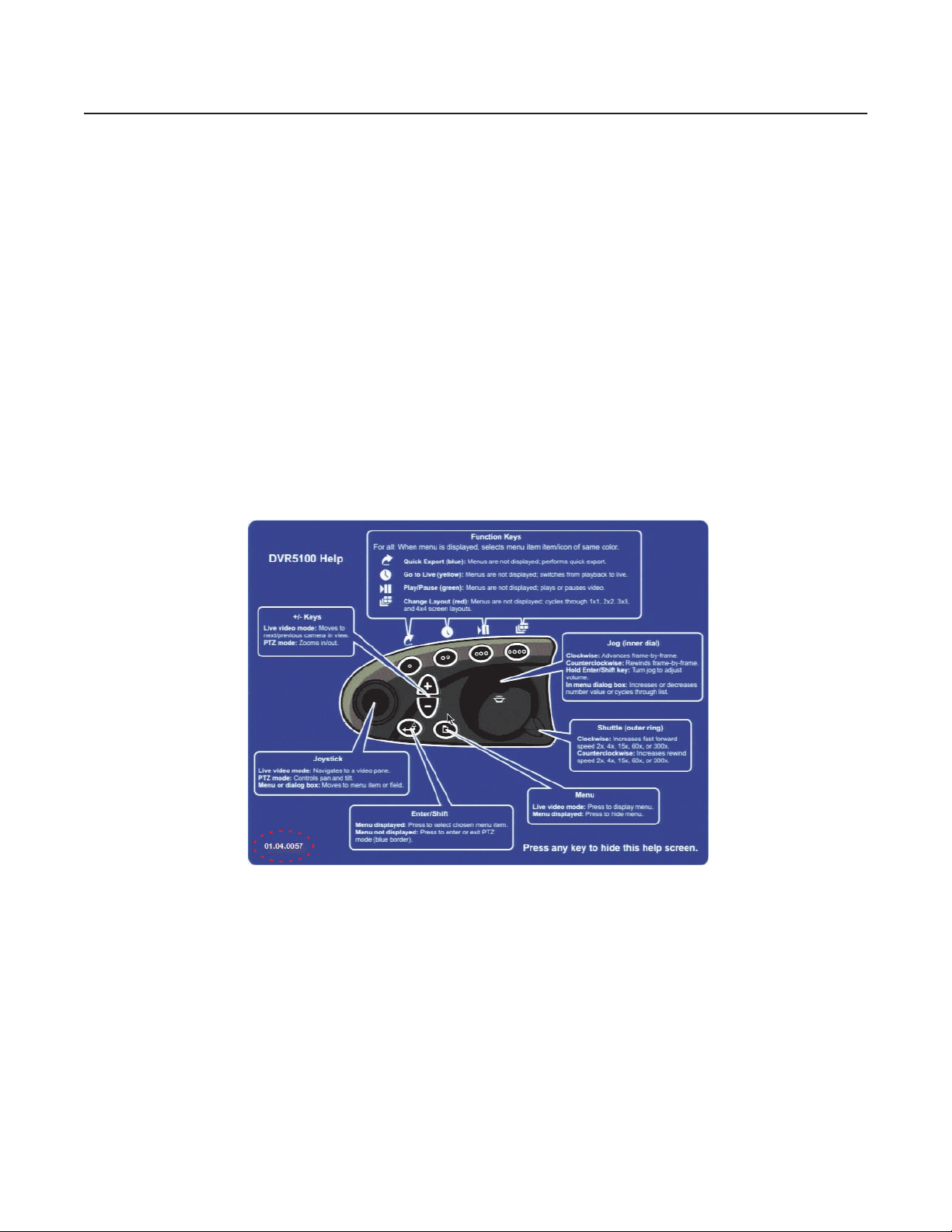
DVR5100 restarts using the existing operating system image. To check that the update is completed successfully, display the Help screen and
check the version number. Note that the release number changes to reflect each new software release.
Figure 1. DVR5100 Help Menu
C2669M (4/07) 3

DVR5100 Parts List
A USB keyboard and mouse, and a keyboard overlay (template) have been added to the existing parts list.
Qty Description
1 Pelco DVR5100 Series DVR
1 Rack-mounting kit:
2 Chassis mounting brackets with handles and thumb screws
8 Screws, 10-32 x 0.25-inch, Phillips, pan head (four for each bracket)
2 Adjustable support rail sets (each set includes one front-mounting rail and one rear-mounting rail)
6 Screws, 8-32 x 0.375-inch, Phillips, truss head
4 Screws, 10-32 x 0.5-inch, Phillips, flat head (two for each front-mounting rail)
4 Screws, 10-32 x 0.75-inch, Phillips, pan head (two for each rear-mounting rail)
10 Cage nuts (for use with square-hole racks)
1 USB PC Keyboard
1 USB Keyboard overlay (template)
1 USB PC Mouse
1–2 Terminal blocks for relays (one block for 4- and 8-channel models, two blocks for 16-channel models)
2–4 Terminal blocks for alarms (two blocks for 4- and 8-channel models, four blocks for 16-channel models)
3 Power cables (one USA standard, one European standard, and one UK standard)
2 Product identification labels (attached to unit)
3 DVR5100 Quick Start Guides
1 DVR5100 Installation manual
1 DVR5100 Operation manual (on resource CD)
1 DVR5100 Control Pad Quick Reference Guide
1 DVR5100 Remote Client Operation manual (on resource CD)
1 DVR5100 Recovery Instructions
1 Important Safety Instructions
1 Resource CD
1 Recovery disc
4 C2669M (4/07)
USB PC Keyboard, Mouse, and Template for the DVR5100
The DVR5100 provides a control pad on the front panel that allows you to access the unit’s user interface (UI). A USB PC keyboard and mouse,
and a keyboard overlay (template) are now included as an alternate method to accessing the UI. The control pad or the keyboard are used
together to make selections in the UI to set up and operate the unit. The USB mouse provides a convenient method to navigate the setup and
configuration menus.
The DVR5100 provides three USB ports: one USB port on the front panel and two USB ports on the rear panel. Any of the USB ports can be used
to connect a USB PC keyboard and mouse to the DVR5100.
To connect a keyboard and mouse to the DVR5100:
1. Connect the USB mouse to the USB port on the front panel.
2. Connect the USB PC keyboard into one of the USB ports on the rear panel.
NAVIGATING THROUGH MENUS WITH A USB PC KEYBOARD AND MOUSE
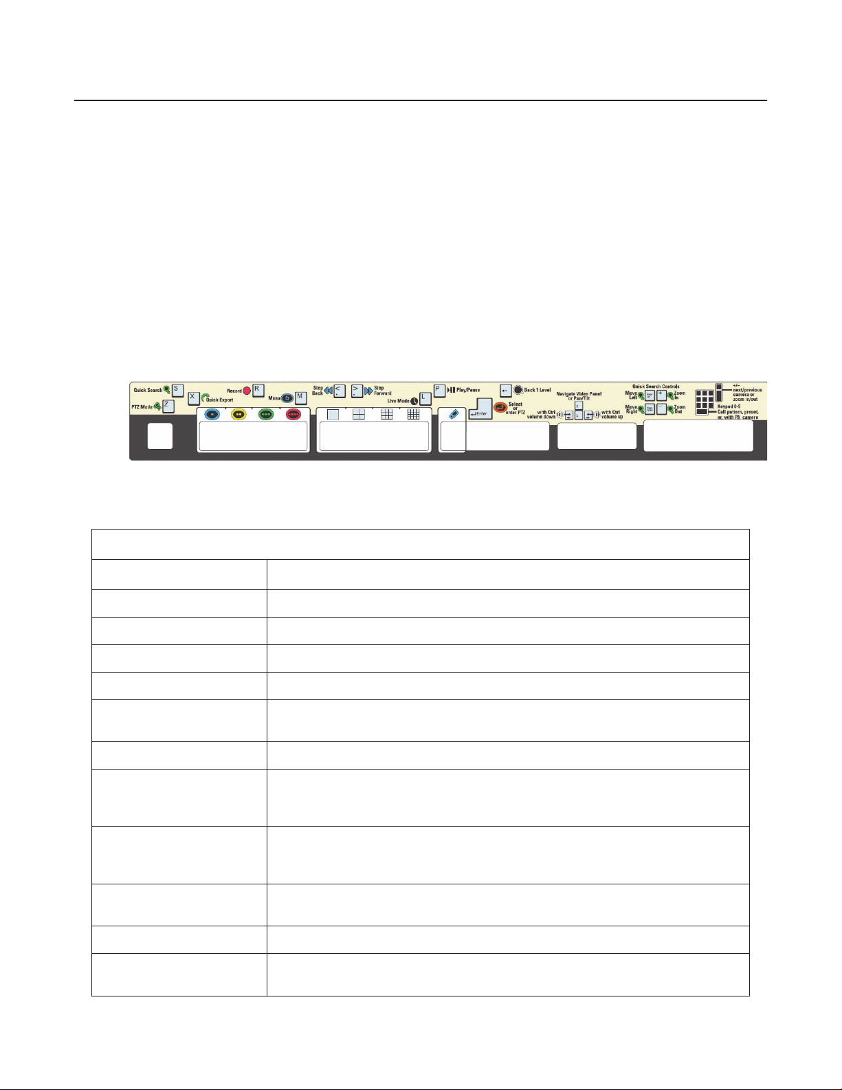
Figure 2 illustrates the USB PC keyboard overlay (template). Table A lists the USB PC keyboard and mouse operations.
Figure 2. USB PC Keyboard Template
Table A. USB PC Keyboard and Mouse Operations
USB PC Keyboard
Key
Enter Selects a menu item. Performs the same actions as the Enter/Shift key on the DVR5100 control pad.
F1-F4 Perform the same actions as the four color-coded function keys on the DVR5100 control pad.
F5-F8 Changes the screen layout from the single, 2 x 2, 3 x 3, and 4 x 4 display layouts respectively.
F9 Displays the Camera Selection dialog box.
Tab or + Tab
Esc (Escape) Closes a menu.
+ (Plus)
- (Minus)
Menu Operations
Moves to the next field or tab on a menu, or selects the next command on a dialog box or screen. Press
+Tab to move to the previous field or tab on a menu.
In live view mode, displays the next camera in the currently selected video pane. In pan/tilt/zoom (PTZ)
mode, zooms in on the scene. In the menus, expands the device tree or increases a number in a text field.
While viewing recorded video, advances the video one frame at a time.
In live view mode, displays the previous camera in the currently selected video pane. In PTZ mode, zooms
out of the scene. In the menus, closes the device tree or decreases a number in a text field. While viewing
recorded video, reverses the video one frame at a time.
Down or Up Arrow
Ctrl + Down Arrow/Ctrl + Up Arrow In the menus, increases or decreases the number in a field, or selects the next or previous entry in a list.
Right or Left Arrow
C2669M (4/07) 5
In PTZ mode, tilts the currently selected camera down or up. In the menus, selects the next or previous
entry in a list on a menu or dialog box.
In PTZ mode, pans the currently selected camera right or left. In the menus, moves to the next or previous
field on a menu or dialog box.

Table A. USB PC Keyboard and Mouse Operations (Continued)
Ctrl + Right Arrow/Ctrl + Left Arrow Increases or decreases the audio volume.
Page Up or Page Down
Scrolls forward or backward through the timeline on the Quick Search dialog box, or selects the next or
previous entry in a list on a menu or dialog box.
Backspace Returns to the previous menu; performs the same action as turning the shuttle counterclockwise.
Use any alphanumeric key on the keyboard to enter information in a text field such as a password, IP
Alphanumeric keypad
address, comment or other field. Do not enter characters that are not valid for the currently selected field.
Refer to the specific instructions for the field for guidelines on valid entries. See the descriptions in this
table for additional functions for specific characters.
< or , (comma) Plays recorded video backward.
> or . (period) Plays recorded video forward.
l Switches the currently selected video pane to live view mode.
m Displays the main menu.
p In live view mode, plays or pauses the video in the currently selected video pane.
r In live view mode, starts recording video in the currently selected video pane.
s Displays the Quick Search dialog box for the currently selected video pane.
x Opens the Quick Export dialog box.
z Switch to PTZ mode.
USB PC Mouse (For configuration use only)
Left-Click
Selects a menu icon, text field, or check box; executes a command key; and displays the next tab on a
configuration screen. Point and click on an up or down arrow next to a text field to increase or decrease
the number or to select the next or previous entry in a list.
6 C2669M (4/07)
Auto Login
The DVR5100 comes with four pre-defined user profiles: Administrator, Manager, Operator, and Guest. The first time you start the DVR5100, the
system automatically logs in using the admin user after 60 seconds if an operator does not select a specific user at the login screen. This feature
allows the system to automatically log in as the designated user each time the DVR is rebooted (for example, after a power failure or when the
unit is restarted for any purpose). You can enable or disable the feature from the System Configuration screen. In addition, you can choose a
specific user for subsequent log ins.
NOTE: As a security precaution, you should change the user ID for auto-login as part of the configuration and setup process. Consider selecting
Guest as the default user ID or create a new user ID and password with limited access. Using a Guest user assures that system settings are not
accessible inadvertently.
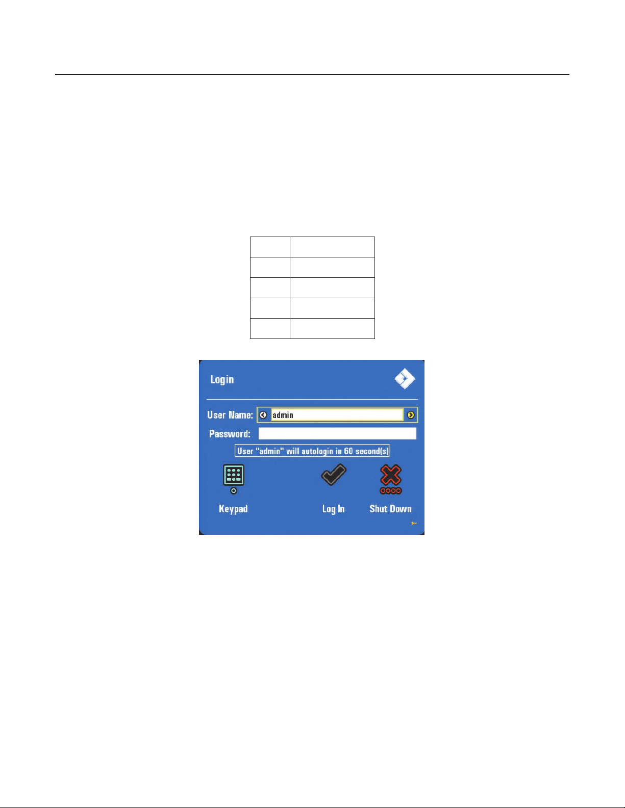
Table B lists the default user IDs and passwords. Figure 3 shows the login screen.
Table B. Default User IDs and Passwords
User ID Password
admin admin or 23646
manager manager or 6262437
operator operator or 67372867
guest guest or 48378
Figure 3. Auto Login Menu
C2669M (4/07) 7
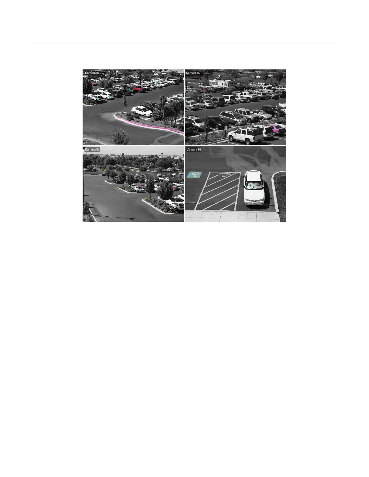
Automatically Assigning Cameras to the Workspace
The DVR5100 automatically assigns or prepopulates cameras to the workspace. Cameras are configured starting at the top left video pane and
ending at the lower right video pane. Figure 4 shows a 2 x 2 configuration.
Figure 4. Auto Camera Assignment
8 C2669M (4/07)

Extending Video Retention by Changing Frame Rate
Traditionally, users looking to retain video for as long as possible were forced to compromise between recording at a lower quality and a lower
frame rate. The DVR5100 now introduces a powerful alternative to achieving longer retention times.
Pelco's patented EnduraStor
one image, one image every two seconds, and one image every three seconds after a defined period of time. Instead of recording from the very
beginning at a very slow rate, EnduraStor allows you to retain high frame rate video for the time period it is needed most. When programming
the EnduraStor delay period, you can customize the storage options to suit your operation model. You can get the retention targets you are
looking for while realizing the benefit of having 30/25 images per second (ips) video available for investigation and export. The DVR5100 now
provides additional flexibility that allows you to optimize your recorded video to meet budget constraints.
Table C lists the recording rates.
™
technology provides you with the ability to prune recorded video down to five images, three images, two images,
Table C. Options for Picture Quality
Frame Rate
Quality Options Resolution
High 30/25 4CIF 30 (25) 2 images every second
High 15/12.5 4CIF 15 (12.5) 2 images every second
High 10/8.3 4CIF 10 (8.3) 2 images every second
High 6/5 4CIF 6 (5) 2 images every second
Medium 30/25 2CIF 30 (25) 2 images every second
Medium 15/12.5 2CIF 15 (12.5) 2 images every second
Medium 10/8.3 2CIF 10 (8.3) 2 images every second
Medium 6/5 2CIF 6 (5) 2 images every second
Low 30/25 CIF 30 (25) 2 images every second
Low 15/12.5 CIF 15 (12.5) 2 images every second
Low 10/8.3 CIF 10 (8.3) 2 images every second
Low 6/5 CIF 6 (5) 2 images every second
New Settings Added*
High 5 images/second 4CIF 30 (25) 5 images every second
High 3 images/second 4CIF 30 (25) 3 images every second
High 1 image/second 4CIF 30 (25) 1 image every second
High 1 image/2 seconds 4CIF 30 (25) 1 image every 2 seconds
High 1 image/3 seconds 4CIF 30 (25) 1 image every 3 seconds
High 1 image/5 seconds 4CIF 30 (25) 1 image every 5 second
Medium 5 images/second 2CIF 30 (25) 5 images every second
Medium 3 images/second 2CIF 30 (25) 3 images every second
Medium 1 image/second 2CIF 30 (25) 1 images every second
Medium 1 image/2 seconds 2CIF 30 (25) 1 image every 2 seconds
Medium 1 image/3 seconds 2CIF 30 (25) 1 image every 3 seconds
Low 5 images/second CIF 30 (25) 5 images every second
Low 3 images/second CIF 30 (25) 3 images every second
Low 1 image/second CIF 30 (25) 1image every second
Low 1 image/2 seconds CIF 30 (25) 1 image every 2 seconds
Low 1 image/3 seconds CIF 30 (25) 1 image every 3 seconds
NTSC (PAL) EnduraStor Rate
*New settings are recorded at 30/25 ips unless EnduraStor is enabled, at which point
recorded video is pruned to the designated image rate. For information on using
EnduraStor, refer to the DVR5100 Series Digital Video Recorder Installation manual
(C1695M).
C2669M (4/07) 9
•
NOTES:
The default setting for the DVR5100 frame rate was formerly Low 30/25, EnduraStor not enabled.
The default setting for the DVR5100 frame rates is now Low 1 image/second, EnduraStor enabled after 12 hours.
Remote Client
The DVR5100 Remote Client has the following new features:
• Digital Zoom Controls
• Synchronization in Quick Search
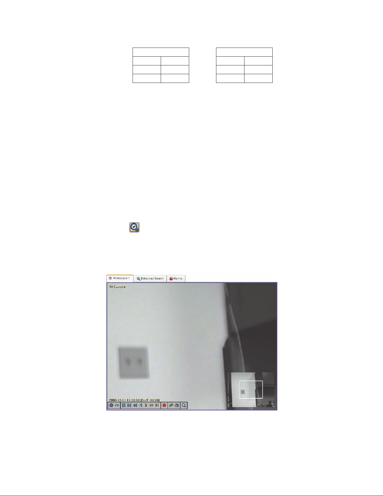
DIGITAL ZOOM CONTROLS
Similar to controlling PTZ on a camera, digital zoom controls let you zoom in on specific areas of the video that you are viewing. Digital zoom
controls work on any video, not just on video recorded on a camera that supports PTZ functions. This feature is also available while viewing
exported video with the Endura Player. To use digital zoom controls, you must be viewing video from a camera in single view (1 x 1).
•
Table D. Image Resolutions (in Pixels)
NTSC Resolutions PAL Resolutions
4CIF 704 x 480 4CIF 704 x 576
2CIF 704 x 240 2CIF 704 x 288
CIF 352 x 240 CIF 352 x 288
1. Select a camera and switch to a 1 x 1 view.
2. Click the Digital Zoom button . The view displays the video with a picture within the picture.
3. Click the mouse anywhere in the view, and then roll the center wheel of the mouse away from you to zoom in. To zoom out of the picture,
roll the center wheel of the mouse toward you.
To zoom in or out on a different area of the scene, press and hold the left mouse button anywhere in the picture, and then move the mouse in any
direction. A white frame inside the smaller picture indicates which part of the video you are working with.
Figure 5. Digital Zoom Sample
10 C2669M (4/07)
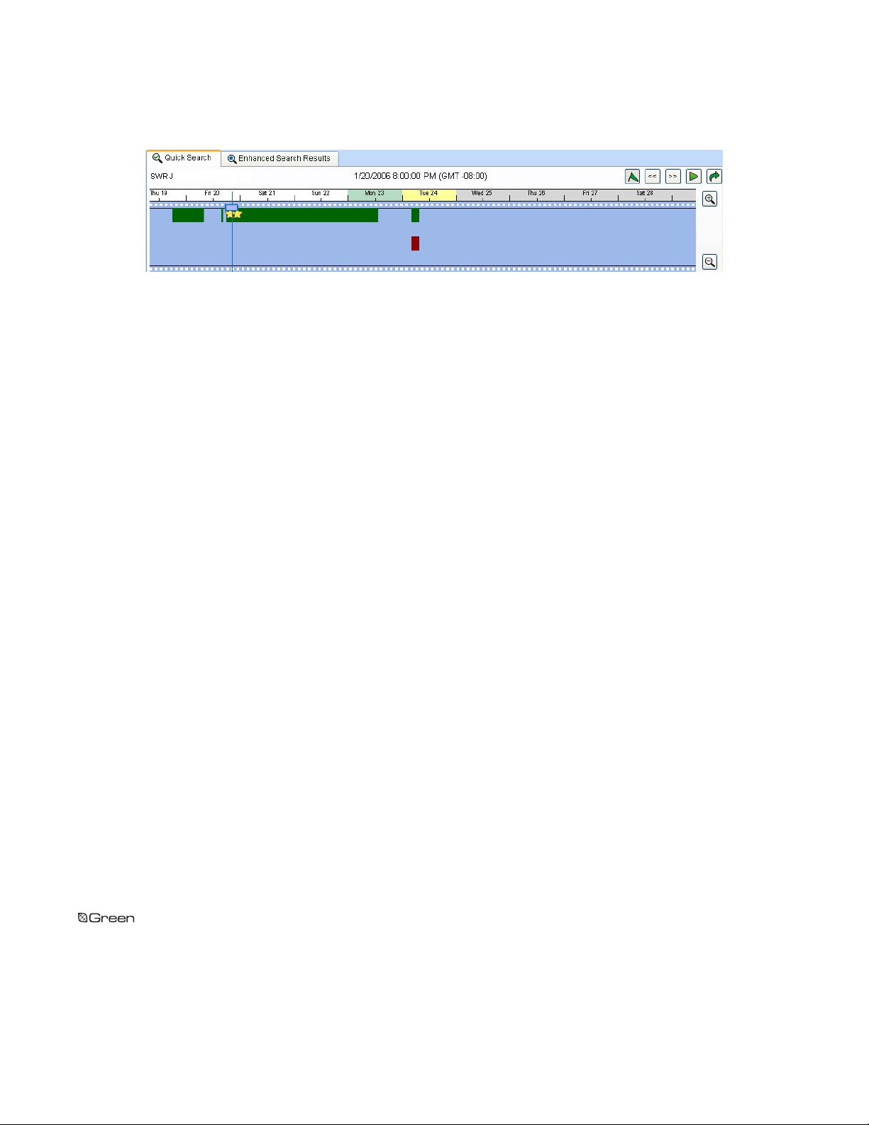
TIMELINE SYNCHRONIZATION IN QUICK SEARCH
The cursor in the Quick Search display now tracks with the video. You can move the cursor to any point on the timeline to instantly play back
video from that time.
Figure 6. Quick Search
The materials used in the manufacture of this document and its components are compliant to the requirements of Directive 2002/95/EC.
REVISION HISTORY
Manual # Date Comments
C2669M 4/07 Original version.
Pelco, the Pelco logo, Camclosure, Esprit, ExSite, Genex, Legacy, and Spectra are registered trademarks of Pelco. ©Copyright 2007, Pelco. All rights reserved.
Endura, EnduraStor, and Spectra III are trademarks of Pelco.
DLP is a registered trademark of Texas Instruments, Inc.
C2669M (4/07) 11

Australia
Canada
|
South Africa
|
Finland
Spain
|
Worldwide Headquarters
3500 Pelco Way
Clovis, California 93612 USA
USA & Canada
Tel: 800/289-9100
Fax: 800/289-9150
International
Tel: 1-559/292-1981
Fax: 1-559/348-1120
www.pelco.com
ISO9001
France
Germany
|
Sweden
|
|
|
Italy
|
United Arab Emirates
|
Macau
|
The Netherlands
|
United Kingdom
Russia
|
United States
|
Singapore
|
OPERATION
DVR5100 Series
Digital Video Recorder
C1696M (8/06)


Contents
About the DVR5100 Series Digital Video Recorder
Getting Started . . . . . . . . . . . . . . . . . . . . . . . . . . . . . . . . . . . . . . . . . . . . . . . . . . . . . . . . . . . . . . . . . . . . . . . . . . . . . . . . . . . . . . . . . . . . . . . . . . . . . . . 9
Starting and Stopping the DVR5100
Re-Entering Login Information . . . . . . . . . . . . . . . . . . . . . . . . . . . . . . . . . . . . . . . . . . . . . . . . . . . . . . . . . . . . . . . . . . . . . . . . . . . . . . . . . . . . . . 10
Shutting Down the DVR5100 . . . . . . . . . . . . . . . . . . . . . . . . . . . . . . . . . . . . . . . . . . . . . . . . . . . . . . . . . . . . . . . . . . . . . . . . . . . . . . . . . . . . . . . 11
Logging Out . . . . . . . . . . . . . . . . . . . . . . . . . . . . . . . . . . . . . . . . . . . . . . . . . . . . . . . . . . . . . . . . . . . . . . . . . . . . . . . . . . . . . . . . . . . . . . . . . . . . 12
Understanding DVR Controls and Menus
Front Panel Indicators . . . . . . . . . . . . . . . . . . . . . . . . . . . . . . . . . . . . . . . . . . . . . . . . . . . . . . . . . . . . . . . . . . . . . . . . . . . . . . . . . . . . . . . . . . . . 13
DVR5100 Control Pad . . . . . . . . . . . . . . . . . . . . . . . . . . . . . . . . . . . . . . . . . . . . . . . . . . . . . . . . . . . . . . . . . . . . . . . . . . . . . . . . . . . . . . . . . . . . . 14
Navigating Through Menus with the KBD5000 Keyboard . . . . . . . . . . . . . . . . . . . . . . . . . . . . . . . . . . . . . . . . . . . . . . . . . . . . . . . . . . . . . . . . 16
Navigating Through Menus with a PC Keyboard and Mouse . . . . . . . . . . . . . . . . . . . . . . . . . . . . . . . . . . . . . . . . . . . . . . . . . . . . . . . . . . . . . . 18
Overview of Navigation and Controls . . . . . . . . . . . . . . . . . . . . . . . . . . . . . . . . . . . . . . . . . . . . . . . . . . . . . . . . . . . . . . . . . . . . . . . . . . . . . . . . . . . . . 20
Displaying and Hiding the System Menus . . . . . . . . . . . . . . . . . . . . . . . . . . . . . . . . . . . . . . . . . . . . . . . . . . . . . . . . . . . . . . . . . . . . . . . . . . . . 21
Navigating to and Selecting a Menu Item . . . . . . . . . . . . . . . . . . . . . . . . . . . . . . . . . . . . . . . . . . . . . . . . . . . . . . . . . . . . . . . . . . . . . . . . . . . . 21
Using the Control Pad to Enter Characters . . . . . . . . . . . . . . . . . . . . . . . . . . . . . . . . . . . . . . . . . . . . . . . . . . . . . . . . . . . . . . . . . . . . . . . . . . . . 22
Showing and Hiding Online Help Information . . . . . . . . . . . . . . . . . . . . . . . . . . . . . . . . . . . . . . . . . . . . . . . . . . . . . . . . . . . . . . . . . . . . . . . . . . 23
Activating On-Screen Menus . . . . . . . . . . . . . . . . . . . . . . . . . . . . . . . . . . . . . . . . . . . . . . . . . . . . . . . . . . . . . . . . . . . . . . . . . . . . . . . . . . 16
Activating Live and Playback Controls . . . . . . . . . . . . . . . . . . . . . . . . . . . . . . . . . . . . . . . . . . . . . . . . . . . . . . . . . . . . . . . . . . . . . . . . . . . 17
Joystick . . . . . . . . . . . . . . . . . . . . . . . . . . . . . . . . . . . . . . . . . . . . . . . . . . . . . . . . . . . . . . . . . . . . . . . . . . . . . . . . . . . . . . . . . . . . . . . . . . . 21
Function Keys on the Control Pad . . . . . . . . . . . . . . . . . . . . . . . . . . . . . . . . . . . . . . . . . . . . . . . . . . . . . . . . . . . . . . . . . . . . . . . . . . . . . . . 21
Using the Jog/Shuttle to Navigate Through Menus . . . . . . . . . . . . . . . . . . . . . . . . . . . . . . . . . . . . . . . . . . . . . . . . . . . . . . . . . . . . . . . . 22
On-Screen Menus . . . . . . . . . . . . . . . . . . . . . . . . . . . . . . . . . . . . . . . . . . . . . . . . . . . . . . . . . . . . . . . . . . . . . . . . . . . . . . . . . . . . . . . . . . . . . . . . . . . . 24
DVR5100 Main Menu . . . . . . . . . . . . . . . . . . . . . . . . . . . . . . . . . . . . . . . . . . . . . . . . . . . . . . . . . . . . . . . . . . . . . . . . . . . . . . . . . . . . . . . . . . . . 24
Cameras Menu . . . . . . . . . . . . . . . . . . . . . . . . . . . . . . . . . . . . . . . . . . . . . . . . . . . . . . . . . . . . . . . . . . . . . . . . . . . . . . . . . . . . . . . . . . . . . 24
Actions Menu . . . . . . . . . . . . . . . . . . . . . . . . . . . . . . . . . . . . . . . . . . . . . . . . . . . . . . . . . . . . . . . . . . . . . . . . . . . . . . . . . . . . . . . . . . . . . . 24
Search/Export Menu . . . . . . . . . . . . . . . . . . . . . . . . . . . . . . . . . . . . . . . . . . . . . . . . . . . . . . . . . . . . . . . . . . . . . . . . . . . . . . . . . . . . . . . . . 25
Setup Window . . . . . . . . . . . . . . . . . . . . . . . . . . . . . . . . . . . . . . . . . . . . . . . . . . . . . . . . . . . . . . . . . . . . . . . . . . . . . . . . . . . . . . . . . . . . . 25
Operating the DVR5100
Monitoring Live Video
Selecting a Video Pane . . . . . . . . . . . . . . . . . . . . . . . . . . . . . . . . . . . . . . . . . . . . . . . . . . . . . . . . . . . . . . . . . . . . . . . . . . . . . . . . . . . . . . . . . . . 26
Changing Screen Layout . . . . . . . . . . . . . . . . . . . . . . . . . . . . . . . . . . . . . . . . . . . . . . . . . . . . . . . . . . . . . . . . . . . . . . . . . . . . . . . . . . . . . . . . . . 26
Viewing a Specific Camera . . . . . . . . . . . . . . . . . . . . . . . . . . . . . . . . . . . . . . . . . . . . . . . . . . . . . . . . . . . . . . . . . . . . . . . . . . . . . . . . . . . . . . . . 27
Moving Through the Camera Sequence . . . . . . . . . . . . . . . . . . . . . . . . . . . . . . . . . . . . . . . . . . . . . . . . . . . . . . . . . . . . . . . . . . . . . . . . . . . . . . 28
Working With Cameras . . . . . . . . . . . . . . . . . . . . . . . . . . . . . . . . . . . . . . . . . . . . . . . . . . . . . . . . . . . . . . . . . . . . . . . . . . . . . . . . . . . . . . . . . . . 29
Adjusting the Iris . . . . . . . . . . . . . . . . . . . . . . . . . . . . . . . . . . . . . . . . . . . . . . . . . . . . . . . . . . . . . . . . . . . . . . . . . . . . . . . . . . . . . . . . . . . . 29
Adjust the Focus . . . . . . . . . . . . . . . . . . . . . . . . . . . . . . . . . . . . . . . . . . . . . . . . . . . . . . . . . . . . . . . . . . . . . . . . . . . . . . . . . . . . . . . . . . . . 31
Repositioning a Camera With PTZ Capabilities . . . . . . . . . . . . . . . . . . . . . . . . . . . . . . . . . . . . . . . . . . . . . . . . . . . . . . . . . . . . . . . . . . . . 32
Accessing Camera Menus . . . . . . . . . . . . . . . . . . . . . . . . . . . . . . . . . . . . . . . . . . . . . . . . . . . . . . . . . . . . . . . . . . . . . . . . . . . . . . . . . . . . 33
Adjusting Audio . . . . . . . . . . . . . . . . . . . . . . . . . . . . . . . . . . . . . . . . . . . . . . . . . . . . . . . . . . . . . . . . . . . . . . . . . . . . . . . . . . . . . . . . . . . . . . . . . 34
Responding to Alarms . . . . . . . . . . . . . . . . . . . . . . . . . . . . . . . . . . . . . . . . . . . . . . . . . . . . . . . . . . . . . . . . . . . . . . . . . . . . . . . . . . . . . . . . . . . . . . . . . 35
Acknowledging an Alarm Event . . . . . . . . . . . . . . . . . . . . . . . . . . . . . . . . . . . . . . . . . . . . . . . . . . . . . . . . . . . . . . . . . . . . . . . . . . . . . . . . . . . . . 35
Requesting a Reminder for an Alarm Event . . . . . . . . . . . . . . . . . . . . . . . . . . . . . . . . . . . . . . . . . . . . . . . . . . . . . . . . . . . . . . . . . . . . . . . . . . . 36
Viewing Comments . . . . . . . . . . . . . . . . . . . . . . . . . . . . . . . . . . . . . . . . . . . . . . . . . . . . . . . . . . . . . . . . . . . . . . . . . . . . . . . . . . . . . . . . . . . . . . 37
Executing Scripts . . . . . . . . . . . . . . . . . . . . . . . . . . . . . . . . . . . . . . . . . . . . . . . . . . . . . . . . . . . . . . . . . . . . . . . . . . . . . . . . . . . . . . . . . . . . . . . . . . . . 38
Working with Scripts . . . . . . . . . . . . . . . . . . . . . . . . . . . . . . . . . . . . . . . . . . . . . . . . . . . . . . . . . . . . . . . . . . . . . . . . . . . . . . . . . . . . . . . . . . . . . 38
Activating Relays . . . . . . . . . . . . . . . . . . . . . . . . . . . . . . . . . . . . . . . . . . . . . . . . . . . . . . . . . . . . . . . . . . . . . . . . . . . . . . . . . . . . . . . . . . . . . . . . . . . . 40
C1696M (8/06) 3

Using Patterns, Presets, and Scans . . . . . . . . . . . . . . . . . . . . . . . . . . . . . . . . . . . . . . . . . . . . . . . . . . . . . . . . . . . . . . . . . . . . . . . . . . . . . . . . . . . . . . 42
Activating PTZ Patterns . . . . . . . . . . . . . . . . . . . . . . . . . . . . . . . . . . . . . . . . . . . . . . . . . . . . . . . . . . . . . . . . . . . . . . . . . . . . . . . . . . . . . . . . . . . 42
Stopping a Pattern . . . . . . . . . . . . . . . . . . . . . . . . . . . . . . . . . . . . . . . . . . . . . . . . . . . . . . . . . . . . . . . . . . . . . . . . . . . . . . . . . . . . . . . . . . . . . . . 43
Activating Presets . . . . . . . . . . . . . . . . . . . . . . . . . . . . . . . . . . . . . . . . . . . . . . . . . . . . . . . . . . . . . . . . . . . . . . . . . . . . . . . . . . . . . . . . . . . . . . . 43
Activating Scans . . . . . . . . . . . . . . . . . . . . . . . . . . . . . . . . . . . . . . . . . . . . . . . . . . . . . . . . . . . . . . . . . . . . . . . . . . . . . . . . . . . . . . . . . . . . . . . . 44
Activating Auxiliary Commands (Wiper) . . . . . . . . . . . . . . . . . . . . . . . . . . . . . . . . . . . . . . . . . . . . . . . . . . . . . . . . . . . . . . . . . . . . . . . . . . . . . . . . . . . 45
Searching for Video . . . . . . . . . . . . . . . . . . . . . . . . . . . . . . . . . . . . . . . . . . . . . . . . . . . . . . . . . . . . . . . . . . . . . . . . . . . . . . . . . . . . . . . . . . . . . . . . . . 46
Quick Search . . . . . . . . . . . . . . . . . . . . . . . . . . . . . . . . . . . . . . . . . . . . . . . . . . . . . . . . . . . . . . . . . . . . . . . . . . . . . . . . . . . . . . . . . . . . . . . . . . . 46
Performing a Quick Search . . . . . . . . . . . . . . . . . . . . . . . . . . . . . . . . . . . . . . . . . . . . . . . . . . . . . . . . . . . . . . . . . . . . . . . . . . . . . . . . . . . . 47
Enhanced Search . . . . . . . . . . . . . . . . . . . . . . . . . . . . . . . . . . . . . . . . . . . . . . . . . . . . . . . . . . . . . . . . . . . . . . . . . . . . . . . . . . . . . . . . . . . . . . . . 48
Performing an Enhanced Search . . . . . . . . . . . . . . . . . . . . . . . . . . . . . . . . . . . . . . . . . . . . . . . . . . . . . . . . . . . . . . . . . . . . . . . . . . . . . . . . 49
Playing a Video Clip . . . . . . . . . . . . . . . . . . . . . . . . . . . . . . . . . . . . . . . . . . . . . . . . . . . . . . . . . . . . . . . . . . . . . . . . . . . . . . . . . . . . . . . . . . . . . . 52
Playback Speeds for Recorded Video . . . . . . . . . . . . . . . . . . . . . . . . . . . . . . . . . . . . . . . . . . . . . . . . . . . . . . . . . . . . . . . . . . . . . . . . . . . . . . . . 53
Locking and Unlocking a Video Clip . . . . . . . . . . . . . . . . . . . . . . . . . . . . . . . . . . . . . . . . . . . . . . . . . . . . . . . . . . . . . . . . . . . . . . . . . . . . . . . . . . 53
Marking an Event . . . . . . . . . . . . . . . . . . . . . . . . . . . . . . . . . . . . . . . . . . . . . . . . . . . . . . . . . . . . . . . . . . . . . . . . . . . . . . . . . . . . . . . . . . . . . . . . 54
Exporting Video . . . . . . . . . . . . . . . . . . . . . . . . . . . . . . . . . . . . . . . . . . . . . . . . . . . . . . . . . . . . . . . . . . . . . . . . . . . . . . . . . . . . . . . . . . . . . . . . . . . . . . 56
Capturing a Snapshot (Still Image) . . . . . . . . . . . . . . . . . . . . . . . . . . . . . . . . . . . . . . . . . . . . . . . . . . . . . . . . . . . . . . . . . . . . . . . . . . . . . . . . . . . . . . . 60
4 C1696M (8/06)

List of Illustrations
1 DVR5100 Network Diagram . . . . . . . . . . . . . . . . . . . . . . . . . . . . . . . . . . . . . . . . . . . . . . . . . . . . . . . . . . . . . . . . . . . . . . . . . . . . . . . . . . . . . . . 8
2 Login Dialog Box With On-Screen Keyboard . . . . . . . . . . . . . . . . . . . . . . . . . . . . . . . . . . . . . . . . . . . . . . . . . . . . . . . . . . . . . . . . . . . . . . . . 10
3 Retry Login Dialog Box . . . . . . . . . . . . . . . . . . . . . . . . . . . . . . . . . . . . . . . . . . . . . . . . . . . . . . . . . . . . . . . . . . . . . . . . . . . . . . . . . . . . . . . . . . 10
4 Selecting Logout From the Main Menu . . . . . . . . . . . . . . . . . . . . . . . . . . . . . . . . . . . . . . . . . . . . . . . . . . . . . . . . . . . . . . . . . . . . . . . . . . . . 11
5 Login Dialog Box . . . . . . . . . . . . . . . . . . . . . . . . . . . . . . . . . . . . . . . . . . . . . . . . . . . . . . . . . . . . . . . . . . . . . . . . . . . . . . . . . . . . . . . . . . . . . . . 12
6 Logging Out . . . . . . . . . . . . . . . . . . . . . . . . . . . . . . . . . . . . . . . . . . . . . . . . . . . . . . . . . . . . . . . . . . . . . . . . . . . . . . . . . . . . . . . . . . . . . . . . . . 12
7 DVR5100 Front Panel Indicators . . . . . . . . . . . . . . . . . . . . . . . . . . . . . . . . . . . . . . . . . . . . . . . . . . . . . . . . . . . . . . . . . . . . . . . . . . . . . . . . . . . 13
8 DVR5100 Control Pad . . . . . . . . . . . . . . . . . . . . . . . . . . . . . . . . . . . . . . . . . . . . . . . . . . . . . . . . . . . . . . . . . . . . . . . . . . . . . . . . . . . . . . . . . . 14
9 Shortcut Menu Accessible From a Mouse . . . . . . . . . . . . . . . . . . . . . . . . . . . . . . . . . . . . . . . . . . . . . . . . . . . . . . . . . . . . . . . . . . . . . . . . . . 19
10 DVR5100 Main Window . . . . . . . . . . . . . . . . . . . . . . . . . . . . . . . . . . . . . . . . . . . . . . . . . . . . . . . . . . . . . . . . . . . . . . . . . . . . . . . . . . . . . . . . 20
11 DVR5100 Main Menu . . . . . . . . . . . . . . . . . . . . . . . . . . . . . . . . . . . . . . . . . . . . . . . . . . . . . . . . . . . . . . . . . . . . . . . . . . . . . . . . . . . . . . . . . . 21
12 Control Pad Color-Coded Function Keys . . . . . . . . . . . . . . . . . . . . . . . . . . . . . . . . . . . . . . . . . . . . . . . . . . . . . . . . . . . . . . . . . . . . . . . . . . . . . 21
13 Sample Icon Path . . . . . . . . . . . . . . . . . . . . . . . . . . . . . . . . . . . . . . . . . . . . . . . . . . . . . . . . . . . . . . . . . . . . . . . . . . . . . . . . . . . . . . . . . . . . . . 22
14 On-Screen Keyboard . . . . . . . . . . . . . . . . . . . . . . . . . . . . . . . . . . . . . . . . . . . . . . . . . . . . . . . . . . . . . . . . . . . . . . . . . . . . . . . . . . . . . . . . . . . 22
15 Help Menu . . . . . . . . . . . . . . . . . . . . . . . . . . . . . . . . . . . . . . . . . . . . . . . . . . . . . . . . . . . . . . . . . . . . . . . . . . . . . . . . . . . . . . . . . . . . . . . . . . . 23
16 Online Help for the Control Pad . . . . . . . . . . . . . . . . . . . . . . . . . . . . . . . . . . . . . . . . . . . . . . . . . . . . . . . . . . . . . . . . . . . . . . . . . . . . . . . . . . 23
17 DVR5100 Main Menu . . . . . . . . . . . . . . . . . . . . . . . . . . . . . . . . . . . . . . . . . . . . . . . . . . . . . . . . . . . . . . . . . . . . . . . . . . . . . . . . . . . . . . . . . . 24
18 Cameras Menu . . . . . . . . . . . . . . . . . . . . . . . . . . . . . . . . . . . . . . . . . . . . . . . . . . . . . . . . . . . . . . . . . . . . . . . . . . . . . . . . . . . . . . . . . . . . . . . 24
19 Actions Menu . . . . . . . . . . . . . . . . . . . . . . . . . . . . . . . . . . . . . . . . . . . . . . . . . . . . . . . . . . . . . . . . . . . . . . . . . . . . . . . . . . . . . . . . . . . . . . . . 24
20 Search Export Menu . . . . . . . . . . . . . . . . . . . . . . . . . . . . . . . . . . . . . . . . . . . . . . . . . . . . . . . . . . . . . . . . . . . . . . . . . . . . . . . . . . . . . . . . . . . 25
21 Setup Window . . . . . . . . . . . . . . . . . . . . . . . . . . . . . . . . . . . . . . . . . . . . . . . . . . . . . . . . . . . . . . . . . . . . . . . . . . . . . . . . . . . . . . . . . . . . . . . . 25
22 Displaying Video in a 2x2 Mode . . . . . . . . . . . . . . . . . . . . . . . . . . . . . . . . . . . . . . . . . . . . . . . . . . . . . . . . . . . . . . . . . . . . . . . . . . . . . . . . . . 27
23 Main Menu . . . . . . . . . . . . . . . . . . . . . . . . . . . . . . . . . . . . . . . . . . . . . . . . . . . . . . . . . . . . . . . . . . . . . . . . . . . . . . . . . . . . . . . . . . . . . . . . . . 27
24 Camera Menu . . . . . . . . . . . . . . . . . . . . . . . . . . . . . . . . . . . . . . . . . . . . . . . . . . . . . . . . . . . . . . . . . . . . . . . . . . . . . . . . . . . . . . . . . . . . . . . . . 27
25 Camera List . . . . . . . . . . . . . . . . . . . . . . . . . . . . . . . . . . . . . . . . . . . . . . . . . . . . . . . . . . . . . . . . . . . . . . . . . . . . . . . . . . . . . . . . . . . . . . . . . . . 28
26 Displaying a Camera in a Video Pane . . . . . . . . . . . . . . . . . . . . . . . . . . . . . . . . . . . . . . . . . . . . . . . . . . . . . . . . . . . . . . . . . . . . . . . . . . . . . . 28
27 Camera List . . . . . . . . . . . . . . . . . . . . . . . . . . . . . . . . . . . . . . . . . . . . . . . . . . . . . . . . . . . . . . . . . . . . . . . . . . . . . . . . . . . . . . . . . . . . . . . . . . 29
28 Select Camera Menu . . . . . . . . . . . . . . . . . . . . . . . . . . . . . . . . . . . . . . . . . . . . . . . . . . . . . . . . . . . . . . . . . . . . . . . . . . . . . . . . . . . . . . . . . . . 29
29 Iris Dialog Box . . . . . . . . . . . . . . . . . . . . . . . . . . . . . . . . . . . . . . . . . . . . . . . . . . . . . . . . . . . . . . . . . . . . . . . . . . . . . . . . . . . . . . . . . . . . . . . . 30
30 Open Iris Control . . . . . . . . . . . . . . . . . . . . . . . . . . . . . . . . . . . . . . . . . . . . . . . . . . . . . . . . . . . . . . . . . . . . . . . . . . . . . . . . . . . . . . . . . . . . . . 30
31 Close Iris Control . . . . . . . . . . . . . . . . . . . . . . . . . . . . . . . . . . . . . . . . . . . . . . . . . . . . . . . . . . . . . . . . . . . . . . . . . . . . . . . . . . . . . . . . . . . . . . 30
32 Select Camera Menu . . . . . . . . . . . . . . . . . . . . . . . . . . . . . . . . . . . . . . . . . . . . . . . . . . . . . . . . . . . . . . . . . . . . . . . . . . . . . . . . . . . . . . . . . . . 31
33 Focus Dialog Box . . . . . . . . . . . . . . . . . . . . . . . . . . . . . . . . . . . . . . . . . . . . . . . . . . . . . . . . . . . . . . . . . . . . . . . . . . . . . . . . . . . . . . . . . . . . . . 31
34 Focus Closer to An Object . . . . . . . . . . . . . . . . . . . . . . . . . . . . . . . . . . . . . . . . . . . . . . . . . . . . . . . . . . . . . . . . . . . . . . . . . . . . . . . . . . . . . . . 32
35 Focus Farther Away From an Object . . . . . . . . . . . . . . . . . . . . . . . . . . . . . . . . . . . . . . . . . . . . . . . . . . . . . . . . . . . . . . . . . . . . . . . . . . . . . . . 32
36 PTZ Mode Indicated by Blue Border . . . . . . . . . . . . . . . . . . . . . . . . . . . . . . . . . . . . . . . . . . . . . . . . . . . . . . . . . . . . . . . . . . . . . . . . . . . . . . . 32
37 Selecting the Camera Menu . . . . . . . . . . . . . . . . . . . . . . . . . . . . . . . . . . . . . . . . . . . . . . . . . . . . . . . . . . . . . . . . . . . . . . . . . . . . . . . . . . . . . 33
38 Example of a Camera Settings Menu . . . . . . . . . . . . . . . . . . . . . . . . . . . . . . . . . . . . . . . . . . . . . . . . . . . . . . . . . . . . . . . . . . . . . . . . . . . . . . 33
39 Acknowledging an Alarm . . . . . . . . . . . . . . . . . . . . . . . . . . . . . . . . . . . . . . . . . . . . . . . . . . . . . . . . . . . . . . . . . . . . . . . . . . . . . . . . . . . . . . . 35
40 Alarm Information . . . . . . . . . . . . . . . . . . . . . . . . . . . . . . . . . . . . . . . . . . . . . . . . . . . . . . . . . . . . . . . . . . . . . . . . . . . . . . . . . . . . . . . . . . . . . 36
41 Selecting Actions on DVR5100 Main Menu . . . . . . . . . . . . . . . . . . . . . . . . . . . . . . . . . . . . . . . . . . . . . . . . . . . . . . . . . . . . . . . . . . . . . . . . . 38
42 Selecting Scripts on Actions Menu . . . . . . . . . . . . . . . . . . . . . . . . . . . . . . . . . . . . . . . . . . . . . . . . . . . . . . . . . . . . . . . . . . . . . . . . . . . . . . . . 38
43 Execute Script Dialog Box . . . . . . . . . . . . . . . . . . . . . . . . . . . . . . . . . . . . . . . . . . . . . . . . . . . . . . . . . . . . . . . . . . . . . . . . . . . . . . . . . . . . . . . 39
44 Actions Menu . . . . . . . . . . . . . . . . . . . . . . . . . . . . . . . . . . . . . . . . . . . . . . . . . . . . . . . . . . . . . . . . . . . . . . . . . . . . . . . . . . . . . . . . . . . . . . . . . 40
45 Activating a Relay . . . . . . . . . . . . . . . . . . . . . . . . . . . . . . . . . . . . . . . . . . . . . . . . . . . . . . . . . . . . . . . . . . . . . . . . . . . . . . . . . . . . . . . . . . . . . 40
46 DVR5100 Dialog Box . . . . . . . . . . . . . . . . . . . . . . . . . . . . . . . . . . . . . . . . . . . . . . . . . . . . . . . . . . . . . . . . . . . . . . . . . . . . . . . . . . . . . . . . . . . 41
47 Actions Menu . . . . . . . . . . . . . . . . . . . . . . . . . . . . . . . . . . . . . . . . . . . . . . . . . . . . . . . . . . . . . . . . . . . . . . . . . . . . . . . . . . . . . . . . . . . . . . . . 42
48 PTZ Operations Dialog Box . . . . . . . . . . . . . . . . . . . . . . . . . . . . . . . . . . . . . . . . . . . . . . . . . . . . . . . . . . . . . . . . . . . . . . . . . . . . . . . . . . . . . . 42
49 Scripts Menu . . . . . . . . . . . . . . . . . . . . . . . . . . . . . . . . . . . . . . . . . . . . . . . . . . . . . . . . . . . . . . . . . . . . . . . . . . . . . . . . . . . . . . . . . . . . . . . . . 43
50 PTZ Operations Dialog Box . . . . . . . . . . . . . . . . . . . . . . . . . . . . . . . . . . . . . . . . . . . . . . . . . . . . . . . . . . . . . . . . . . . . . . . . . . . . . . . . . . . . . . 43
51 Scripts Menu . . . . . . . . . . . . . . . . . . . . . . . . . . . . . . . . . . . . . . . . . . . . . . . . . . . . . . . . . . . . . . . . . . . . . . . . . . . . . . . . . . . . . . . . . . . . . . . . . 44
52 PTZ Operations Dialog Box . . . . . . . . . . . . . . . . . . . . . . . . . . . . . . . . . . . . . . . . . . . . . . . . . . . . . . . . . . . . . . . . . . . . . . . . . . . . . . . . . . . . . . . 44
53 Scripts Menu . . . . . . . . . . . . . . . . . . . . . . . . . . . . . . . . . . . . . . . . . . . . . . . . . . . . . . . . . . . . . . . . . . . . . . . . . . . . . . . . . . . . . . . . . . . . . . . . . 45
54 Quick Search Dialog Box . . . . . . . . . . . . . . . . . . . . . . . . . . . . . . . . . . . . . . . . . . . . . . . . . . . . . . . . . . . . . . . . . . . . . . . . . . . . . . . . . . . . . . . . 46
55 Quick Search Menu . . . . . . . . . . . . . . . . . . . . . . . . . . . . . . . . . . . . . . . . . . . . . . . . . . . . . . . . . . . . . . . . . . . . . . . . . . . . . . . . . . . . . . . . . . . . 47
56 Search Dialog Box . . . . . . . . . . . . . . . . . . . . . . . . . . . . . . . . . . . . . . . . . . . . . . . . . . . . . . . . . . . . . . . . . . . . . . . . . . . . . . . . . . . . . . . . . . . . . 48
57 Search/Export Menu . . . . . . . . . . . . . . . . . . . . . . . . . . . . . . . . . . . . . . . . . . . . . . . . . . . . . . . . . . . . . . . . . . . . . . . . . . . . . . . . . . . . . . . . . . . 49
58 Start Time Dialog Box . . . . . . . . . . . . . . . . . . . . . . . . . . . . . . . . . . . . . . . . . . . . . . . . . . . . . . . . . . . . . . . . . . . . . . . . . . . . . . . . . . . . . . . . . . 49
59 Quick Search Dialog Box . . . . . . . . . . . . . . . . . . . . . . . . . . . . . . . . . . . . . . . . . . . . . . . . . . . . . . . . . . . . . . . . . . . . . . . . . . . . . . . . . . . . . . . . 49
C1696M (8/06) 5

60 Selecting Multiple Types of Recorded Video . . . . . . . . . . . . . . . . . . . . . . . . . . . . . . . . . . . . . . . . . . . . . . . . . . . . . . . . . . . . . . . . . . . . . . . . 50
61 Selecting Multiple Cameras . . . . . . . . . . . . . . . . . . . . . . . . . . . . . . . . . . . . . . . . . . . . . . . . . . . . . . . . . . . . . . . . . . . . . . . . . . . . . . . . . . . . . 50
62 Enhanced Search Results . . . . . . . . . . . . . . . . . . . . . . . . . . . . . . . . . . . . . . . . . . . . . . . . . . . . . . . . . . . . . . . . . . . . . . . . . . . . . . . . . . . . . . . 51
63 Playing Recorded Video From the Quick Search Dialog . . . . . . . . . . . . . . . . . . . . . . . . . . . . . . . . . . . . . . . . . . . . . . . . . . . . . . . . . . . . . . . . 52
64 Enhanced Search Dialog Box . . . . . . . . . . . . . . . . . . . . . . . . . . . . . . . . . . . . . . . . . . . . . . . . . . . . . . . . . . . . . . . . . . . . . . . . . . . . . . . . . . . . . 52
65 Quick Search Lock Clip Dialog Box . . . . . . . . . . . . . . . . . . . . . . . . . . . . . . . . . . . . . . . . . . . . . . . . . . . . . . . . . . . . . . . . . . . . . . . . . . . . . . . . . 53
66 Searching for Locked Video . . . . . . . . . . . . . . . . . . . . . . . . . . . . . . . . . . . . . . . . . . . . . . . . . . . . . . . . . . . . . . . . . . . . . . . . . . . . . . . . . . . . . . 54
67 Marking an Event . . . . . . . . . . . . . . . . . . . . . . . . . . . . . . . . . . . . . . . . . . . . . . . . . . . . . . . . . . . . . . . . . . . . . . . . . . . . . . . . . . . . . . . . . . . . . 54
68 Marked Events on the Quick Search Dialog Box . . . . . . . . . . . . . . . . . . . . . . . . . . . . . . . . . . . . . . . . . . . . . . . . . . . . . . . . . . . . . . . . . . . . . . 55
69 Quick Export Screen . . . . . . . . . . . . . . . . . . . . . . . . . . . . . . . . . . . . . . . . . . . . . . . . . . . . . . . . . . . . . . . . . . . . . . . . . . . . . . . . . . . . . . . . . . . 56
70 Export Video Clip Screen . . . . . . . . . . . . . . . . . . . . . . . . . . . . . . . . . . . . . . . . . . . . . . . . . . . . . . . . . . . . . . . . . . . . . . . . . . . . . . . . . . . . . . . . 56
71 Exporting Video to a CD or DVD . . . . . . . . . . . . . . . . . . . . . . . . . . . . . . . . . . . . . . . . . . . . . . . . . . . . . . . . . . . . . . . . . . . . . . . . . . . . . . . . . . 57
72 Date Time Range Screen . . . . . . . . . . . . . . . . . . . . . . . . . . . . . . . . . . . . . . . . . . . . . . . . . . . . . . . . . . . . . . . . . . . . . . . . . . . . . . . . . . . . . . . . 57
73 Enhanced Search Dialog Box . . . . . . . . . . . . . . . . . . . . . . . . . . . . . . . . . . . . . . . . . . . . . . . . . . . . . . . . . . . . . . . . . . . . . . . . . . . . . . . . . . . . . 58
74 Export Selected Clip Dialog Box . . . . . . . . . . . . . . . . . . . . . . . . . . . . . . . . . . . . . . . . . . . . . . . . . . . . . . . . . . . . . . . . . . . . . . . . . . . . . . . . . . . 58
75 Export Message Dialog Box . . . . . . . . . . . . . . . . . . . . . . . . . . . . . . . . . . . . . . . . . . . . . . . . . . . . . . . . . . . . . . . . . . . . . . . . . . . . . . . . . . . . . 59
76 Selecting Snapshot From the Quick Export Dialog Box . . . . . . . . . . . . . . . . . . . . . . . . . . . . . . . . . . . . . . . . . . . . . . . . . . . . . . . . . . . . . . . . . 60
77 Capturing a Snapshot . . . . . . . . . . . . . . . . . . . . . . . . . . . . . . . . . . . . . . . . . . . . . . . . . . . . . . . . . . . . . . . . . . . . . . . . . . . . . . . . . . . . . . . . . . 60
6 C1696M (8/06)

List of Tables
A Default User IDs and Passwords . . . . . . . . . . . . . . . . . . . . . . . . . . . . . . . . . . . . . . . . . . . . . . . . . . . . . . . . . . . . . . . . . . . . . . . . . . . . . . . . . . . 9
B Features of the DVR5100 Front Panel . . . . . . . . . . . . . . . . . . . . . . . . . . . . . . . . . . . . . . . . . . . . . . . . . . . . . . . . . . . . . . . . . . . . . . . . . . . . . . 13
C DVR5100 Control Pad Functions. . . . . . . . . . . . . . . . . . . . . . . . . . . . . . . . . . . . . . . . . . . . . . . . . . . . . . . . . . . . . . . . . . . . . . . . . . . . . . . . . . . 14
D KBD5000 Menu Operations . . . . . . . . . . . . . . . . . . . . . . . . . . . . . . . . . . . . . . . . . . . . . . . . . . . . . . . . . . . . . . . . . . . . . . . . . . . . . . . . . . . . . . 16
E KBD5000 Live and Playback Operations . . . . . . . . . . . . . . . . . . . . . . . . . . . . . . . . . . . . . . . . . . . . . . . . . . . . . . . . . . . . . . . . . . . . . . . . . . . . 17
F USB PC Keyboard and Mouse Operations . . . . . . . . . . . . . . . . . . . . . . . . . . . . . . . . . . . . . . . . . . . . . . . . . . . . . . . . . . . . . . . . . . . . . . . . . . . 18
G Supported DVR5100 Scripts . . . . . . . . . . . . . . . . . . . . . . . . . . . . . . . . . . . . . . . . . . . . . . . . . . . . . . . . . . . . . . . . . . . . . . . . . . . . . . . . . . . . . . 38
C1696M (8/06) 7
About the DVR5100 Series Digital Video Recorder
The DVR5100 Series digital video recorder (DVR) is stand-alone or Endura-enabled, high-performance 4, 8, or 16 channel DVR. The DVR5100
combines superior forensic functions, easy-to-use interfaces, and video recording performance previously reserved for extremely high-end
systems. Digital video recorders designed for forensic applications must record video at high resolutions to capture exceptional detail and quality
required for investigative work. The DVR5100 captures video at up to 704 x 480 pixels (NTSC) or 704 x 576 pixels (PAL) at 30 ips (NTSC) or 25 ips
(PAL), providing the investigator with essential details.
The DVR5100’s remarkable performance is enhanced by the use of the EnduraStor™ storage optimization technology. EnduraStor allows video
recorded at higher frame rates to be reduced to 2 ips after a predetermined period of time, saving valuable hard disk drive space. EnduraStor,
combined with powerful motion detection capabilities and programmable recording schedules, allows the user to customize the performance of
the DVR5100 and optimize the required storage capacity.
A user-supplied USB keyboard can be connected to a DVR5100 USB port to configure the DVR5100 settings quickly and easily. Convenient front
panel controls with integrated joystick, jog, and shuttle, combined with an intuitive and simple graphical user interface (GUI), make using the
DVR easy and effortless. The front panel controls allow operation of Pelco PTZ cameras through Coaxitron
single-key export feature simplifies the exporting of video.
Flexible view options allow users to optimize the DVR for their particular application requirements. Video can be displayed on NTSC/PAL
composite, NTSC/PAL S-video, or VGA monitors. The main monitor can display one, four, nine, or sixteen images. Live and playback video can be
combined on the same screen. In addition, a programmable spot monitor provides a sequencing display on a composite monitor.
The DVR5100 uses Internet Protocol-based networking for remote accessibility and control of the DVR. All connections are made over a secure
and encrypted VPN session. For local area networks, the DVR5100’s 1 gigabit network port supports its impressive performance.
With a maximum recording speed of 30 images (NTSC) or 25 images (PAL) per camera per second at 4CIF resolution, the DVR5100 shatters
previous performance marks and establishes the best value in the industry for forensic digital video recorders. The combination of enterprise
class recording capabilities, ample internal storage, remote accessibility, and the reliability and assurance found in Pelco products makes this the
ideal DVR for unmanaged video surveillance applications typical of the retail, banking, education, and medical industries.
®
, D, or P protocol. An innovative
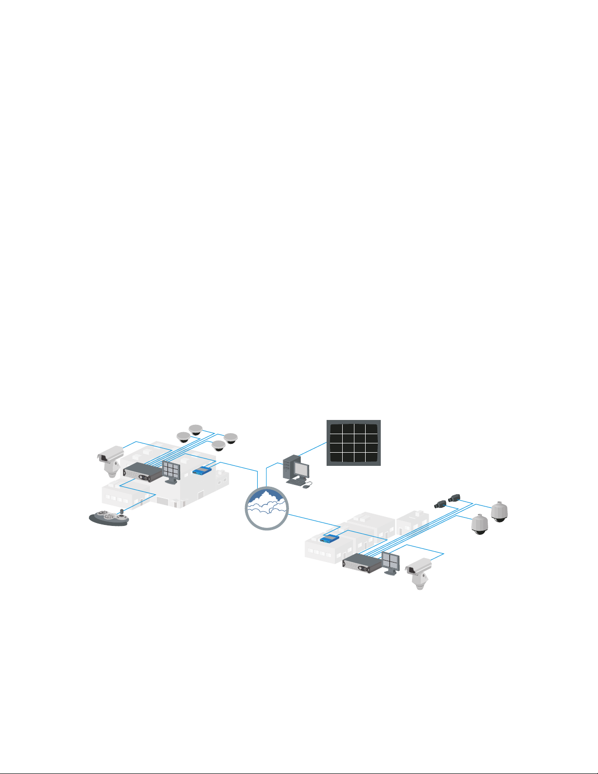
The DVR5100 can operate as a stand-alone or networked device. If the DVR5100 is going to be included in an existing network, always include
your network administrator when planning and installing the DVR5100.
16 CAMERA VIEWS
REMOTE CLIENT
NETWORK
KBD5000
Figure 1. DVR5100 Network Diagram
8 C1696M (8/06)

Getting Started
This manual describes how to operate the DVR5100 to view and record live video, search for recorded video and mark it or lock it for future use,
and to operate or adjust cameras. For information about installing and configuring the unit, refer to the installation manual.
The DVR5100 provides access to most of the functionality needed for day-to-day operations along with basic monitor setup options. For access to
advanced setup or configuration, use the DVR5100 remote client application. The DVR5100 Series DVR is available in several configurations. For
a description of the available models, refer to the DVR5100 Product Specification.
Starting and Stopping the DVR5100
When you start the DVR5100, a login dialog box automatically appears in the center of the screen (Figure 2). The following default user names
and passwords are available for the DVR5100:
The following default user names and passwords are available for the DVR5100:
Table A. Default User IDs and Passwords
User ID Password
admin admin or 23646
manager manager or 6262437
operator operator or 67372867
guest guest or 48378
Each time you start the DVR5100, you should choose the user name that is assigned a role that provides you with access to the features that you
will need. By default each user has access to the following features:
• admin: This user is assigned the Administrator role which provides full access to all of the DVR5100 features. The Administrator has
full access rights and is the only user level with permission to modify every option and value in the Setup page.
• manager: This user is assigned the Manager role which provides access to the same features available to the Operator role, with the
addition of being able to export and view all of the Setup windows.
• operator: This user is assigned the Operator role which lets you monitor live video and audio, reposition PTZ cameras, respond to
alarms, run scripts, activate relays, search for video, play it back, lock clips, and capture snapshots.
• guest: This user is assigned the Guest role which lets you monitor live video and audio, change layouts, and reposition PTZ cameras.
Contact your DVR5100 system administrator to set up additional users and roles and if you forget a password or need to change a password.
To log on to the DVR5100:
TIP: You can use an optional KBD5000 keyboard or a USB PC keyboard and mouse to perform some setup tasks more easily. Refer to
Understanding DVR Controls and Menus on page 13 for a comparison on using any of these devices to work with the on-screen menus.
1. Start the DVR5100 by momentarily pressing the power button. The DVR5100 starts, displays the login dialog box, and flashes the Control
Pad Menu button.
WARNING: Pressing and holding the power button for five seconds shuts down the unit. Do not shut down the unit by pressing and
holding the power button. To avoid data loss or data corruption, always follow the procedures in Shutting Down the DVR5100 on page 11 to
shut down the unit.
C1696M (8/06) 9
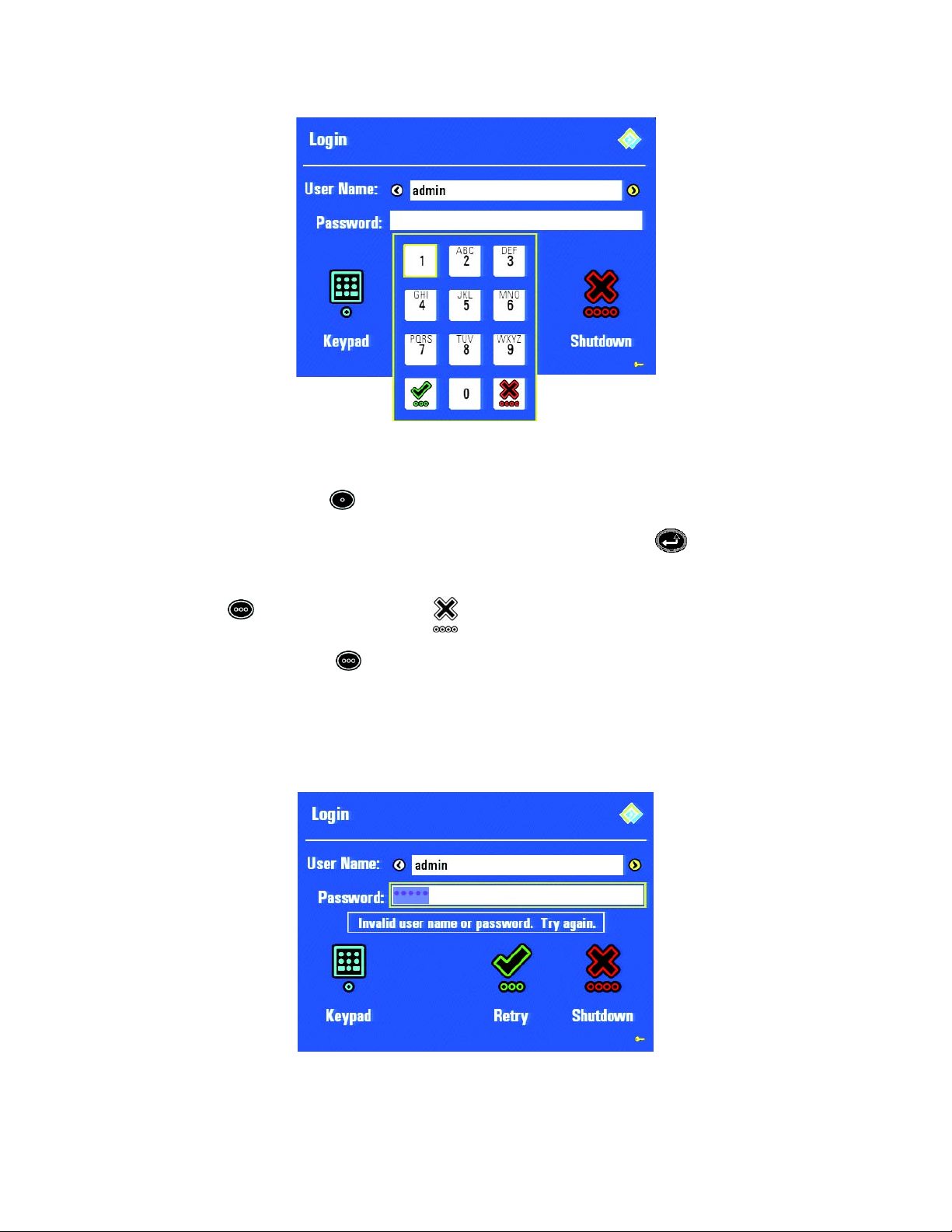
2. In the User Name list, turn the jog (inner dial) on the Control Pad to select the user name.
Figure 2. Login Dialog Box With On-Screen Keyboard
3. To enter the password, do the following:
a. On the Control Pad, press . The on-screen keyboard appears. (Figure 2)
b. Use the joystick to navigate to the first number your password, and then press Enter/Shift on the Control Pad.
c. Repeat these steps until you have entered the entire password.
d. Press to accept the password, or press to cancel the password and return to the Login dialog box.
4. From the Login dialog box, press to accept the user name and password. If the password is correct, the DVR5100 displays the main
application window. If the password is incorrect, follow the instructions below to re-enter your password.
RE-ENTERING LOGIN INFORMATION
If you enter an incorrect password on the Login dialog box, a message appears asking you to try again.
Figure 3. Retry Login Dialog Box
10 C1696M (8/06)
To re-enter your login information:
TIP: You can use an optional KBD5000 keyboard or a USB PC keyboard and mouse to perform some setup tasks more easily. Refer to
Understanding DVR Controls and Menus on page 13 for a comparison on using any of these devices to work with the on-screen menus.
1. Verify that the user name is correct, and then select a different user name if necessary.
2. To re-enter the password, do the following:
a. On the Control Pad, press . The on-screen keyboard appears. (Figure 2)
b. Use the joystick to navigate to the first number your password, and then press Enter/Shift on the Control Pad.
c. Repeat these steps until you have entered the entire password.
d. Press to accept the password, or press to cancel the password and return to the Login dialog box.
3. From the Login dialog box, press to accept the user name and password. If the password is correct, the DVR5100 displays the main
application window.
4. If re-entering your user name and password fails to start the application, contact your system administrator to verify that the user name and
password are still valid.
SHUTTING DOWN THE DVR5100
WARNING: Do not shut down the DVR5100 by turning off the power. Doing so can cause data loss or can corrupt the database. Always follow
the procedures in this section to turn off the unit.
To shut down the DVR5100:
TIP: You can use an optional KBD5000 keyboard or a USB PC keyboard and mouse to perform some setup tasks more easily. Refer to
Understanding DVR Controls and Menus on page 13 for a comparison on using any of these devices to work with the on-screen menus.
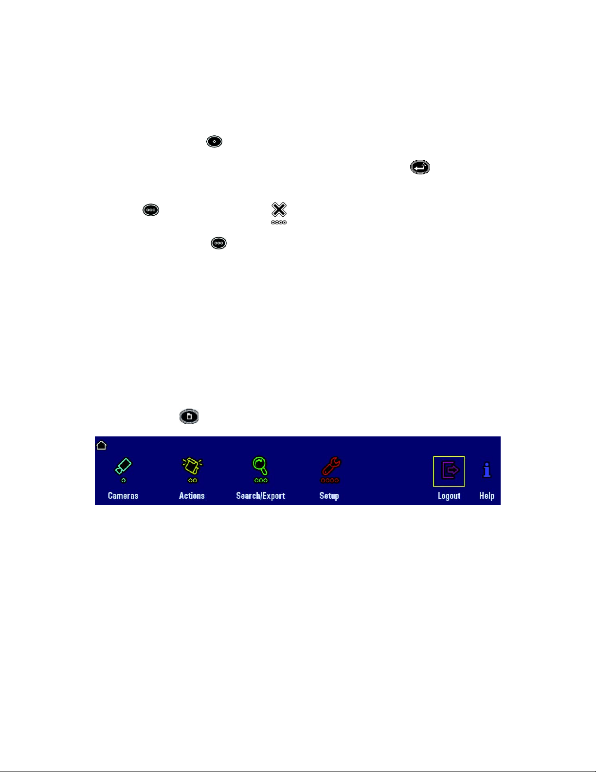
1. Press the Menu button to display the main menu.
Figure 4. Selecting Logout From the Main Menu
C1696M (8/06) 11

2. From the main menu, select the Logout icon. The Login dialog box appears.
Figure 5. Login Dialog Box
3. Select a user name, and then enter your password. You must select a user name that has administrator permissions.
4. Press the red function key , or navigate to Shutdown , and then press Enter/Shift . The DVR5100 saves all configuration
information and recorded video and then shuts down.
LOGGING OUT
You can log out of the system without shutting down the unit. Doing so avoids unauthorized access to the unit by someone who does not have a
user name and password.
To log out:
TIP: You can use an optional KBD5000 keyboard or a USB PC keyboard and mouse to perform some setup tasks more easily. Refer to
Understanding DVR Controls and Menus on page 13 for a comparison on using any of these devices to work with the on-screen menus.
1. From the main menu, select the Logout icon
2. Press Enter/Shift to accept the selection. The Login dialog box appears, and the system closes your worksession. Note that the
Login dialog box remains on the screen. You or another operator can log back on to the system from this dialog box.
Figure 6. Logging Out
12 C1696M (8/06)

Understanding DVR Controls and Menus
This section provides an overview of DVR5100 front panel controls and menus. The DVR5100 is a menu-driven DVR. You can operate the
DVR5100 using any of the following:
• DVR5100 Control Pad: The DVR5100 provides front panel controls that allow you to local access to the menu system. You can configure
and operate the DVR5100 using front panel controls. Refer to DVR5100 Control Pad on page 14 for a description of each key on the Control
Pad.
• Optional KBD5000 keyboard: The DVR5100 supports the KBD5000 keyboard. Refer to Navigating Through Menus with the KBD5000 Key-
board on page 16for a description of each key on the KBD5000 keyboard with the DVR5100.
• Optional PC USB keyboard and mouse: The DVR5100 provides three USB ports, which can be used to connect an optional PC keyboard
and mouse. Refer to Navigating Through Menus with a PC Keyboard and Mouse on page 18 for a description of using a PC keyboard and
mouse with the DVR5100.
• DVR5100 Remote Client: The DVR5100 allows you to use the DVR5100 Remote Client application to access the DVR5100 over the net-
work. The DVR5100 Remote Client application allows you access to advanced DVR5100 features and functionality. Refer to the DVR5100
Remote Client Operation Manual for more information.
FRONT PANEL INDICATORS
The following figure shows the DVR5100 front panel.
The front panel of the DVR5100 contains the following controls and indicators:
Pelco badge (power indicator) : The Pelco badge, on the left side of the unit, glows blue when the unit has power.
Behind the front bezel, the power indicator LED is white.
Figure 7. DVR5100 Front Panel Indicators
Table B. Features of the DVR5100 Front Panel
DVD: DVD drive that allows you to import/export video to and from the DVR and load install DVR software updates.
USB port: Version 2.0 USB port.
Control pad: Controls the basic operations of the unit. For information about the Control Pad, refer to DVR5100 Control Pad on
page 14.
Hard disk drive indicator : The hard disk drive (HDD) status indicator flashes yellow when there is HDD activity.
Network activity indicator : The activity indicator flashes green when the unit is sending or receiving network data.
C1696M (8/06) 13

Power key : Use the power key to turn the unit on and off.
Network status indicator : The network status LED indicates the network connection and speed. It may display one of
the following conditions:
• Off: The unit is not connected to the network.
• Solid Green: The unit is connected to the network using the 1000BaseT standard.
• Solid Amber: The unit is connected to the network using the 100BaseT standard.
• Solid Red: The unit is connected to the network using the 10BaseT standard.
Unit status indicator : The unit status is indicated by one of the following three colors:
• Green: The unit is functioning normally.
• Amber: The unit is in configuration mode.
• Red: The unit is in an error condition.
The Configuration/Reset key on the front panel is reserved for future use.
DVR5100 CONTROL PAD
The DVR5100 Control Pad allows you to configure and operate the DVR.
Table B. Features of the DVR5100 Front Panel (Continued)
Figure 8. DVR5100 Control Pad
The Control Pad contains the following keys and functions.
Table C. DVR5100 Control Pad Functions
Yellow function key:
• When on-screen menus are displayed, pressing the yellow key selects the yellow menu item.
• When on-screen menus are not displayed, pressing this key switches the DVR mode to live view.
Blue function key:
• At the Login dialog box, pressing this key displays the Keypad.
• When on-screen menus are displayed, pressing this key selects the blue menu item.
• When on-screen menus are not displayed, pressing this key displays the Quick Export dialog box.
14 C1696M (8/06)

Table C. DVR5100 Control Pad Functions (Continued)
Joystick: The joystick navigates to a video pane, menu item, or field. In PTZ mode, controls pan and tilt.
Quick export label: Indicates the function of this key when on-screen menus are not displayed.
Enter/Shift: The Enter/Shift key selects menu items when menus are visible. Press and release the key to enter or exit
PTZ mode, which is indicated by a blue border around the video pane. Press and hold the key to adjust volume.
Plus (+)/Minus (–) keys: Plus / Minus keys perform multiple actions and work in combination with the Enter/
Shift key.
• Viewing live video: The Plus key displays the next camera in the sequence in the currently selected video pane.
The Minus key selects the previous camera.
• PTZ mode: The Plus key zooms in. The Minus key zooms out.
• In a menu dialog box: The Plus key increases the value of a number field. The Minus key decreases the value
of a number field.
• With Enter/Shift key: The Plus key advances to the next camera page (for example, in 2x2 or quad view mode, it
shows the next four cameras). The Minus key returns to the previous camera page (for example, in 2x2 or quad view
mode, it shows the previous four cameras).
Go to live label: Indicates function of this key when on-screen menus are not displayed.
Menu: The Menu key shows or hides on-screen menus.
Play/pause label: Indicates function of this key when on-screen menus are not displayed.
Change layout label: Indicates function of this key when on-screen menus are not displayed.
Green function key:
• If the Keypad is displayed, pressing the green key closes the Keypad and selects the Password field. Pressing the green
key a second time logs on the user to the DVR5100 if the password was correct.
• When on-screen menus are displayed, pressing the green key selects the green menu item.
• When on-screen menus are not displayed, pressing this key toggles the DVR mode between play and pause.
Red function key:
• If the Keypad is displayed, pressing the red key closes the Keypad, deletes the contents in the Password field, and selects
the User Name field.
• When on-screen menus are displayed, pressing the red key selects the red menu item.
• When on-screen menus are not displayed, pressing this key repeatedly changes the video view from the single, 2x2, 3x3,
and 4x4 display layouts.
Jog control: The jog control performs the following functions:
• Frame-by-frame action: Turn the jog clockwise to advance frame by frame.
• With Enter/Shift key: Turn the jog counterclockwise to lower volume. Turn the jog clockwise to increase volume.
Jog shuttle: Turn the jog shuttle counterclockwise for fast rewind, clockwise for fast forward. To increase speed, turn
it several times.
C1696M (8/06) 15

NAVIGATING THROUGH MENUS WITH THE KBD5000 KEYBOARD
The KBD5000 keyboard controls serve different purposes depending on which part of the menus you are using. The keys light up to indicate
which controls are available based on your currently active operation. If a key is not lit, that control is not currently available.
ACTIVATING ON-SCREEN MENUS
When you want to activate on-screen menus, you can use the keys on the KBD5000. The menu operations are described in the following table:
Table D. KBD5000 Menu Operations
Joystick Module
Key Menu Operations
Joystick: Moves left and right through the main menu, between tabs on the configuration screens, moves between items in
a dialog box, expands lists like the Devices list on the Devices tab of the Configuration screen.
Joystick trigger: Selects menu items. Performs the same actions as the Enter/Shift key on the DVR5100 Control
Pad.
Help key: Displays or hides context-sensitive help for the KBD5000 keyboard.
Keypad Module
Key Menu Operations
Alphanumeric keypad: The keys on the alphanumeric keypad are not used. You must enter text from the on-screen
keyboard.
Camera selection key: Displays the Select Cameras dialog box with list of cameras.
Monitor selection key: This key is not used.
Jog/Shuttle Module
Key Menu Operations
Shuttle (outer ring): Backs up to a higher-level menu. Expands a level in a hierarchy.
Jog (inner dial): Moves up and down through a list.
Color-coded function keys: Selects one of the on-screen menu options. Keys are context sensitive.
Menu selection key: Shows or hides the previously displayed DVR5100 menu.
16 C1696M (8/06)

ACTIVATING LIVE AND PLAYBACK CONTROLS
After you select a video pane, you can work with the live or recorded video, operate pan and tilt commands, or initiate other camera-specific
actions with the KBD5000 keys. The menu operations are described in the following table:
Table E. KBD5000 Live and Playback Operations
Joystick Module
Key Live and Playback Operations
Joystick: Navigates up and down, left and right across the monitor and across menus. Controls PTZ. Adjusts focus and iris:
turn the handle right to focus closer or open the iris; turn it left to focus farther or close the iris.
Joystick trigger: Places the currently selected video pane into PTZ mode. Pressing it again removes the PTZ mode.
Help key: Displays or hides context-sensitive help about the KBD5000 keyboard.
Aux key: Activates the wiper command.
Iris key: Displays the dialog for adjusting iris on the currently selected camera.
Focus key: Displays the dialog for adjusting focus on the currently selected camera.
Keypad Module
Key Live and Playback Operations
Alphanumeric keypad: The keys on the keypad are not used by the DVR5100. You must enter text from the on-screen
keyboard.
Camera selection key: Displays the Select Camera dialog box with a list of cameras.
Monitor selection key: This key is not used.
Multiple view keys: Switches the monitor display to view 1, 4, 9, or 16 images.
C1696M (8/06) 17

Table E. KBD5000 Live and Playback Operations (Continued)
Jog/Shuttle Module
Key Live and Playback Operations
Menu selection key: Shows or hides the main menu.
Shuttle (outer ring): Performs fast rewind when moved to the left. Performs fast forward when moved to the right. When a
sub-menu is displayed, turning the shuttle to the left returns you to the main menu. While reviewing recorded video, turn the
shuttle to view the video up to 2x, 4x, 15x, 60x, or 300x of normal speed.
Jog (inner dial): Performs slow rewind when moved to the left. Performs slow forward when moved to the right. While
viewing recorded video, turn the jog counterclockwise to rewind video at a rate of ½ a second for each notch of the turn. To
advance recorded video frame by frame, turn the jog clockwise.
Color-coded function keys: Selects one of the options available on a menu.
Play/pause video key: Plays or pauses recorded video.
Record video key: Records video for export. While recording, pressing this key marks the video with a yellow bar.
Live/playback mode key: Stops playback and returns to live video for the currently selected camera.
NAVIGATING THROUGH MENUS WITH A PC KEYBOARD AND MOUSE
You can attach a USB PC keyboard and mouse to the DVR5100 in addition to using the control pad to navigate through menus. The keyboard and
mouse operations are described in the following table:
Table F. USB PC Keyboard and Mouse Operations
USB PC Keyboard
Key Menu Operations
Enter
F1 - F4 Perform the same actions as the four color-coded function keys on the DVR5100 Control Pad.
F5 - F8
F9
Tab or Shift + Tab
Esc (Escape)
Shift + (Plus)
Selects a menu item. Performs the same actions as the Enter/Shift key on the DVR5100
Control Pad.
Changes the screen layout from the single, 2x2, 3x3, and 4x4 display layouts respectively.
Displays the Camera Selection dialog box.
Moves to the next field or tab on a menu, or selects the next command on a dialog box or screen.
Press Shift+Tab to move to the previous field or tab on a menu.
Closes a menu.
In live view mode, displays the next camera in the currently selected video pane. In PTZ mode,
zooms in on the scene. In the menus, expands the device tree or increases a number in a text
field. While viewing recorded video, advances the video one frame at a time.
In live view mode, displays the previous camera in the currently selected video pane. In PTZ
- (Minus)
Down or Up Arrow
18 C1696M (8/06)
mode, zooms out of the scene. In the menus, closes the device tree or decreases a number in a
text field. While viewing recorded video, reverses the video one frame at a time.
In PTZ mode, tilts the currently selected camera down or up. In the menus, selects the next or
previous entry in a list on a menu or dialog box.

Table F. USB PC Keyboard and Mouse Operations (Continued)
Ctrl + Down Arrow/
Ctrl + Up Arrow
Right or Left Arrow
Ctrl + Right Arrow/
Ctrl + Left Arrow
Page Up or Page Down
Backspace
Alphanumeric keypad
<
>
L
M
P
R
S
X
Z
In the menus, increases or decreases the number in a field, or selects the next or previous entry
in a list.
In PTZ mode, pans the currently selected camera right or left. In the menus, moves to the next or
previous field on a menu or dialog box.
Increases or decreases the audio volume.
Scrolls forward or backward through the timeline on the Quick Search dialog box, or selects the
next or previous entry in a list on a menu or dialog box.
Returns to the previous menu; performs the same action as turning the shuttle
counterclockwise.
Use any alphanumeric key on the keyboard to enter information in a text field such as a
password, IP address, comment or other field. Do not enter characters that are not valid for the
currently selected field. Refer to the specific instructions for the field for guidelines on valid
entries. See the descriptions in this table for additional functions for specific characters.
Plays recorded video backwards.
Plays recorded video forwards.
Switches the currently selected video pane to live view mode.
Displays the main menu.
In live view mode, plays or pauses the video in the currently selected video pane.
In live view mode, starts recording video in the currently selected video pane.
Displays the Quick Search dialog box for the currently selected video pane.
Opens the Quick Export dialog box.
Switch to PTZ mode.
USB Mouse
Right-Click
Left-Click
Selects a menu icon, text field, or check box; executes a command key; and displays the next tab
on a configuration screen. Point and click on an up or down arrow next to a text field to increase
or decrease the number or to select the next or previous entry in a list.
Displays a shortcut menu if one is available. For example, right-click the device list on the
Devices tab to display a shortcut menu from which you can copy or paste device settings, delete
a selected device, hide offline devices from the list, restore factory defaults, and expand or
collapse the device tree.
Figure 9. Shortcut Menu Accessible From a Mouse
C1696M (8/06) 19

Overview of Navigation and Controls
The DVR5100 Series DVR provides semitransparent on-screen menus that allow you to adjust settings while continuing to monitor live video. The
DVR5100 Control Pad offers a quick and convenient set of local controls that allow you to configure and operate the DVR.
Figure 10. DVR5100 Main Window
The DVR5100 application window contains the following elements:
Icon path: Orients you to your location in the menu hierarchy.
Camera information: Displays the camera name and the date and time where that camera is located.
On-screen menus: Provide access to all operational functions through a hierarchical set of four-option menus. Large, color-coded
icons make it easy to view and make your selections.
Video pane: Displays video, either live from a camera or recorded from the hard disk of the unit. Displays up to 16 video streams at
one time, in any combination of live and recorded video.
Video pane border: Indicates status. Bright green indicates the currently active video pane. Red indicates that manual recording is
in progress. Yellow indicates that recorded video is being played back. Blue indicates that PTZ controls are active.
Context-sensitive help: Describes how to use the currently active function from the KBD5000 or how to use the front panel
controls on the DVR5100. Note that a different set of online help information appears depending on how you display the help. To
view the online help about the KBD5000, press the Help button on the keyboard. To display online help about the front panel
controls, select the Help icon from the main menu of the DVR5100. Figure 10 illustrates the online help for the KBD5000.
20 C1696M (8/06)

DISPLAYING AND HIDING THE SYSTEM MENUS
Press the Menu key to display and hide the on-screen menus.
The first time you display the menus, the DVR5100 displays the main menu. If you navigate to a lower-level menu and then close the menu
display, the DVR5100 retains that information and returns you to the same menu the next time you press the Menu key. To hide an on-screen
menu, press the Menu key again.
Figure 11. DVR5100 Main Menu
NAVIGATING TO AND SELECTING A MENU ITEM
There are three ways to navigate within a menu and select an item:
• Use the joystick to move between the on-screen icons.
• Press a function key that is identical in color to a menu item.
• Turn the jog (inner dial) of the jog/shuttle to move across a menu or up and down a list.
JOYSTICK
To navigate to and select a menu item:
1. Move the joystick left or right to a menu item. The yellow cursor denotes the highlighted menu item.
2. Press the Enter/Shift key to select the highlighted menu item. To return to a previous menu, move the joystick to the on-screen Back
icon , and then press the Enter/Shift key.
FUNCTION KEYS ON THE CONTROL PAD
The DVR5100 Control Pad contains four color-lit function keys. The color of each key corresponds to the color of its icons displayed on the
monitors linked to the DVR5100. This color-matching design lets you navigate the on-screen menus without looking down to read keyboard text
labels. The colors always appear in the same order from left to right: blue, yellow, green, and red.
Figure 12. Control Pad Color-Coded function keys
To navigate through the different levels in menus or to select an item:
1. Press the color-coded function key that corresponds to the on-screen menu item. For example, to select the blue icon on the screen, press
the blue function key on the front panel of the DVR5100.
2. To return to a previous menu, turn the jog shuttle to the left. After you make a selection, the DVR5100 presents a menu or displays a dialog.
C1696M (8/06) 21

USING THE JOG/SHUTTLE TO NAVIGATE THROUGH MENUS
There are two ways to return to a previous, or higher level, menu:
• Turn the jog (inner dial) to the right or left until you select the Back icon on the screen, and then press the
Enter/Shift key .
• Turn the shuttle (outer ring) counterclockwise.
The icon path at the top of the menu bar tells you which menu icons you selected to arrive at your current location. This lets you know how deep
within the menu structure you are and how many levels there are to reach the main menu. Most functions are no more than one or two levels
deep. For example, in the figure below, you would need to return one level to reach the main menu from the Search/Export menu.
Figure 13. Sample Icon Path
USING THE CONTROL PAD TO ENTER CHARACTERS
The DVR5100 can be configured and operated from the Control Pad, KBD5000 keyboard, USB PC keyboard, and Remote Client. This section
describes how to use the DVR5100 Control Pad to enter characters in text fields.
To enter characters using the Control Pad:
1. Select a field that supports character entry, for example a name field or IP address field.
2. Press the blue function key to display the on-screen keyboard.
Figure 14. On-Screen Keyboard
22 C1696M (8/06)

3. Enter characters by pressing the following keys:
• Turn the jog to the right or left to select a character of the name or IP address that you are entering.
• Use the joystick, blue function key, or yellow function key to move between characters within the text field.
• Use the jog/shuttle to move slowly or quickly through the list of characters.
• Press the Minus key to delete the previous character.
• Press the Plus key to insert a space.
• Press the Shift/Enter key to accept the currently selected command and return to navigating between fields on the Setup tab.
• Press the green function key to accept a completed entry.
• Press the red function key to cancel an entry and return to the previous dialog.
NOTE: You can use masks to select the set of characters appropriate for some text fields (e.g. 1–255 for IP addresses, A–Z, numbers, and special
characters for names).
SHOWING AND HIDING ONLINE HELP INFORMATION
For help with the system or to view system status, select the on-screen Help icon , and then press the blue function key to display online help,
or press the yellow function key to display system status.
Figure 15. Help Menu
If you choose to display online help, the following screen appears. Pressing any key hides this screen.
Figure 16. Online Help for the Control Pad
C1696M (8/06) 23

On-Screen Menus
The DVR5100 Series DVR on-screen menus hierarchy is designed to present only those menus for which you have permission. Depending on your
user role, you might see all available menus or only a few of the menus. There are user roles for an administrator, manager, operator, and guest.
The descriptions of menus in this section are based on the administrator role, which has access to all menus and functions. If you do not see a
menu to which you think you should have access, contact your system administrator to change the permissions for your user ID.
DVR5100 MAIN MENU
The main menu of the DVR5100 provides access to all daily operational functions. It is organized into four menus from which all other functions
are available.
CAMERAS MENU
The Cameras menu contains options that are related to selecting cameras to view in video panes. It also contains options for setting up and
adjusting cameras with the Focus and Iris commands, and for reviewing camera properties from the Camera Menu.
Figure 17. DVR5100 Main Menu
Figure 18. Cameras Menu
ACTIONS MENU
The Actions menu contains options for running scripts and relays on selected devices. To create scripts or relays, log on to a DVR5100 Remote
Client application. You can also control PTZ operations or auxiliary operations such running a wiper on compatible cameras.
Figure 19. Actions Menu
24 C1696M (8/06)

SEARCH/EXPORT MENU
The Search/Export menu contains options for locating and reviewing recorded video and for exporting snapshots and recorded video. To export
video you must have a CD or DVD available. To export snapshots, you must have a USB storage device attached to the DVR5100 or to the
KBD5000.
Figure 20. Search Export Menu
SETUP WINDOW
If you have permissions to do so, you can view or modify setup information for the DVR5100. The Setup window contains options for configuring
the following settings: System Configuration, Devices, Users, Monitors, and Recording Schedules. To set up roles, scripts, and events you must
log on to the DVR5100 Remote Client application.
Figure 21. Setup Window
C1696M (8/06) 25

Operating the DVR5100
The DVR5100 Control Pad provides access to most DVR5100 features and functionality. The DVR5100 Remote Client application is required to
configure certain options accessible to the DVR5100. For example, scripts are created using the Remote Client, but are operated on the DVR5100
from the Control Pad. An optional KBD5000 keyboard or USB PC keyboard and mouse also can be used to operate the DVR5100 instead of the
Control Pad. The instructions in this manual refer to the DVR5100 Control Pad. Refer to Understanding DVR Controls and Menus on page 13 for
alternate keystrokes if you any of these devices.
Monitoring Live Video
The DVR5100 starts up in live video mode. The following sections describe how to work in the live view mode:
• Selecting a Video Pane, below
• Changing Screen Layout, below
• Viewing a Specific Camera on page 27
• Moving Through the Camera Sequence on page 28
• Working With Cameras on page 29
SELECTING A VIDEO PANE
When you start the unit and are displaying a layout with several video panes, the upper left video pane is selected by default. To select a different video pane, use the joystick to move left, right, up, and down on the monitor.The border of the currently selected video pane changes color to
reflect the current operating state of the DVR5100.
• Green: Indicates the currently selected video pane.
• Yellow: Indicates that recorded video is being displayed in the video pane.
• Blue: Indicates that PTZ mode has been enabled in the video pane. Press Enter/Shift to enable PTZ mode. Refer to Reposition-
ing a Camera With PTZ Capabilities on page 32 for more information about working with PTZ cameras.
• Red: Indicates that manual recording is in progress in the video pane.
CHANGING SCREEN LAYOUT
Press the red function key on the Panel Keypad to display any of the four screen layouts. Each time you press the this key, the screen layout changes to one of the following layouts:
• Full-screen view (1x1): Displays a single video pane.
• Four-camera view (2x2): Displays four video panes in rows of two.
• Nine-camera view (3x3): Displays nine video panes in rows of three.
• Sixteen-Camera view (4x4): Displays 16 video panes in rows of four.
26 C1696M (8/06)

VIEWING A SPECIFIC CAMERA
When you select a camera, its video stream is sent to the video pane with the green border. For example, if your display is set to a 2x2 layout and
the upper left video pane is selected, you can select any camera to display in this video pane. Follow the instructions below to display video for a
specific camera in any video pane or to display a specific camera and switch to full-screen mode.
Figure 22. Displaying Video in a 2x2 Mode
To view a camera in a specific video pane:
NOTE: The instructions in this manual refer to the DVR5100 Control Pad. An optional KBD5000 keyboard or USB PC keyboard and mouse also can
be used to operate the DVR5100 instead of the Control Pad. Refer to Understanding DVR Controls and Menus on page 13 for alternate keystrokes
if you any of these devices.
1. In the live video mode, use the joystick to navigate to the selected video pane. A green border surrounds the video pane.
2. On the Panel Keypad, press Menu . The DVR5100 menu appears. The DVR5100 will display the last menu that was opened. In the
figure below, the main menu is shown.
Figure 23. Main Menu
3. Use the joystick or jog (inner dial) to navigate to the Cameras icon, and then press Enter/Shift . The Camera menu appears.
Figure 24. Camera Menu
C1696M (8/06) 27

4. If it is not already selected, navigate to the Select Camera icon, and then press Enter/Shift . The Camera List appears.
Figure 25. Camera List
5. Use the joystick or the jog (inner dial) to select a camera from the list, and then press Enter/Shift . Video from the camera is displayed
in the selected video pane.
NOTE: A red slash through a camera icon indicates that it is not currently available for display.
To display a specific camera in full-screen mode:
1. Navigate to the video pane displaying the desired camera.
2. Press the red function key until the display changes to a single pane.
MOVING THROUGH THE CAMERA SEQUENCE
Although a camera is displayed in a specific video pane, you can quickly cycle through the list of cameras in sequence.
To sequence through the list of cameras:
NOTE: The instructions in this manual refer to the DVR5100 Control Pad. An optional KBD5000 keyboard or USB PC keyboard and mouse also can
be used to operate the DVR5100 instead of the Control Pad. Refer to Understanding DVR Controls and Menus on page 13 for alternate keystrokes
if you any of these devices.
1. In the live video mode, use the joystick to select a video pane. A green border surrounds the video pane.
Figure 26. Displaying a Camera in a Video Pane
2. On the Panel Keypad, press Plus to view the next camera in the sequence in the video pane. To view video for the previous camera in
the list, press Minus .
28 C1696M (8/06)

WORKING WITH CAMERAS
This section describes how to work with cameras that are attached to the DVR5100 and is organized into the following topics:
• Adjusting the Iris, below
• Adjust the Focus on page 31
• Repositioning a Camera With PTZ Capabilities on page 32
• Accessing Camera Menus on page 33
ADJUSTING THE IRIS
NOTE: The instructions in this manual refer to the DVR5100 Control Pad. An optional KBD5000 keyboard or USB PC keyboard and mouse also can
be used to operate the DVR5100 instead of the Control Pad. Refer to Understanding DVR Controls and Menus on page 13 for alternate keystrokes
if you any of these devices.
To adjust iris:
1. In the live view mode, use the joystick to select a video pane that is displaying video from a camera whose iris requires adjustment. Refer
to Viewing a Specific Camera on page 27 for instructions on displaying a camera. The selected pane is highlighted by a green border.
Figure 27. Camera List
2. Press Menu . The Select Camera menu appears.
Figure 28. Select Camera Menu
C1696M (8/06) 29

3. Press the red function key to select the Iris icon. The Iris dialog box appears.
Figure 29. Iris Dialog Box
4. Navigate to the option box. By default, the iris mode is set to Auto Iris On.
5. Turn the jog (inner dial) to set the iris mode to Auto Iris Off.
6. Navigate to the iris –/+ controls, and then do one of the following:
• To open the iris, turn the shuttle clockwise. As an alternative, press and hold the Plus button to open the iris until it
reaches its limit.
Figure 30. Open Iris Control
• To close the iris, turn the shuttle counterclockwise. As an alternative, press and hold the Minus button to close the iris
until it reaches its limit.
Figure 31. Close Iris Control
7. Press the green function key to close the Iris dialog box.
30 C1696M (8/06)

ADJUST THE FOCUS
NOTE: The instructions in this manual refer to the DVR5100 Control Pad. An optional KBD5000 keyboard or USB PC keyboard and mouse also can
be used to operate the DVR5100 instead of the Control Pad. Refer to Understanding DVR Controls and Menus on page 13 for alternate keystrokes
if you any of these devices.
To adjust focus:
1. In the live view mode, use the joystick to select a video pane that is displaying video from a camera whose iris requires adjustment. Refer
to Viewing a Specific Camera on page 27 for instructions on displaying a camera. The selected pane is highlighted by a green border.
2. Press Menu . The Select Camera menu appears.
Figure 32. Select Camera Menu
3. Press the red function key to select the Focus icon. The Focus dialog box appears.
Figure 33. Focus Dialog Box
4. Navigate to the option box. By default, the focus mode is set to Auto Focus On.
5. Turn the jog (inner dial) to set the focus mode to Auto Focus Off.
C1696M (8/06) 31

6. Move to the focus –/+ control and do one of the following:
• To focus closer to an object, turn the shuttle (outer dial) to the right. The plus sign (+) is highlighted by a circle, indicating the
direction of the change. As an alternative, press and hold the Plus button to focus closer.
Figure 34. Focus Closer to An Object
• To focus farther away from an object, turn the shuttle (outer dial) to the left. The minus sign (-) is highlighted by a circle, indicat-
ing the direction of the change. As an alternative, press and hold the Minus button to focus farther away.
Figure 35. Focus Farther Away From an Object
7. Press to close the Focus dialog box.
REPOSITIONING A CAMERA WITH PTZ CAPABILITIES
If you select a camera that supports pan, tilt, and zoom operations, you can reposition the camera with the joystick. PTZ cameras can be
repositioned to view a wider scene, to view a tighter scene, or to view a scene in a different direction. To enter PTZ mode, the on-screen menus
must be turned off. While in PTZ mode, it is not possible to navigate the on-screen menus. A blue border surrounds the video pane when PTZ
mode is on. In addition to controlling a PTZ camera manually from the front panel controls, you can reposition the camera based on predefined
patterns, presets, and scan operations. Refer to Using Patterns, Presets, and Scans on page 42 for more information.
To reposition a camera with the front panel controls:
NOTE: The instructions in this manual refer to the DVR5100 Control Pad. An optional KBD5000 keyboard or USB PC keyboard and mouse also can
be used to operate the DVR5100 instead of the Control Pad. Refer to Understanding DVR Controls and Menus on page 13 for alternate keystrokes
if you any of these devices.
1. In the live view mode, navigate to a video pane. The selected video pane is surrounded by a green border.
2. On the front panel controls, press Enter/Shift . The border around the video pane changes to blue.
Figure 36. PTZ Mode Indicated by Blue Border
32 C1696M (8/06)

3. Move the joystick left or right to pan to the left or right of the current scene.
4. Move the joystick up or down to tilt the camera up or down from the current scene.
5. Press and hold the Plus or Minus buttons to zoom in and zoom out of the scene.
If the camera does not respond to the joystick, verify that the camera protocol is configured correctly. The DVR5100 supports Coaxitron, Extended
Coaxitron, Pelco D and Pelco P protocols for cameras that are equipped for PTZ control.
ACCESSING CAMERA MENUS
Many settings for different cameras can be programmed to fit your specific needs. You can display menus and adjust camera settings from the
DVR5100 if your user role has permissions to do so. Although you can program patterns and presets from some camera menus, for best results
use the DVR5100 Remote Client Application to program these operations.
WARNING: Among the available menu options are commands to restart or turn off a camera. Restarting or turning off a camera stops any
video recording that might be in progress for the camera. Check with your system administrator before you restart or turn off a camera that
might be in use by other users on the system.
NOTE: The instructions in this manual refer to the DVR5100 Control Pad. An optional KBD5000 keyboard or USB PC keyboard and mouse also can
be used to operate the DVR5100 instead of the Control Pad. Refer to Understanding DVR Controls and Menus on page 13 for alternate keystrokes
if you any of these devices.
To access a camera menu:
1. In the live view mode, select a video pane that is displaying a camera for which you want to view its on-screen menu. Refer to Viewing a
Specific Camera on page 27.
The border of the video pane will be green. If the border is blue, you cannot access the camera menu. Press Enter/Shift to change the
mode from PTZ mode to live view mode.
2. Press Menu . A DVR5100 menu appears.
Figure 37. Selecting the Camera Menu
3. Navigate to the Cameras menu from the main menu, and then select the Camera Menu icon. The settings menu for the camera appears.
The list of options varies for each camera type. For example, the Figure 38 shows the main menu for a typical camera.
MAIN MENU
<LANGUAGE>
<CAMERA>
<POWER UP>
<LINE SYNC>
<ZONES>
<WINDOW BLANKING>
<ALARMS>
<AUX>
<TITLE TEXT>
<ALERT>
<CLEAR>
<PASSWORD>
BACK
EXIT
Figure 38. Example of a Camera Settings Menu
C1696M (8/06) 33

4. Navigate the menu as follows:
• Use the joystick to move through the list of menu options and through the list of settings for each option.
• Press Enter/Shift to select or accept an option or a setting. You cannot undo a change once you have pressed this button.
• To return to a previous menu in the Camera Settings menu, move to the Back command, and then press Enter/Shift .
5. After you have completed modifying camera settings, move to the Exit command, and then press Enter/Shift . The camera menu
disappears from the monitor.
ADJUSTING AUDIO
NOTE: The instructions in this manual refer to the DVR5100 Control Pad. An optional KBD5000 keyboard or USB PC keyboard and mouse also can
be used to operate the DVR5100 instead of the Control Pad. Refer to Understanding DVR Controls and Menus on page 13 for alternate keystrokes
if you any of these devices.
To adjust the audio level:
1. Select a video pane, and then press and hold Enter/Shift .
2. While holding Enter/Shift , turn the jog (inner dial) to the right to raise the audio level. To lower the audio level, turn the jog (inner
dial) to the left.
34 C1696M (8/06)

Responding to Alarms
Each time an alarm occurs, the DVR5100 displays an Alarm Received dialog box, which allows you to respond immediately to the event or elect
to have the alarm event snoozed for a specified amount of time. An alarm event must be acknowledged before it will disappear from the screen.
Any user with permissions to do so can respond to an alarm event. The alarm message might provide instructions on how to respond to the alarm
event. If the alarm event meets certain criteria, an e-mail might be sent to designated staff. To set up automatic e-mail notification, you must
create a script to do so, and your system must have a mail server configured. Contact your system administrator to verify that your system is
configured to send automatic e-mail messages about alarms.
Figure 39. Acknowledging an Alarm
ACKNOWLEDGING AN ALARM EVENT
The DVR5100 provides a message that can instruct you on how to respond to certain alarm events. If there are several alarms displayed on the
Alarm Received dialog box (Figure 39), you can acknowledge all alarms at the same time. By default, all new alarms are selected at the same
time. Selecting the Ack icon acknowledges all alarms. Note that you must select a single alarm if you want to review its comments. Turn the jog
(inner dial) to select a single alarm if you want to review its comments.
NOTE: The instructions in this manual refer to the DVR5100 Control Pad. An optional KBD5000 keyboard or USB PC keyboard and mouse also can
be used to operate the DVR5100 instead of the Control Pad. Refer to Understanding DVR Controls and Menus on page 13 for alternate keystrokes
if you any of these devices.
C1696M (8/06) 35

To acknowledge an alarm event:
1. After an alarm message appears on the Alarm Received dialog box (Figure 39), press the blue function key to display the comments
associated with the alarm. If necessary, turn the jog (inner dial) to select a single alarm. Instructions appear on how to respond to the
alarm.
Figure 40. Alarm Information
2. Select the OK icon , and then press Enter/Shift , or press the green function key to close the comments. The Alarm
Received dialog box appears. (Figure 39)
3. Do one of the following:
• Navigate to the Ack icon , and then press Enter/Shift . The Alarm Received dialog box is closed and the acknowledge
action is recorded in the system log. As an alternative, you can press the green function key to acknowledge the alarm.
• Navigate to the Snooze icon , and then press Enter/Shift . The alarm will reappear after the snooze time has expired. As an
alternative, press the red function key to snooze the alarm.
REQUESTING A REMINDER FOR AN ALARM EVENT
With the DVR5100 you can postpone responses to an alarm event for a specified time period. Referred to as “snooze,” the alarm is redisplayed
after the snooze time expires.
NOTE: The instructions in this manual refer to the DVR5100 Control Pad. An optional KBD5000 keyboard or USB PC keyboard and mouse also can
be used to operate the DVR5100 instead of the Control Pad. Refer to Understanding DVR Controls and Menus on page 13 for alternate keystrokes
if you any of these devices.
To request a reminder for an alarm event:
1. While the Alarm Received dialog box (Figure 39) is displayed, select an alarm.
2. Use the joystick to select the Snooze icon , and then press Enter/Shift , or press the red function key . The Alarm Received
dialog box is closed and the snooze action is recorded in the system log. After a delay, the alarm notification reappears with a clock icon
indicating that the alarm was previously snoozed.
36 C1696M (8/06)

VIEWING COMMENTS
NOTE: The instructions in this manual refer to the DVR5100 Control Pad. An optional KBD5000 keyboard or USB PC keyboard and mouse also can
be used to operate the DVR5100 instead of the Control Pad. Refer to Understanding DVR Controls and Menus on page 13 for alternate keystrokes
if you any of these devices.
To view an alarm message comment:
1. On the Panel Keypad, press the blue function key .
2. An alarm message appears.
3. Review the comments about the alarm, and then press the red function key when you are done.
C1696M (8/06) 37

Executing Scripts
A script is like a macro but provides much more power and flexibility. Scripts may be used to control almost all system functions and may be
combined in almost any order. To create a script you must be logged on to the DVR5100 remote client application. Refer to the operation manual
for the remote client application for instructions on creating scripts. The following table describes actions that are supported in scripts.
Action Has the following effect
Display video Displays video from the indicated camera.
Start Recording Starts recording video from the indicated video source.
Run Script Initiates execution of a remote script.
Wait Pauses execution of a script for a given number of seconds.
Send Mail Sends an e-mail message to a given recipient.
Activates Relay Activates a relay device.
Preset Moves camera to a specified preset. A preset allows you to direct a PTZ (camera positioning system) on a predetermined
location.
Pattern Runs a specified pattern on a camera. A pattern allows you to program the movements of PTZ-enabled cameras.
Table G. Supported DVR5100 Scripts
Start Loop Starts a specific sequence of commands within the script.
End Loop Ends a specific sequence of commands within the script.
Stop Pattern Stops a pattern.
WORKING WITH SCRIPTS
NOTE: The instructions in this manual refer to the DVR5100 Control Pad. An optional KBD5000 keyboard or USB PC keyboard and mouse also can
be used to operate the DVR5100 instead of the Control Pad. Refer to Understanding DVR Controls and Menus on page 13 for alternate keystrokes
if you any of these devices.
To start or stop a script from the menus:
1. From the main menu, select Actions.
2. Select Scripts.
Figure 41. Selecting Actions on DVR5100 Main Menu
Figure 42. Selecting Scripts on Actions Menu
38 C1696M (8/06)

3. When the Execute Script dialog box appears, turn the jog (inner dial) to scroll through and select a script from the list (Figure 43).
4. Press the buttons on the Panel Keypad as follows:
• To start a script, press the green function key , or use the joystick to navigate to the Execute icon , and then press Enter/
Shift .
• To stop a script, press the yellow function key , or use the joystick to navigate to the Halt icon , and then press Enter/
Shift . Note that the Halt icon is available only when a script is running.
• To close the dialog box without running a script, press the red function key , or navigate to the Cancel icon , and then
press Enter/Shift .
Figure 43. Execute Script Dialog Box
C1696M (8/06) 39

Activating Relays
The DVR5100 may be used to activate relay output manually, connecting DVR5100 devices to other external devices. A relay may be activated for
a predetermined period of time (the dwell time) or may remain latched until there is another signal to release the relay.
Users with administrator permissions can configure relays from the Devices tab in the Setup window.
NOTE: The instructions in this manual refer to the DVR5100 Control Pad. An optional KBD5000 keyboard or USB PC keyboard and mouse also can
be used to operate the DVR5100 instead of the Control Pad. Refer to Understanding DVR Controls and Menus on page 13 for alternate keystrokes
if you any of these devices.
To activate a relay:
1. From the main menu, select Actions. The Actions menu appears.
2. Navigate to Relays, and then press Enter/Shift . The Activate Relays dialog box appears.
Figure 44. Actions Menu
Figure 45. Activating a Relay
3. Turn the jog (inner dial) to select a relay from the list.
4. Navigate to the Activate icon , and then press Enter/Shift . To cancel the selection without activating the relay, navigate to the
Cancel icon , and then press Enter/Shift , The Execute Relays dialog box appears. If there are no relays available on your
system, the following message appears.
40 C1696M (8/06)

Figure 46. DVR5100 Dialog Box
C1696M (8/06) 41

Using Patterns, Presets, and Scans
With the DVR5100 you can activate patterns, presets, and scans. A pattern is a user-defined, viewable camera path with a beginning and end.
The number and duration of patterns varies with different positioning systems. A preset action forces a camera with PTZ capability (pan, tilt, and
zoom) to reposition itself on a specific scene, such as a door. A scan action moves a camera across the current scene that it is viewing from a
predetermined starting point. For a description of the types of scan actions you can perform, refer to Activating Scans on page 44.
Patterns, presets and scans can be activated automatically or manually from the DVR5100. Patterns and presets must be pre-programmed from
the DVR5100 Remote Client application. A user must have administrator permissions to program the movements of PTZ cameras and to automate
other system activities in response to alarms or other events.
This section describes how to operate the DVR5100 to run patterns, presets, and scans and is organized into the following topics:
• Activating PTZ Patterns, below
• Stopping a Pattern on page 43
• Activating Presets on page 43
• Activating Scans on page 44
ACTIVATING PTZ PATTERNS
A pattern is a user-defined, viewable camera path with a beginning and end. The number and duration of patterns varies with different positioning systems.
NOTE: The instructions in this manual refer to the DVR5100 Control Pad. An optional KBD5000 keyboard or USB PC keyboard and mouse also can
be used to operate the DVR5100 instead of the Control Pad. Refer to Understanding DVR Controls and Menus on page 13 for alternate keystrokes
if you any of these devices.
To activate a pattern:
1. From the main menu, select Actions. The Actions menu appears.
Figure 47. Actions Menu
2. Navigate to PTZ Operations, and then press Enter/Shift . The PTZ Operations dialog box appears.
Figure 48. PTZ Operations Dialog Box
3. On the Panel Keypad press or until the pattern number appears in the text field.
4. Press the blue function key . The pattern starts. To exit the dialog box without activating the pattern, press the red function key .
42 C1696M (8/06)

STOPPING A PATTERN
NOTE: The instructions in this manual refer to the DVR5100 Control Pad. An optional KBD5000 keyboard or USB PC keyboard and mouse also can
be used to operate the DVR5100 instead of the Control Pad. Refer to Understanding DVR Controls and Menus on page 13 for alternate keystrokes
if you any of these devices.
To stop a pattern:
1. Select the video pane that is displaying video from a camera running a PTZ pattern.
2. If the border of the selected video pane is green, Press Enter/Shift . The border color changes to blue.
3. Move the joystick any direction. The pattern stops.
ACTIVATING PRESETS
A preset action forces a camera with PTZ capability (pan, tilt, and zoom) to reposition itself on a specific scene, such as a door. Preset actions are
activated automatically or manually from the DVR5100. A preset action is activated automatically when an alarm occurs that triggers the preset
action. For example, an alarm sounds on an exterior door to a building and the preset action is set to refocus a camera on that doorway. A manual
activation of a preset occurs when an operator selects a preset command from the Actions menu. For example, an operator is viewing video from
a fixed camera in a parking lot when he or she decides to refocus the camera on the doorway to get a better view of someone who is walking
toward the door.
A user with administrator-level permissions must program these actions in advance. Preset actions must be programmed using the Remote Client
application before they can be activated manually from the DVR5100. In addition to moving the camera to a predetermined scene, a descriptive
title can appear on the video pane. The type of camera positioning system determines the number of preset actions that are available.
Your cameras might provide predefined presets. Refer to the documentation for your cameras to determine which predefined presets are available, and then enter their numbers in the instructions below when you need to run them. For example, Pelco cameras use the Preset 95 to display
camera menus on a monitor.
To create preset actions, access the menu of the camera for which you want to create a preset action. Refer to Accessing Camera Menus on
page 33 for more information.
NOTE: The instructions in this manual refer to the DVR5100 Control Pad. An optional KBD5000 keyboard or USB PC keyboard and mouse also can
be used to operate the DVR5100 instead of the Control Pad. Refer to Understanding DVR Controls and Menus on page 13 for alternate keystrokes
if you any of these devices.
To activate a preset:
1. While in live view mode, select a video pane that is displaying video from a camera with PTZ capabilities. The video pane border is green.
2. From the main menu, select Actions, and then press Enter/Shift . The Action menu appears.
Figure 49. Scripts Menu
3. Select PTZ Operations, and then press Enter/Shift , The PTZ Operations dialog box appears.
Figure 50. PTZ Operations Dialog Box
C1696M (8/06) 43

4. On the Panel Keypad press or until the preset number appears in the text field, and then press the yellow function key . The
camera is moved to the preset location. To cancel your selection without activating the preset, press the red function key .
ACTIVATING SCANS
To scan is to view an area by panning a camera horizontally to the right or left. There are three types of scans available:
• Scan Random: A random scan occurs when the camera pans in an irregular, unsystematic pattern.
• Scan Frame: A frame scan occurs when the camera is repositioned for a three-second interval scan followed by a three-second pause.
• Scan Auto: An auto scan occurs by panning a camera continuously to the left or right.
Your cameras might provide predefined scans. Refer to the documentation for your cameras to determine which predefined scans are available,
and then enter their numbers in the instructions below when you need to run them.
NOTE: The instructions in this manual refer to the DVR5100 Control Pad. An optional KBD5000 keyboard or USB PC keyboard and mouse also can
be used to operate the DVR5100 instead of the Control Pad. Refer to Understanding DVR Controls and Menus on page 13 for alternate keystrokes
if you any of these devices.
To activate scanning:
1. While in live view mode, select a video pane that is displaying video from a camera with PTZ capabilities. The video pane border is green.
2. From the main menu, select Actions, and then press Enter/Shift . The Action menu appears.
Figure 51. Scripts Menu
3. Select PTZ Operations, and then press Enter/Shift , The PTZ Operations dialog box appears.
Figure 52. PTZ Operations Dialog Box
4. On the Panel Keypad press or until the scan number appears in the text field, and then press the yellow function key . The
camera scans according to the actions. To cancel your selection without activating the scan, press the red function key .
44 C1696M (8/06)

Activating Auxiliary Commands (Wiper)
On cameras that are equipped with a wiper, a preset command is available to activate it from the DVR5100. The DVR5100 ignores the command
if a camera does not support it.
NOTE: The instructions in this manual refer to the DVR5100 Control Pad. An optional KBD5000 keyboard or USB PC keyboard and mouse also can
be used to operate the DVR5100 instead of the Control Pad. Refer to Understanding DVR Controls and Menus on page 13 for alternate keystrokes
if you any of these devices.
To activate the wiper command:
1. While in live view mode, select a video pane that is displaying video from a camera with a wiper. The video pane border is green.
2. From the main menu, select Actions, and then press Enter/Shift . The Action menu appears.
Figure 53. Scripts Menu
3. Select Auxiliary, and then press Enter/Shift .
4. Repeat the command as often as necessary. The command is ignored on cameras that do not have a wiper.
C1696M (8/06) 45

Searching for Video
The DVR5100 offers two options for searching for recorded video:
• Quick Search: With Quick Search you can search for video for the currently selected camera.
• Enhanced Search: With Enhanced Search you can search for video on multiple cameras and for any available date and time range. An
enhanced search can be refined to include only specific events or recording types on specific cameras.
QUICK SEARCH
The Quick Search function provides a simple interface for selecting a time within the past 24 hours of the recorded video you want to view. This
section describes how to use the Quick Search feature.
Figure 54. Quick Search Dialog Box
The Quick Search dialog box contains the following commands and features:
• Timeline: Units of time increase or decrease between months and days, days and hours, hours and minutes, or minutes and seconds.
The Panel Keypad shuttle is used to change units as follows:
– Zoom in: Turn the shuttle clockwise to display a smaller unit of time.
– Zoom out: Turn the shuttle counterclockwise to display a larger unit of time.
Along with stars that indicate a marked event, the graphical indicator for recorded video represents recorded video with four different
colored bars:
• Green: Continuous recording
• Red: Alarm recording
• Blue: Motion recording
• Yellow: Manual recording
You turn the jog (inner dial) to the right or left to move forward or backward along the timeline.
• Play : Starts playing back the video from the position of the cursor along the timeline. The time and date are displayed above
the timeline.
• Lock : Displays the Lock Clip dialog box on which you can specify the date and time for which you want to lock a video clip.
• OK : Accepts the selected date and time. The recorded video clip is displayed in the currently selected video pane.
• Cancel : Rejects the selected date and time. No recorded video clip is displayed in the currently selected video pane.
46 C1696M (8/06)

PERFORMING A QUICK SEARCH
NOTE: The instructions in this manual refer to the DVR5100 Control Pad. An optional KBD5000 keyboard or USB PC keyboard and mouse also can
be used to operate the DVR5100 instead of the Control Pad. Refer to Understanding DVR Controls and Menus on page 13 for alternate keystrokes
if you any of these devices.
To perform a quick search for and play back video:
1. In the live view mode, select a video pane that is displaying video from a camera. The video pane border is green.
2. From the main menu, select Search/Export. The Search/Export menu appears.
Figure 55. Quick Search Menu
3. Select Quick Search, and then press Enter/Shift , The Quick Search dialog box appears (Figure 54).
4. Turn the jog (inner dial) to select the starting time along the timeline. To change the timeline display, turn the shuttle (outer dial) to zoom in
and out on the timeline. Units of time increase or decrease between months and days, days and hours, hours and minutes, or minutes and
seconds.
5. Do the following:
• To play video and keep the Quick Search dialog open, navigate to the Play icon , and then press Enter/Shift .
• To play video and close the Quick Search dialog, navigate to the OK icon , and then press Enter/Shift .
• To close the Quick Search dialog, navigate to the Cancel icon , and then press Enter/Shift .
For information about locking video from the Quick Search dialog box, refer to Locking and Unlocking a Video Clip on page 53.
C1696M (8/06) 47

ENHANCED SEARCH
You can use the Enhanced Search dialog box to search for recorded video based on the following search criteria:
• Date and time ranges: Search for video recorded in the following time periods:
– Yesterday: Searches the previous 24-hour period from the current date.
– Past 3 Days: Searches for video recorded in the preceding 3-day period from the current date.
– Past 7 Days: Searches for video recorded in the preceding 7-day period from the current time.
– Specify Time Range: Searches for video recorded during a time range that you specify. Selecting this option displays the Start
time dialog box.
• Types of recorded video: Search for video recorded based on motion detection or alarms, continuous or manual recordings, and
locked video.
– All types: Searches for all types of recorded video including locked, continuous, alarms, motion, and manual.
– Multiple types: Displays the Select Search Type dialog box in which you can select a subset of recorded video types for which
to search.
– Locked: Searches only for locked video.
– Continuous: Searches only for video recorded in the continuous mode (default).
– Alarms: Searches only for video recorded in response to an alarm event.
– Motion: Searches only for video recorded in response to a motion event.
– Manual: Searches only for video recorded manually.
• Specific cameras: Search for video recorded on all cameras, several cameras, or only a single cameras.
– All cameras: Includes all camera inputs in the search: 4, 8, or 16.
– Multiple cameras: Displays the Select Cameras dialog in which you can select a subset of cameras to included in the search.
displays the list of cameras. By default, the list is named Camera 01 to Camera 16 for a 16 channel DVR5100.
Figure 56. Search Dialog Box
48 C1696M (8/06)

PERFORMING AN ENHANCED SEARCH
NOTE: The instructions in this manual refer to the DVR5100 Control Pad. An optional KBD5000 keyboard or USB PC keyboard and mouse also can
be used to operate the DVR5100 instead of the Control Pad. Refer to Understanding DVR Controls and Menus on page 13 for alternate keystrokes
if you any of these devices.
To perform an enhanced search:
1. In the live view mode, press to display the main menu.
Figure 57. Search/Export Menu
3. Select Enhanced Search, and then press Enter/Shift , The Enhanced Search dialog box opens (Figure 56).
4. In the Search dialog box, navigate to the Time Range field.
5. Turn the jog (inner dial) right or left to select time range. Choices are Yesterday, Past 3 Days, Past 7 Days, and Specify Time Range.
6. If you select Specify Time Range, you must select a date and time range for the search as follows:
Figure 58. Start Time Dialog Box
a. Navigate to the Start field, and then press Enter/Shift . The Quick Search dialog box appears with a timeline.
2. From the main menu, select Search/Export. The Search/Export menu appears.
Figure 59. Quick Search Dialog Box
b. Turn the jog (inner dial) right or left to select a start time along the timeline, and then press Enter/Shift .
c. Navigate to the Stop field, and then press Enter/Shift . The Quick Search dialog box appears with a timeline.
d. Turn the jog (inner dial) right or left to select a stop time along the timeline, and then press Enter/Shift .
C1696M (8/06) 49

7. Navigate to the Search field, turn the jog (inner dial) to select a video type for which to search, and then press Enter/Shift . Choices
are All Types, Multiple Types, Locked, Continuous, Alarms, Motion, and Manual. If you select Multiple Types, the Select Search Type dialog
box appears.
Figure 60. Selecting Multiple Types of Recorded Video
8. Specify the recording types for which you want to search as follows:
a. Turn the jog (inner dial) to select a recording type, and the press Enter/Shift .
b. Navigate to the OK icon , and then press Enter/Shift when your list is complete. To cancel the selection list, navigate to
the Cancel icon , and then press Enter/Shift .
9. Navigate to the Camera field, and then select a camera or cameras. Choices are All Cameras, Multiple cameras, and each individual
camera. If you select Multiple cameras, the Select Cameras dialog box appears.
Figure 61. Selecting Multiple Cameras
50 C1696M (8/06)

10. Specify the cameras for which you want to search as follows:
a. Turn the jog (inner dial) to select a camera, and the press Enter/Shift .
b. Navigate to the OK icon , and then press Enter/Shift when your list is complete. To cancel the selection list, navigate to
the Cancel icon , and then press Enter/Shift .
11. Navigate to the Search icon , and then press Enter/Shift to start the search. The Enhanced Search dialog displays a list of results
along with details about each recording.
Figure 62. Enhanced Search Results
12. Turn the jog (inner dial) to select a recording. Details about the recording appear to the right of the list.
13. Perform any of the following actions for the recording:
a. To view the video, select Play . For instructions about playing a vide recording, refer to Playing a Video Clip, below.
b. To lock the video so that it is not overwritten, select Lock . For instructions about locking video, refer to Locking and Unlocking a
Video Clip on page 53.
c. To export the video to an external storage device, select Export . For instructions about exporting video, refer to Exporting Video
on page 56.
d. To cancel Enhanced Search, select :
e. To return to the Enhanced Search dialog and modify the search criteria, turn the shuttle (outer dial) .
C1696M (8/06) 51

PLAYING A VIDEO CLIP
You can play back recorded video after locating it with either a quick search or enhanced search. Follow the instructions below to play video from
either search function.
NOTE: The instructions in this manual refer to the DVR5100 Control Pad. An optional KBD5000 keyboard or USB PC keyboard and mouse also can
be used to operate the DVR5100 instead of the Control Pad. Refer to Understanding DVR Controls and Menus on page 13 for alternate keystrokes
if you any of these devices.
To play a video clip located during a quick search:
1. Perform a Quick Search. Refer to Performing a Quick Search on page 47. The Quick Search dialog box appears.
Figure 63. Playing Recorded Video From the Quick Search Dialog
2. Turn the jog (inner dial) right or left to select a video clip, and then select Play . The video plays in the currently selected video pane.
To play a video clip located during an enhanced search:
1. Perform an enhanced search. Refer to Performing an Enhanced Search on page 49. The Enhanced Search dialog box appears with a list of
video clips.
Figure 64. Enhanced Search Dialog Box
2. Turn the jog (inner dial) right or left to select a video clip, and then select Play . The video clip is displayed in the currently selected
video pane.
52 C1696M (8/06)

PLAYBACK SPEEDS FOR RECORDED VIDEO
While playing back recorded video you can play the video at several speeds in either fast forward or fast reverse direction.
To change the playback peed for recorded video:
1. Select a video pane that is displaying recorded video.
2. Turn the shuttle (outer dial) clockwise to play the video fast forward. The farther you turn the shuttle, the faster the video plays. You can
play the video at 2, 4, 15, 60, or 300 times faster than normal speed.
3. Turn the shuttle (outer dial) counterclockwise to play the video fast reverse. The farther you turn the shuttle, the faster the video plays
backwards. You can play the video backwards at 2, 4, 15, 60, or 300 times faster than normal speed.
4. To return to normal forward speed, release the shuttle.
LOCKING AND UNLOCKING A VIDEO CLIP
You can lock an entire video clip from the Enhanced Search screen. From the Quick Search you can lock an entire video clip or only a portion of a
clip. Locking a video clips protects them from being erased as the hard disk is overwritten. A locked video clip remains on the hard disk until it is
unlocked or until a time specified in the DVR setup information on the Device tab. Your system must be configured to delete locked video or it will
remain on the hard disk until you unlock it. Contact your system administrator if you need to enable this setting.
If you lock two video clips that would form a single continuous video clip, they are displayed as a single video clip on the Enhanced Search screen
results.
To lock a video clip from a quick search:
NOTE: The instructions in this manual refer to the DVR5100 Control Pad. An optional KBD5000 keyboard or USB PC keyboard and mouse also can
be used to operate the DVR5100 instead of the Control Pad. Refer to Understanding DVR Controls and Menus on page 13 for alternate keystrokes
if you any of these devices.
1. Perform a Quick Search. Refer to Performing a Quick Search on page 47.
2. Turn the jog (inner dial) to select a video clip along the timeline, and then select Lock .
3. The Lock Clip dialog box appears.
Figure 65. Quick Search Lock Clip Dialog Box
4. Select a start date and time and an end date and time for the video clip that you want to lock. As you update this information, the duration
is updated to show how much video to lock.
5. Select OK . The video clip is locked. To cancel you selection and close the search dialog, select Cancel . To unlock the video
clip, refer to the instructions in To unlock a video clip, below.
To lock a video clip from an enhanced search:
C1696M (8/06) 53

1. Perform an enhanced search. Refer to Performing an Enhanced Search on page 49. The Enhanced Search dialog box appears (Figure 64).
2. Turn the jog (inner dial) to select a video clip, and then select Lock . The video remains locked indefinitely.
To unlock a video clip:
You can unlock any video clip that has been locked by first performing an enhanced search for locked video.
1. Perform an enhanced search making sure to include locked video in the Search type. Refer to Performing an Enhanced Search on page 49.
2. Turn the jog (inner dial) to select a locked video clip, and then select Unlock .
MARKING AN EVENT
You can mark an event on a video clip while you are playing back recorded video. Marking an event on a video clip makes it easier to locate later
on. Unlike locked video, marked events are overwritten according to the disk overwrite settings for the DVR5100. Follow the instructions below to
mark an event.
Figure 66. Searching for Locked Video
To mark an event:
NOTE: The instructions in this manual refer to the DVR5100 Control Pad. An optional KBD5000 keyboard or USB PC keyboard and mouse also can
be used to operate the DVR5100 instead of the Control Pad. Refer to Understanding DVR Controls and Menus on page 13 for alternate keystrokes
if you any of these devices.
1. Play back recorded video, and then select the video pane. The border around the video pane is yellow.
2. On the Control Pad, press . The Quick Export menu appears.
Figure 67. Marking an Event
54 C1696M (8/06)

3. Press to mark the event. A yellow star appears in the timeline for the selected camera the next time you view the Quick Search
dialog box. (Figure 68)
4. Select Cancel to close the Quick Export dialog box.
Figure 68. Marked Events on the Quick Search Dialog Box
C1696M (8/06) 55

Exporting Video
The DVR5100 allows you to export video as QuickTime MPEG-4 or Pelco video format (*.pef) and save the file to a USB device, CD-ROM, or DVD.
The default export format is QuickTime MPEG-4, but this may be changed during the export process on the Enhanced Search dialog box. Exported
video clips can be quite large. Snapshots may be exported to a USB device. Be sure that the media to which you are exporting the video or
snapshot is attached to the DVR5100 or to an optional KBD5000 and that it contains sufficient storage space for the exported video or snapshot
before you start to export it.
NOTE: The instructions in this manual refer to the DVR5100 Control Pad. An optional KBD5000 keyboard or USB PC keyboard and mouse also can
be used to operate the DVR5100 instead of the Control Pad. Refer to Understanding DVR Controls and Menus on page 13 for alternate keystrokes
if you any of these devices.
There are two ways to export video. You can export the current video clip that you are viewing or you can search for and then export video from
the Enhanced Search screen.
To export the currently selected video clip:
1. Select a video pane that is displaying recorded video. The border of the video pane is yellow.
2. From the control pad, press the blue function key . The Quick Export screen appears.
Figure 69. Quick Export Screen
3. Select one of the following options:
• Export Video: Select this option to export the entire video clip in the default format. The Export Video Clip screen appears. Continue
with the next step.
• Mark Event: Select this option to mark a portion of the video clip for future reference, and then select Cancel.
• Snapshot: Select this option to export a single frame image from the video clip, and then select Cancel. You must place a USB
memory key in one of the USB ports on the DVR5100 before you select this option.
• Cancel: Select this option to close the Quick Export screen without exporting any video.
Figure 70. Export Video Clip Screen
56 C1696M (8/06)

4. Navigate to the export destination, and then select an option. You can export video to a CD, DVD, or USB memory key. The media must have
sufficient space to store the entire video clip. If you are unsure if the video clip has sufficient space, follow the instructions at Step 7 to
export only a portion of the video clip.
5. Select the Begin Export command to export the entire video clip. A message appears at the bottom of the monitor while the DVR5100
exports the video clip. After the video is exported, the message disappears, and you are returned to the Export Video Clip screen.
Figure 71. Exporting Video to a CD or DVD
6. Select Cancel to close the screen.
7. As an alternative, you can set up a start time and end time for the portion of video that you want to export as follows:
• Select the Start Time or End Time commands on the Export Video Clip screen. On the Date Time Range screen, use the jog (inner dial)
to select a different start or end time for the exported video clip.
• Use the joystick to navigate to a segment of a date or time field, and then turn the jog (inner dial) to change date or time.
• Select OK to save the changes and exit the Date Time Range screen.
Figure 72. Date Time Range Screen
C1696M (8/06) 57

To export a video clip from the Enhanced Search screen:
1. Perform an Enhanced Search. The Enhanced Search dialog box appears. For information about performing an enhanced search, refer to
Performing an Enhanced Search on page 49.
Figure 73. Enhanced Search Dialog Box
2. In the search results list box, select a video clip, and then select Export . The Export Selected Clip dialog box appears.
Figure 74. Export Selected Clip Dialog Box
3. Modify the export settings as follows:
a. For Export Player, select whether or not you include the export player with the video clip. If you choose Pelco Video Files for the output
format, including the export player will ensure that others can view the video from any computer.
b. For Output Format, select the file type that you used to export the video. Choices are: Pelco Video Files (*.pef) or Quick Time MPEG-4
Files.
c. For Destination, select the media to which the video will be exported. Choices are DVD or USB drive.
58 C1696M (8/06)

4. (Optional) To adjust the date and time, press the blue function key on the Panel Keypad. The Date Time Range dialog opens where
you can revise and set the date and time for the exported video.
5. When all of the settings are correct, select Export . The export process begins and the progress appears on the monitor.
Figure 75. Export Message Dialog Box
You can review exported video on any computer that contains a compatible media player. To review video that is exported as a Pelco Video
File (.pef), you must use the Endura Player. This media player is installed on any computer on which the DVR5100 remote client application is
installed. For instructions on using the Endura Player, refer to the operation manual or online help for the DVR5100 remote client application.
C1696M (8/06) 59

Capturing a Snapshot (Still Image)
All snapshots are saved in a default folder called images which is created automatically on a USB device. You must attach a USB device to the
DVR5100 before you start to capture a snapshot. If a USB device is not attached to the unit when you start to capture the snapshot, an error message appears and the snapshot is not saved.
NOTE: The instructions in this manual refer to the DVR5100 Control Pad. An optional KBD5000 keyboard or USB PC keyboard and mouse also can
be used to operate the DVR5100 instead of the Control Pad. Refer to Understanding DVR Controls and Menus on page 13 for alternate keystrokes
if you any of these devices.
To capture a snapshot:
1. Attach a USB device to the unit in any of the USB ports.
2. While in live view mode, select a video pane that is displaying video from which you want to capture a snapshot. The video pane border is
green. You can also capture a snapshot while you are viewing recorded video.
3. Press the blue function key to display the Quick Export screen.
Figure 76. Selecting Snapshot From the Quick Export Dialog Box
4. Select Snapshot. A snapshot is saved to the USB memory key. Repeat this step as many times as necessary.
5. Select Cancel to close the Quick Export screen.
As an alternative, you can use the Search/Export menu from the main menu to capture a snapshot. On the Search/Export menu, select Snapshot.
The caption under the Snapshot icon on the menu is updated to show the number of snapshots that you have taken. (Figure 77.)
Figure 77. Capturing a Snapshot
60 C1696M (8/06)

PRODUCT WARRANTY AND RETURN INFORMATION
WARRANTY
Pelco will repair or replace, without charge, any merchandise proved defective in material or
workmanship for a period of one year after the date of shipment.
Exceptions to this warranty are as noted below:
• Five years on FR/FT/FS Series fiber optic products and TW3000 Series unshielded twisted
pair transmission products.
• Three years on Genex
• Three years on Camclosure
CC3701H-2X, CC3751H-2, CC3651H-2X, MC3651H-2, and MC3651H-2X camera models,
which have a five-year warranty.
• Three years on PMCL200/300/400 Series LCD monitors.
• Two years on standard motorized or fixed focal length lenses.
• Two years on Legacy
fixed dome products.
• Two years on Spectra
continuous motion applications.
• Two years on Esprit and WW5700 Series window wiper (excluding wiper blades).
• Two years (except lamp and color wheel) on Digital Light Processing (DLP
The lamp and color wheel will be covered for a period of 90 days. The air filter is not
covered under warranty.
• Eighteen months on DX Series digital video recorders, NVR300 Series network video
recorders, and Endura
• One year (except video heads) on video cassette recorders (VCRs). Video heads will be
covered for a period of six months.
• Six months on all pan and tilts, scanners or preset lenses used in continuous motion
applications (that is, preset scan, tour and auto scan modes).
Pelco will warrant all replacement parts and repairs for 90 days from the date of Pelco
shipment. All goods requiring warranty repair shall be sent freight prepaid to Pelco, Clovis,
California. Repairs made necessary by reason of misuse, alteration, normal wear, or accident
are not covered under this warranty.
Pelco assumes no risk and shall be subject to no liability for damages or loss resulting from
the specific use or application made of the Products. Pelco’s liability for any claim, whether
based on breach of contract, negligence, infringement of any rights of any party or product liability, relating to the Products shall not exceed the price paid by the Dealer to Pelco for such
Products. In no event will Pelco be liable for any special, incidental or consequential damages
(including loss of use, loss of profit and claims of third parties) however caused, whether by
the negligence of Pelco or otherwise.
The above warranty provides the Dealer with specific legal rights. The Dealer may also have
additional rights, which are subject to variation from state to state.
®
Series products (multiplexers, server, and keyboard).
®
and fixed camera models, except the CC3701H-2,
®
, CM6700/CM6800/CM9700 Series matrix, and DF5/DF8 Series
®
, Esprit®, ExSite™, and PS20 scanners, including when used in
®
) displays.
™
Series distributed network-based video products.
If a warranty repair is required, the Dealer must contact Pelco at (800)þ289-9100 or
(559) 292-1981 to obtain a Repair Authorization number (RA), and provide the following
information:
1. Model and serial number
2. Date of shipment, P.O. number, Sales Order number, or Pelco invoice number
3. Details of the defect or problem
If there is a dispute regarding the warranty of a product which does not fall under the
warranty conditions stated above, please include a written explanation with the product when
returned.
Method of return shipment shall be the same or equal to the method by which the item was
received by Pelco.
RETURNS
In order to expedite parts returned to the factory for repair or credit, please call the factory at
(800) 289-9100 or (559) 292-1981 to obtain an authorization number (CA number if returned for
credit, and RA number if returned for repair).
All merchandise returned for credit may be subject to a 20% restocking and refurbishing
charge.
Goods returned for repair or credit should be clearly identified with the assigned CA or RA
number and freight should be prepaid. Ship to the appropriate address below.
If you are located within the continental U.S., Alaska, Hawaii or Puerto Rico, send goods to:
Service Department
Pelco
3500 Pelco Way
Clovis, CA 93612-5699
If you are located outside the continental U.S., Alaska, Hawaii or Puerto Rico and are
instructed to return goods to the USA, you may do one of the following:
If the goods are to be sent by a COURIER SERVICE, send the goods to:
Pelco
3500 Pelco Way
Clovis, CA 93612-5699 USA
If the goods are to be sent by a FREIGHT FORWARDER, send the goods to:
Pelco c/o Expeditors
473 Eccles Avenue
South San Francisco, CA 94080 USA
Phone: 650-737-1700
Fax: 650-737-0933
The materials used in the manufacture of this document and its components are compliant to the requirements of Directive 2002/95/EC.
This equipment contains electrical or electronic components that must be recycled properly to comply with Directive 2002/96/EC of the European Union
regarding the disposal of waste electrical and electronic equipment (WEEE). Contact your local dealer for procedures for recycling this equipment.
REVISION HISTORY
Manual # Date Comments
C1696M 8/06 Original version.
Pelco, the Pelco logo, Camclosure, Coaxitron, Esprit, Genex, Legacy, and Spectra are registered trademarks of Pelco. ©Copyright 2006, Pelco. All rights reserved.
Endura, EnduraStor, and ExSite are trademarks of Pelco.

Worldwide Headquarters
3500 Pelco Way
Clovis, California 93612 USA
USA & Canada
Tel: 800/289-9100
Fax: 800/289-9150
International
Tel: 1-559/292-1981
Fax: 1-559/348-1120
www.pelco.com
ISO9001
Australia|Canada|Finland|France|Italy|Russia|Singapore|Spain|Sweden|The Netherlands|United Arab Emirates|United Kingdom|United States
 Loading...