

Page 1
INSTALLATION
FT8332/FR8332 Fiber Transmitter and Receiver
Thirty-Two Digitally Encoded
Video Channels
C2652M (1/08)
Page 2

Contents
Important Safety Instructions . . . . . . . . . . . . . . . . . . . . . . . . . . . . . . . . . . . . . . . . . . . . . . . . . . . . . . . . . . . . . . . . . . . . . . . . . . . . . . . . . . . . . . . . . . . . 3
Regulatory Notices . . . . . . . . . . . . . . . . . . . . . . . . . . . . . . . . . . . . . . . . . . . . . . . . . . . . . . . . . . . . . . . . . . . . . . . . . . . . . . . . . . . . . . . . . . . . . . . . . . . .4
Product Overview . . . . . . . . . . . . . . . . . . . . . . . . . . . . . . . . . . . . . . . . . . . . . . . . . . . . . . . . . . . . . . . . . . . . . . . . . . . . . . . . . . . . . . . . . . . . . . . . . . . . .5
Description . . . . . . . . . . . . . . . . . . . . . . . . . . . . . . . . . . . . . . . . . . . . . . . . . . . . . . . . . . . . . . . . . . . . . . . . . . . . . . . . . . . . . . . . . . . . . . . . . . . . . .5
Models . . . . . . . . . . . . . . . . . . . . . . . . . . . . . . . . . . . . . . . . . . . . . . . . . . . . . . . . . . . . . . . . . . . . . . . . . . . . . . . . . . . . . . . . . . . . . . . . . . . . . . . . .5
Front Panel . . . . . . . . . . . . . . . . . . . . . . . . . . . . . . . . . . . . . . . . . . . . . . . . . . . . . . . . . . . . . . . . . . . . . . . . . . . . . . . . . . . . . . . . . . . . . . . . . . . . . .6
Rear Panel . . . . . . . . . . . . . . . . . . . . . . . . . . . . . . . . . . . . . . . . . . . . . . . . . . . . . . . . . . . . . . . . . . . . . . . . . . . . . . . . . . . . . . . . . . . . . . . . . . . . . .7
Installation . . . . . . . . . . . . . . . . . . . . . . . . . . . . . . . . . . . . . . . . . . . . . . . . . . . . . . . . . . . . . . . . . . . . . . . . . . . . . . . . . . . . . . . . . . . . . . . . . . . . . . . . . .8
Package Contents . . . . . . . . . . . . . . . . . . . . . . . . . . . . . . . . . . . . . . . . . . . . . . . . . . . . . . . . . . . . . . . . . . . . . . . . . . . . . . . . . . . . . . . . . . . . . . . .8
Mounting the Transmitter/Receiver . . . . . . . . . . . . . . . . . . . . . . . . . . . . . . . . . . . . . . . . . . . . . . . . . . . . . . . . . . . . . . . . . . . . . . . . . . . . . . . . .10
Connections . . . . . . . . . . . . . . . . . . . . . . . . . . . . . . . . . . . . . . . . . . . . . . . . . . . . . . . . . . . . . . . . . . . . . . . . . . . . . . . . . . . . . . . . . . . . . . . . . . . .14
Troubleshooting . . . . . . . . . . . . . . . . . . . . . . . . . . . . . . . . . . . . . . . . . . . . . . . . . . . . . . . . . . . . . . . . . . . . . . . . . . . . . . . . . . . . . . . . . . . . . . . . . . . . .15
Removing the Bezel . . . . . . . . . . . . . . . . . . . . . . . . . . . . . . . . . . . . . . . . . . . . . . . . . . . . . . . . . . . . . . . . . . . . . . . . . . . . . . . . . . . . . . . . . . . . . .15
Troubleshooting Front-Panel Indicators . . . . . . . . . . . . . . . . . . . . . . . . . . . . . . . . . . . . . . . . . . . . . . . . . . . . . . . . . . . . . . . . . . . . . . . . . . . . . . .15
Specifications . . . . . . . . . . . . . . . . . . . . . . . . . . . . . . . . . . . . . . . . . . . . . . . . . . . . . . . . . . . . . . . . . . . . . . . . . . . . . . . . . . . . . . . . . . . . . . . . . . . . . . .17
Optional Accessories . . . . . . . . . . . . . . . . . . . . . . . . . . . . . . . . . . . . . . . . . . . . . . . . . . . . . . . . . . . . . . . . . . . . . . . . . . . . . . . . . . . . . . . . .5
Mounting the Transmitter/Receiver into a Rack . . . . . . . . . . . . . . . . . . . . . . . . . . . . . . . . . . . . . . . . . . . . . . . . . . . . . . . . . . . . . . . . . . .10
Mounting the Transmitter/Receiver to a Wall . . . . . . . . . . . . . . . . . . . . . . . . . . . . . . . . . . . . . . . . . . . . . . . . . . . . . . . . . . . . . . . . . . . . .13
List of Illustrations
1 Thirty-Two Channel Video FT8332 Transmitter and FR8332 Receiver . . . . . . . . . . . . . . . . . . . . . . . . . . . . . . . . . . . . . . . . . . . . . . . . . . . . . . . . . 5
2 Front Panel of FT8332/FR8332 Unit with Bezel . . . . . . . . . . . . . . . . . . . . . . . . . . . . . . . . . . . . . . . . . . . . . . . . . . . . . . . . . . . . . . . . . . . . . . . . . .6
3 Front Panel of FT8332/FR8332 Unit Without Bezel . . . . . . . . . . . . . . . . . . . . . . . . . . . . . . . . . . . . . . . . . . . . . . . . . . . . . . . . . . . . . . . . . . . . . . .6
4 Rear Panel of FT8332 Transmitter/FR8332 Receiver . . . . . . . . . . . . . . . . . . . . . . . . . . . . . . . . . . . . . . . . . . . . . . . . . . . . . . . . . . . . . . . . . . . . . .7
5 Major Package Components. . . . . . . . . . . . . . . . . . . . . . . . . . . . . . . . . . . . . . . . . . . . . . . . . . . . . . . . . . . . . . . . . . . . . . . . . . . . . . . . . . . . . . . . .8
6 Accessory Pack. . . . . . . . . . . . . . . . . . . . . . . . . . . . . . . . . . . . . . . . . . . . . . . . . . . . . . . . . . . . . . . . . . . . . . . . . . . . . . . . . . . . . . . . . . . . . . . . . . .9
7 Rack Mount Kit. . . . . . . . . . . . . . . . . . . . . . . . . . . . . . . . . . . . . . . . . . . . . . . . . . . . . . . . . . . . . . . . . . . . . . . . . . . . . . . . . . . . . . . . . . . . . . . . . . .9
8 Attaching Chassis Moun ting Brackets. . . . . . . . . . . . . . . . . . . . . . . . . . . . . . . . . . . . . . . . . . . . . . . . . . . . . . . . . . . . . . . . . . . . . . . . . . . . . . . .10
9 Assembling a Support Rail. . . . . . . . . . . . . . . . . . . . . . . . . . . . . . . . . . . . . . . . . . . . . . . . . . . . . . . . . . . . . . . . . . . . . . . . . . . . . . . . . . . . . . . . .11
10 Inserting Cage Nuts . . . . . . . . . . . . . . . . . . . . . . . . . . . . . . . . . . . . . . . . . . . . . . . . . . . . . . . . . . . . . . . . . . . . . . . . . . . . . . . . . . . . . . . . . . . . . .11
11 Attaching Support Rails . . . . . . . . . . . . . . . . . . . . . . . . . . . . . . . . . . . . . . . . . . . . . . . . . . . . . . . . . . . . . . . . . . . . . . . . . . . . . . . . . . . . . . . . . . . 12
12 Mounting the Transmitter/Receiver into a Rack . . . . . . . . . . . . . . . . . . . . . . . . . . . . . . . . . . . . . . . . . . . . . . . . . . . . . . . . . . . . . . . . . . . . . . . . 12
13 Tightening the Thumbscrews . . . . . . . . . . . . . . . . . . . . . . . . . . . . . . . . . . . . . . . . . . . . . . . . . . . . . . . . . . . . . . . . . . . . . . . . . . . . . . . . . . . . . . .13
14 FT8332 Transmitter/FR8332 Receiver Connections . . . . . . . . . . . . . . . . . . . . . . . . . . . . . . . . . . . . . . . . . . . . . . . . . . . . . . . . . . . . . . . . . . . . . .14
15 Removing the Bezel . . . . . . . . . . . . . . . . . . . . . . . . . . . . . . . . . . . . . . . . . . . . . . . . . . . . . . . . . . . . . . . . . . . . . . . . . . . . . . . . . . . . . . . . . . . . . .15
List of Tables
A Relay Pin Assignments. . . . . . . . . . . . . . . . . . . . . . . . . . . . . . . . . . . . . . . . . . . . . . . . . . . . . . . . . . . . . . . . . . . . . . . . . . . . . . . . . . . . . . . . . . . .14
B Troubleshooting Front-Panel Indicators . . . . . . . . . . . . . . . . . . . . . . . . . . . . . . . . . . . . . . . . . . . . . . . . . . . . . . . . . . . . . . . . . . . . . . . . . . . . . . .15
2 C2652M (1/08)
Page 3

Important Safety Instructions
1. Read these instructions.
2. Keep these instructions.
3. Heed all warnings.
4. Follow all instructions.
5. Do not use this apparatus near water.
6. Clean only with dry cloth.
7. Do not block any ventilation openings. Install in accordance with the manufacturer’s instructions.
8. Do not install near any heat sources such as radiators, heat registers, stoves, or other apparatu s (including amplifiers) that produce heat.
9. Do not defeat the safety purpose of the polarized or grounding-type plug. A polarized plug has two blades with one wider than the other .
A grounding type plug has two blades and a third grounding prong. Th e wide blade or the third prong are provided for your safety. If the
provided plug does not fit into your outlet consult an electrician for replacement of the obsolete outlet.
10. Protect the power cord from being walked on or pinche d particularly at plugs, convenience receptacles, and the points where they exit from
the apparatus.
11. Only use attachments/accessories specified by the manufacturer.
12. Use only with the cart, stand, tripod, bracket, or table specified by the manufacturer, or sold with the apparatus. When a cart is used, use
caution when moving the cart/apparatus combination to avoid injury from tip-over.
13. Refer all servicing to qualified service personnel. Servicing is required when the apparatus has been damaged in any way, such as powersupply cord or plug is damaged, liquid has been spilled or objects have fallen into the apparatus, the apparatus has been exposed to rain or
moisture, does not operate normally, or has been dropped.
14. Apparatus shall not be exposed to dripping or splashing and that no objects filled with liquids, such as vases shall be placed on the
apparatus.
15. WARNING: To reduce the risk of fire or electric shock, do not expose this apparatus to rain or moisture.
16. Installation should be done only by qualified personnel and conform to all local codes.
17. Use only installation methods and materials capable of supporting four times the maximum specified load.
18. A CCC-approved power cord must be used to power this equipment when used in China.
C2652M (1/08) 3
Page 4

Regulatory Notices
This device complies with Part 15 of the FCC Rules. Operation is subject to the following two conditions: (1) this device may not cause harmful
interference, and (2) this device must accept any interference received, including interference that may cause undesired operation.
RADIO AND TELEVISION INTERFERENCE
This equipment has been tested and fou nd to comply with the limit s of a Class A digita l device, pursuan t to Part 15 of the FCC Rules. These limits
are designed to provide reasonable protection against harmful interference when the equipment is operated in a commercial environment. This
equipment generates, uses, and can radiate r adio freque ncy energy and , if not in stalled and used in acco rdance with the inst ruction manual, may
cause harmful interference to radio communications. Operation of this equipment in a residential area is likely to cause harmful interference in
which case the user will be required to correct the interference at his own expense.
Changes and Modifications not expressly approved by the manufacturer or registrant of this equipment can void your authority to operate this
equipment under Federal Communications Commission’s rules.
This Class A digital apparatus complies with Canadian ICES-003.
Cet appareil numérique de la classe A est conforme à la norm e NMB-003 du Canada.
4 C2652M (1/08)
Page 5
Product Overview
FT8332
FR8332
DESCRIPTION
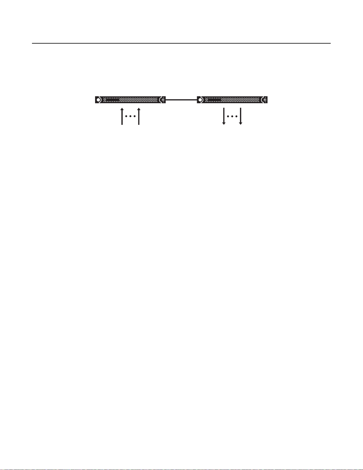
The FT8332 transmitter and FR8332 receiver provide the ability to transmit up to 32 composite video channels over one optical fiber (refer to
Figure 1).
TRANSMITTER
ONE FIBER
32 VIDEO INPUTS
RECEIVER
32 VIDEO OUTPUTS
Figure 1. Thirty-Two Channel Video FT8332 Transmitter and FR8332 Receiver
Features of the FT8332/FR8332 fiber optic transmission system include the following:
• 8-bit digitally encoded video for high-qua lity multichannel video transmission over a single fiber
• Coarse Wavelength Division Multiplexing (CWDM) technology, which allows multiple wavelengths to be transmitted in a single fiber
• Multimode fiber support for distances up to 1 km (0.6 mi)
• Single-mode fiber support for distances up to 26 km (16.1 mi)
• Exceeds all requirements for the RS-250C Medium-Haul Transmission specification
• Compatible with NTSC, PAL, and SECA M video standards
• No performance adjustments required
• 12 VDC or 24 VAC power supply
• Stand-alone and rack-mountable design
• LED indicators for monitoring of video signal status, optical signal status, laser status, and operating power
• Laser diode for transmission of optical signals
NOTE: The FT8332 transmitter/FR8332 receiver is a Class 1 laser product that complies with FDA radiation performance standard 21CFR
Subchapter J and with IEC 60825-1 Edition 1.2, 2001-08 .
MODELS
The FT8332/FR8332 fiber transmitter and receiver consist of the following series of models:
Multimode Models:
FT8332MSTR
FR8332MSTR
Single-Mode Models:
FT8332SST
FR8332SST
R
R
NOTE: Conformal coated models are available upon request. Contact the factory for additional information.
OPTIONAL ACCESSORIES
The following optional accessories are availa bl e:
EPS5000-120 External rack power supply, 1 RU, dual 120 W power outputs
WM5300
C2652M (1/08) 5
Thirty-two channel fiber optic video transmitter; multimode, ST connector
Thirty-two channel fiber optic video receiver; multimode, ST connector
Thirty-two channel fiber optic video transmitter; single-mode, ST connector
Thirty-two channel fiber optic video receiver; single-mode, ST connector
Wall mount kit
Page 6

FRONT PANEL
The front panel of the FT8332/FR8332 unit provides a removable bezel. Figure 2 illustrates the front of the unit with the bezel attached. Figure3
illustrates the front of the unit with the bezel removed.
NOTE: The Contact Closure Activation and Data Activity LEDs shown in Figure 3 are not used.
ì Power LED: Lights the Pelco badge blue to indicate that power is being applied to the unit.
NOTE: When the bezel is removed from the front panel, the Power LED does not light to indicate that power is being applied to the unit.
î Keylock: Locks/unlocks the front bezel.
ï LED Activation Switch: Lights the front-panel Optical Link and Video Present LEDs as appropriate when the bezel is removed.
NOTE: When the bezel is attached to the front panel, the Optical Link and Video Present LEDs do not light.
ñ TX Optical Link LEDs 1-4: (Applicable to FT8332 transmitter only) Light to indicate laser status. Green indicates that the laser is operating
properly. Flashing red indicates that the laser has shut down.
NOTE: The TX Optical Link LEDs operate independently of one another. TX Optical Link LED1 indicates the laser status of channels 1-8.
TX Optical Link LED 2 indicates the laser status of channels 9-16. TX Optical Link LED 3 indicates the laser status of channels 17-24. TX Optical
Link LED 4 indicates the laser status of channels 25-32.
ó RX Optical Link LEDs 1-4: (Applicable to FR8332 receiver only) Light to indicate optical signal status. Green indicates that the optical signal is
being received. Red indicates that the optical signal is not being received.
NOTE: The RX Optical Link LEDs operate independently of one another. RX Optical Link LED 1 indi cates the optical signal status of channels 1-8.
RX Optical Link LED 2 indicates the optical signal status of channels 9-16. RX Optical Link LED 3 indicates the optical signal status of
channels 17-24. RX Optical Link LED 4 indicates the optical signal status of channels 25-32.
r Contact Closure Activation LEDs: Not used.
s Data Activity LEDs: Not used.
t Video Present LEDs 1-32: Light green on a per-channel basis to indicate that the incoming video signal is present on the channel. Light red on
a per-channel basis to indicate that the incoming video signal is not present on the channel (video loss).
Figure 2. Front Panel of FT8332/FR8332 Unit with Bezel
Figure 3. Front Panel of F T8332/FR8332 Unit Without Bezel
For troubleshooting information relating to the fro nt-panel LEDs, refer to Troubleshooting on page 15.
6 C2652M (1/08)
Page 7

REAR PANEL
Figure 4 illustrates the rear panel of the FT8332/FR8332 unit.
ì Video Connectors 1-32: BNC connectors that provide 75-ohm analog video input (FT8332)/output (FR8332).
î Fiber Optic Connector: An ST multimode or single-mode connector.
ï Auxiliary Relay Output Connector: A 3-pin header that provides a relay output to external equipment if an optical signal or laser fault
occurs.
ñ Stand-Alone Power Connector: A 5-mm barrel connector for power connection of stand-alone unit. Accepts electrical power from an
external 12 VDC power supply (provided) or from a 24 VAC power supply.
ó Rack Power Connector: A 6-pin connector that accepts electrical power from an EIA rack-mounted power supply such as the Pelco 12 VDC
EPS5000-120 power supply.
For additional information about rear-panel connections, refer to Installation on page 8.
Figure 4. Rear Panel of FT8332 Transmitter/FR8332 Receiver
C2652M (1/08) 7
Page 8

Installation
PACKAGE CONTENTS
The following items are supplied:
FT8332 transmitter or FR8332 receiver
1
Accessory pack:
1
1 Screw terminal, 3-pin (for relay)
1 Regulated switching power supply, 90-264 VAC, 47-63 Hz input, 12 VDC (66 W) output
3 Power cords (North American, U.K., and European)
2 Front bezel keys
Rack mount kit (included with accessory pack):
1
2 Chassis mounting brackets with thumbscrews
6 Screws, 6-32 x 0.25-inch, Phillips flat head (three for each bracket)
2 Adjustable support rail sets (each set includes one front-mount rail and one rear-mount rail)
6 Screws, 8-32 x 0.375-inch, Phillips truss head (three for each support rail)
4 Screws, 10-32 x 0.5-inch, Phillips flat head (two for each front rail)
4 Screws, 10-32 x 0.5-inch, Phillips pan head (two for each rear rail)
10 Cage nuts, 10-32
FT8332/FR8332 Fiber Transmitter and Receiver Installation manual
1
Refer to Figure5, Figure 6, and Figure 7 for illustrations of the package contents.
SHIPPING BOX
FT8332/FR8332
ACCESSORY PACK
Figure 5. Major Package Components
INSTALLATION MANUAL
8 C2652M (1/08)
Page 9

ACCESSORY PACK
FRONT BEZEL KEY
2 EA.
RACK MOUNT KIT
USA STANDARDT
POWER CORD
(110 VAC)
1 EA.
RACK MOUNT KIT
SHOWN ACTUAL SIZE
UK
STANDARD POWER
CORD (250 VAC)
1 EA.
EUROPEAN
STANDARD POWER
CORD (220 VAC)
1 EA.
Figure 6. Accessory Pack
REAR MOUNT RAIL
2 EA.
POWER SUPPLY
1 EA.
FRONT MOUNT RAIL
2 EA.
3-PIN SCREW
TERMINAL
1 EA.
CHASSIS MOUNTING
BRACKETS
PHILLIPS FLAT
HEAD SCREW,
6-32 X 0.25-INCH
6 EA.
PHILLIPS TRUSS
HEAD SCREW,
8-32 X 0.375-INCH
6 EA.
PHILLIPS FLAT
HEAD SCREW,
10-32 X 0.5-INCH
4 EA.
PHILLIPS PAN
HEAD SCREW,
10-32 X 0.5-INCH
4 EA.
CAGE NUT,
10-32
10 EA.
Figure 7. Rack Mount Kit
C2652M (1/08) 9
Page 10

MOUNTING THE TRANSMITTER/RECEIVER
The FT8332 transmitter/FR8332 receiver can be mounted into a rack (refer to Mounting the Transmitter/Receiver into a Rack) or can be used as a
stand-alone unit. As a stand-alone un it, the transmitter/receiver can be placed on a desktop or can be mounted to a wall (refer to Mounting the
Transmitter/Receiver to a Wall on page 13).
MOUNTING THE TRANSMITTER/RECEIVER INTO A RACK
The FT8332 transmitter/FR8332 receiver can mount into an industry-standard 19-inch (48 cm) equipment rack. The rack must meet the following
requirements:
• EIA-310-D compliant
• Rack column depth: 24 to 30 inches (61 to 76 cm)
• Column-mounting hole provisions: 10-32 UNF-2B threaded holes or square window holes on front columns
• Door systems are acceptable. Front doors must have at lea s t 2 inches (5.1 cm) between the front bezel of the transmitter/receiver and the
inside of the door. Rear doors may only be used on rack columns that are more than 26 inches (66 cm) deep
The transmitter/receiver occupies one ra ck unit (1.75 inches or 4.5 cm) of vertical rack space.
WARNINGS:
• Secure the front and rear screws to the support rails.
• Make sure that the FT8332 transmitter/FR8332 receiver is level.
• Slots and openings in the cabinet provide ventilation to prevent the unit from overheating. Do not block those openings. Never place
the unit near or over a radiator or heat register. When placing the unit in a rack, be sure to provide proper ventilation. Allow at least
one rack unit (1.75 inches or 4.44 cm) of spacing between units.
To install the transmitter/receiver into a rack, do the following:
NOTE: The hardware necessary to mount the transmitter/receiver into a rack is supplied with the unit (refer to Figure7).
1. Attach one chassis mounting bracket to each side of the unit using three 6-32 x 0.25-inch Phillips flat head screws for each bracket (refer to
Figure 8).
FT8332/FR8332
ATTA CH
BRACKETS
(3) SCREWS
6-32 X 0.25-INCH
PHILLIPS FLAT HEAD
Figure 8. Attaching Chassis Mounting Brackets
10 C2652M (1/08)
Page 11

2. Mount one front-mount support rail with one rear-mount support rail back-to-back, and attach the rails using three 8-32 x 0.375-inch Phillips
75
truss head screws (refer to Figure 9). Leave the screws loose until the support rails are attached to the rack in step 7.
(3) SCREWS, 8-32 X 0.3
PHILLIPS TRUSS HEAD
Figure 9. Assembling a Support Rail
3. Repeat step 2 for the other set of front-mo unt and rear-mount support rails.
4. If you are installing the unit into a square-hold rack, continue with this step; otherwise, skip this step and proceed to step 5. Insert 10 cage
nuts into the square-hole rack (refer to Figure10). Align the top a nd botto m cage nu ts on the front r acks with the top and bo tt om cage nuts
on the rear racks.
CAGE NUT
FRONT-MOUNT RAIL
CAGE NUT
ALIGN
ALIGN
REAR-MOUNT RAIL
Figure 10. Inserting Cage Nuts
5. Attach one support rail assembly to the equipment rack in the desired location as follows (refer to Figure 11):
NOTE: The support rail assemblies are identical and may be used on either the right or left side of the rack.
a. Position the ear of the front-mount rail against the front of the equipment rack, and align the top and bottom holes in the ear of the rail
with the threaded holes (or cage nuts) in the rack.
b. Using two 10-32 x 0.5-inch Phillips flat head screws, attach the ear of the rail to the front of the rack. Insert the screws from the
outside of the rack, pointing toward the back of the rack.
c. Adjust the rails to the correct depth of the equipment rack by sliding the rear-mount rail to the back of the equipment rack.
C2652M (1/08) 11
Page 12

d. Position the ear of the rear-mount rail against the rear exterior of the equipment rack, and align the top and bottom holes in the ear of
REAR-MOUNT RAIL
the rail with the threaded holes (or cage nuts) in the equipment rack.
e. Using two 10-32 x 0.5-inch Phillips pan head screws, attach the ear of the rail to the rear of the rack. Insert the screws from the
outside of the rack, pointing toward the front of the rack (refer to Figure 11).
RACK FRONT RACK REAR
(2) SCREWS,
10-32 X 0.5-INCH
PHILLIPS FLAT HEAD
FRONT-MOUNT RAIL
(2) SCREWS,
10-32 X 0.5-INCH
PHILLIPS PAN HEAD
Figure 11. Attaching Support Rails
6. Repeat step 5 for the second support rail assembly.
7. Tighten the 8-32 x 0.375-inch Phillips truss head screws that were attached to the front- and rear-mount rails in steps 2 and 3.
8. Place the unit onto the support rails by sliding th e ch assis bra cket s on to the rails (re fer to Fig ure12). The unit should slide in and out of the
rack easily.
WARNING: When sliding the unit out of the rack, be careful not to let the unit fall out of the rack.
Figure 12. Mounting the Transmitter/Receiver into a Rack
12 C2652M (1/08)
Page 13

9. After the unit is in place, tighten the two thumbscrews to secure the unit to the rack (refer t o Fig ure 13).
THUMBSCREW
Figure 13. Tightening the Thumbscrews
MOUNTING THE TRANSMITTER/RECEIVER TO A WALL
The FT8332 transmitter/FR8332 receiver can be mounted to a wall using the WM5300 wall mount kit. The WM5300 wall mount kit provides three
slots, allowing a maximum of three FT8332/FR8332 units to be mounted to a wall. For detailed information, refer to the WM5 300 W al l Mount Kit
Installation manual.
C2652M (1/08) 13
Page 14

CONNECTIONS
N
Connections to the FT8332 transmitter/FR8332 receiver are made on the rear panel of the unit (refer to Figure 14).
COAXIAL CABLES,
CHANNELS 1-8
COAXIAL CABLES,
CHANNELS 9-16
COAXIAL CABLES,
CHANNELS 17-24
COAXIAL CABLES,
CHANNELS 25-32
FIBER OPTIC CABLE
RELAY WIRING
(REFER TO TABLE A)
POWER CONNECTIO
FOR EPS5000-120
POWER SUPPLY
POWER CONNECTION
FOR STAND-ALONE
UNIT
Figure 14. FT8332 Transmitter/FR8332 Receiver Connections
As illustrated in Figure 14, connections to the transmitter/receiver consist of the following:
• Up to 32 video input connections (transmitter only)
• Up to 32 video output connections (receiver only)
• Fiber connection
• Relay connection. Table A lists relay pin assignments.
Table A. Relay Pin Assignments
Pin Number Relay Wiring
1
2
3
Common (C)
Normally Closed (NC)
Normally Open (NO)
• Power connection
NOTES:
– A 12 VDC or 24 VAC power supply can be used to power the transmitter/receiver when used as a stand-alone unit. A 12 VDC power
supply is provided. If a 24 VAC power supply is used, the power supply must be a Listed Direct Plug-In Power Unit marked as Class 2
and rated as 24 VAC, 1.5 A (minimum output).
– A 12 VDC EPS5000-120 power supply is used when the unit is mounted into a standard 19-inch EIA rack. Up to two transmitters/
receivers can connect to the EPS5000-120 power supp ly using the two power cables provided with the power supply. Refer to the
EPS5000-120 External Power Supply Installation manual for additional information.
– In extreme temperature conditions, it is recommen ded that an industrial-rated outdoor power supply be used.
14 C2652M (1/08)
Page 15

Troubleshooting
LED indicators on the front of the FT8332 transmitter/FR8332 receiver allow you to monitor operating power, video signal status, optical signal
status, and laser status. To view the indicators on the front of the transmitter/receiver, remove the bezel from the unit (refer to Removing the
Bezel). To troubleshoot the front-panel indicators, refer to Troubleshooting Front-Panel Indicators.
REMOVING THE BEZEL
To remove the bezel from the front of the transmitter/receiver, do the following:
1. Using one of the supplied keys, unlock the bezel.
2. To detach the bezel from the unit, pull the right side of the bezel toward you—be careful not to drop the bezel (refer to Figure15).
Figure 15. Removing the Bezel
To reattach the bezel, align the bezel with the unit and push the bezel inward until it snaps into place. Lock the bezel.
TROUBLESHOOTING FRONT-PANEL INDICATORS
TableB provides information about the front-panel indicators and associated troubleshooting guidelines..
Table B. Troubleshooting Front-Panel Indicators
Indicator Color Meaning Possible Cause Corrective Action
Power LED (Pelco badge)
Not lit Power is not being applied
Red on
transmitter
Red on receiver Incoming video signal is not
to the unit.
Incoming video signal is not
present on the channel
(video loss).
present on the channel
(video loss).
Power connection is faulty. Check power connection.
Power supply has failed. Replace power supply.
Loss of power occurs due to tripped
circuit breakers, blown fuses, or faulty
electrical service.
Video Present LED
Power is not being applied to the video
source.
Video source is not connected to the
transmitter.
Coaxial cable is defective. Replace cable.
Optical signal is not being received
from the transmitter. RX Optical Link
Loss LED is also red.
Power is not being applied to the video
source.
Video source is not connected to the
transmitter.
Coaxial cable connected to the
transmitter is defective.
Check circuit breakers, fuses, or
electrical service as necessary.
Check power connection to the video
source.
Check BNC connections.
Refer to RX Optical Link Loss on
page 16.
Check power connection to the video
source.
Check BNC connections.
Replace cable.
C2652M (1/08) 15
Page 16

Table B. Troubleshooting Front-Panel Indicators (Continued)
Indicator Color Meaning Possible Cause Corrective Action
TX Optical Link Loss
Flashing red Laser has shut down. Transmitter is operating in extreme
environmental conditions; for example,
operating temperature is below or
above recommended range (refer to
Specifications on page 17).
Laser has reached end of life. Cycle the power. If problem persists,
Ensure that transmitter operates
according to recommended operating
conditions, and then cycle the power.
If problem persists, contact
Product Support at 1-800-289-9100 or
1-559-292-1981.
contact Product Support at
1-800-289-9100 or 1-559-292-1981.
RX Optical Link Loss
Red The optical signal is not
being received from the
transmitter.
Power is not being applied to the
transmitter.
Fiber optic cable is not connected. Check fiber optic connections.
Fiber optic cable connectors are dirty
or are damaged.
Fiber optic cable is defective. Replace cable.
Optical dB losses in the fiber optic
installation exceed the optical power
budget specification (refer to
Specifications on page 17).
Optical dB losses in the fiber optic
installation meet the optical power
budget specification (refer to
Specifications on page 17); however,
the receiver may be defective.
Check power connections. Replace
power supply if necessary.
Clean, polish, or replace fiber optic
cable connectors as necessary.
Check for problems with the fiber
optic installation, for example,
excessive dB losses in connectors,
splices, patch panels, cables,
and so on.
Contact Product Support at
1-800-289-9100 or 1-559-292-1981.
16 C2652M (1/08)
Page 17

Specifications
VIDEO
Number of Channels 32
Modulation Type Pulse code modulation, 8-bit resolution
Video Input (FT8332)/
Video Output (FR8332) 1.0 Vp-p, 75 ohms; NTSC, PAL, and SECAM
Bandwidth 6.5 MHz
Gain Unity
Crosstalk -50 dB typical at 3.58 MHz
Differential Gain <1%
Differential Phase <1.2°
Tilt <1%
Signal-to-Noise Ratio >60 dB (CCIR weighted)
RELAY
Relay Output 1 A at 30 VDC
GENERAL
Operating Temperature -40° to 167°F (-40° to 75°C)
Input Power Requirements 12 VDC or 24 VAC, 1.5 A
LED Indicators Power
Dimensions 16.7” D x 17.0” W x 1.7” H
Unit Weight 11.4 lb (5.17 kg)
Choice of normally open or normally closed
Video Present (per channel)
TX Optical Link Loss (per set of 8 video channels)
RX Optical Link Loss (per set of 8 video channels)
(42.4 x 43.2 x 4.3 cm)
MECHANICAL
Connectors
Video BNC (per channel)
Stand-Alone Power 5-mm barrel connector
Rack Power 6-pin connector
Fiber Optic ST for multimode and single-mode fiber
Auxiliary Relay Output 3-pin header
Construction Steel cabinet
Finish Bezel: gray metallic with black end caps
Chassis: black matte finish
C2652M (1/08) 17
Page 18

OPTICAL POWER BUDGET AND TRANSMISSION DISTANCE
Model Number
Compatible
Receiver
Wavelength
Optical
Power
Budget
Multimode (62.5/125 µm)
FT8332MSTR FR8332MSTR
1350 nm
18 dB*
†
1325 nm
1300 nm
1275 nm
Single-Mode (9/125 µm)
FT8332SSTR FR8332SSTR
1350 nm
18 dB* 26 km (16.1 mi)
1325 nm
1300 nm
1275 nm
*Optical power budget is 15 dB when operating temperature range is -40° to 0°C.
†
When using 50/125 µm multimode fiber, subtract 3 dB from the optical power budget.
‡
Maximum transmission distance is limited by fiber bandwidth.
§
Maximum transmission distance is based on attenuation of 0.5 dB/km plus a 5 dB buffer for connector and splice losses.
NOTE: For models with higher optical power budgets, contact the factory .
Maximum
Transmission
DistanceTransmitter
1 km (0.6 mi)
‡
§
18 C2652M (1/08)
Page 19

PRODUCT WARRANTY AND RETURN INFORMATION
WARRANTY
Pelco will repair or replace, without charge, any merchandise proved defective in
material or workmanship for a period of one year after the date of shipment.
Exceptions to this warranty are as noted below:
• Five years on fiber optic products and TW3000 Series unshielded twisted pair
(UTP) transmission products.
• Three years on Spectra
• Three years on Genex
• Three years on DX Series digital video recorders, DVR5100 Series digital video
recorders, DigitalSENTRY
recorders, NVR300 Series network video recorders, and Endura
distributed network-based video products.
• Three years on Camclosure
the CC3701H-2, CC3701H-2X, CC3751H-2, CC3651H-2X, MC3651H-2, and
MC3651H-2X camera models, which have a five-year warranty.
• Three years on PMCL200/300/400 Series LCD monitors.
• Two years on standard motorized or fixed focal length lenses.
• Two years on Legacy
Series fixed dome products.
• Two years on Spectra III
including when used in continuous motion applications.
• Two years on Esprit and WW5700 Series window wiper (excluding wiper
blades).
• Two years (except lamp and color wheel) on Digital Light Processing (DLP
displays. The lamp and color wheel will be covered for a period of 90 days. The
air filter is not covered under warranty.
• Two years on Intelli-M
• One year (except video heads) on video cassette recorders (VCRs). Video heads
will be covered for a period of six months.
• Six months on all pan and tilts, scanners, or preset lenses used in continuous
motion applications (preset scan, tour, and auto scan modes).
Pelco will warrant all replacement parts and repairs for 90 days from the date of
Pelco shipment. All goods requiring warranty repair shall be sent freight prepaid
to a Pelco designated location. Repairs made necessary by reason of misuse,
alteration, normal wear, or accident are not covered under this warranty.
®
IV products.
®
Series products (multiplexers, server, and keyboard).
®
Series hardware products, DVX Series digital video
®
and Pelco-branded fixed camera models, except
®
, CM6700/CM6800/CM9700 Series matrix, and DF5/DF8
™
, Spectra Mini, Esprit®, ExSite®, and PS20 scanners,
®
eIDC controllers.
®
Series
Pelco assumes no risk and shall be subject to no liability for damages or loss
resulting from the specific use or application made of the Products. Pelco’s liability
for any claim, whether based on breach of contract, negligence, infringement of
any rights of any party or product liability, relating to the Products shall not exceed
the price paid by the Dealer to Pelco for such Products. In no event will Pelco be
liable for any special, incidental, or consequential damages (including loss of use,
loss of profit, and claims of third parties) however caused, whether by the
negligence of Pelco or otherwise.
The above warranty provides the Dealer with specific legal rights. The Dealer may
also have additional rights, which are subject to variation from state to state.
If a warranty repair is required, the Dealer must contact Pelco at (800) 289-9100 or
(559) 292-1981 to obtain a Repair Authorization number (RA), and provide the
following information:
1. Model and serial number
2. Date of shipment, P.O. number, sales order number, or Pelco invoice number
3. Details of the defect or problem
If there is a dispute regarding the warranty of a product that does not fall under
the warranty conditions stated above, please include a written explanation with
the product when returned.
Method of return shipment shall be the same or equal to the method by which the
item was received by Pelco.
®
)
RETURNS
To expedite parts returned for repair or credit, please call Pelco at (800)289-9100
or (559) 292-1981 to obtain an authorization number (CA number if returned for
credit, and RA number if returned for repair) and designated return location.
All merchandise returned for credit may be subject to a 20 percent restocking and
refurbishing charge.
Goods returned for repair or credit should be clearly identified with the assigned
CA or RA number and freight should be prepaid.
The materials used in the manufacture of this document and its components are compliant to the requirements of Directive 2002/95/EC.
This equipment contains electrical or electronic components that must be recycled properly to comply with Directive 2002/96/EC of the European Union
regarding the disposal of waste electrical and electronic equipment (WEEE). Contact your local dealer for procedures for recycling this equipment.
REVISION HISTORY
Manual # Date Comments
C2652M 1/08 Original version.
Pelco, the Pelco logo, Camclosure, DigitalSENTRY, Endura, Esprit, ExSite, Genex, Intelli-M, Legacy, and Spectra are registered trademarks of Pelco, Inc. © Copyright 2008, Pelco, Inc. All rights reserved.
Spectra III is a trademark of Pelco, Inc.
DLP is a registered trademark of Texas Instruments Incorporated.
Page 20

Worldwide Headquarters
3500 Pelco Way
Clovis, California 93612 USA
USA & Canada
Tel: 800/289-9100
Fax: 800/289-9150
International
Tel: 1-559/292-1981
Fax: 1-559/348-1120
www.pelco.com
ISO9001
Australia|Canada|Finland|France|Germany|Italy|Macau|The Netherlands|Russia|Singapore
South Africa
Spain|Sweden|United Arab Emirates|United Kingdom|United States
|
 Loading...