

Page 1
C258M-A (4/00)
WM3026
Heavy-Duty Wall Mount
®
3500 Pelco Way,
Clovis, CA 93612-5699
USA
In North America & Canada:
Tel (800) 289-9100
FAX (800) 289-9150
International Customers:
Tel +1(559) 292-1981
FAX +1(559) 348-1120
www.pelco.com
IMPORTANT SAFEGUARDS AND WARNINGS
Prior to installation and use of this product, the following WARNINGS should be observed.
1. Installation and servicing should only be done by qualified service and installation personnel.
2. Installation shall be done in accordance with all local and national electrical and mechanical
codes utilizing only approved materials.
3. Use only installation methods and materials capable of supporting four times the maximum
specified load.
4. Use stainless steel hardware to fasten the mount to outdoor surf aces.
5. To prevent damage from water leakage when installing a mount outdoors on a roof or wall,
apply sealant around the bolt holes between the mount and mounting surface.
The product and/or manual may bear the follo wing marks:
This symbol indicates that there are important operating and maintenance instructions
in the literature accompanying this unit.
Please thoroughly familiarize yourself with the information in this manual prior to installation and
operation.
DESCRIPTION
The WM3026 Wall Mount will support a heavy-duty enclosure and/or pan/tilt. The wall mount will
hold loads up to 300 pounds (136.08 kg) when directly attached to any vertical load-bearing
structure.
INSTALLATION
Mounting to Surface
To install the WM3026 perform the following steps:
1. Determine the mounting location. The mounting surface should be able to support four
times the combined weight of the mount, pan/ tilt, camera and enclosure.
2. Use the flanged end of the WM3026 as a template and mark the six fastener hole positions
onto the mounting surface. Set the WM3026 mount to the side and prepare the holes for the
fasteners.
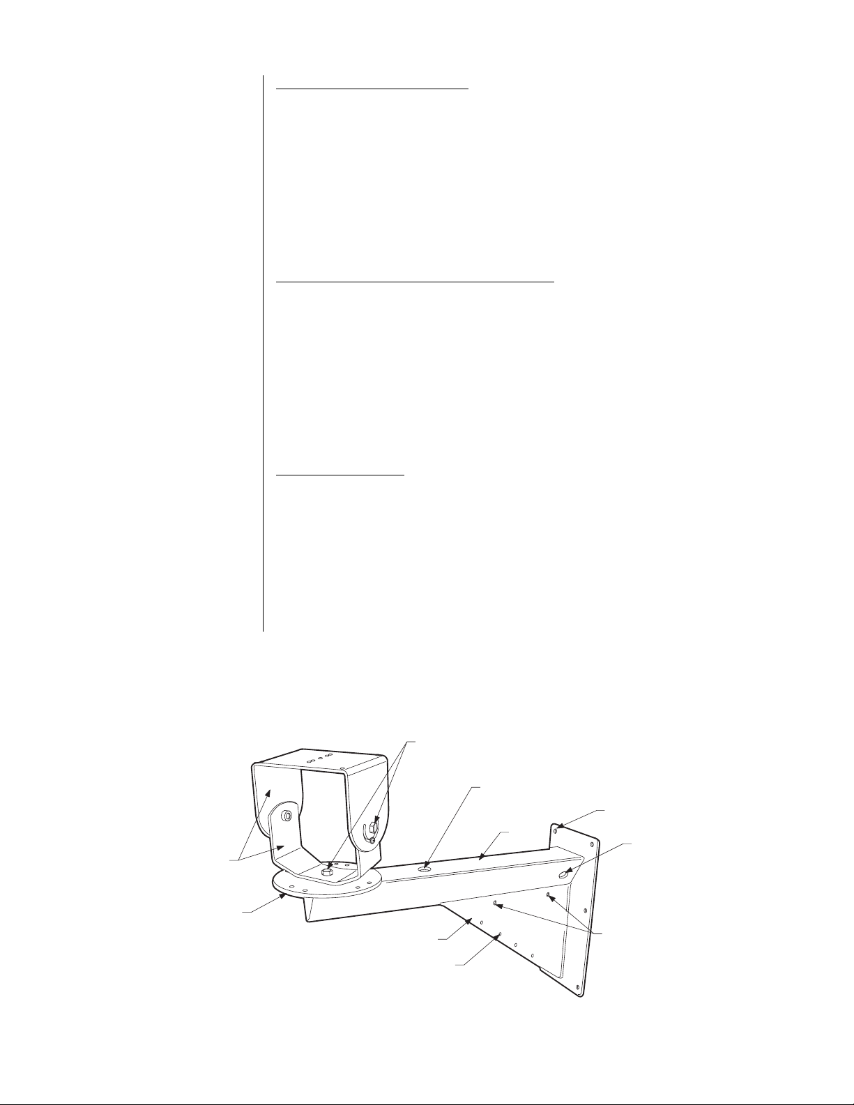
3. Use one of the following methods to prepare the wiring/cabling for power. Refer to Figure 1.
a. Thread wiring/cabling through the mount arm and exit through the top feedthrough
hole.
b. Thread the wiring/cabling through one of the 3/4-inch NPT holes on the side of the
mount arm and out the top feedthrough hole. Flexible, metal conduit connectors can
be used.
c. Bypass the mount and directly connect wiring to the camera, enclosure and/or pan/tilt.
Fold the wiring out of the way and secure.
4. Position the WM3026 mount ov er the mounting holes. Secure with a minimum of six, 3/8-inch
fasteners of appropriate length (not supplied). If you install the WM3026 outdoors, seal the
fastener holes with an appropriate sealant to prevent water damage. Apply the sealant between the mount and the mounting surface.
Page 2
Camera/Enclosure Mounting
To install the camera and/or enclosure directly to the mount, refer to Figure 1 and do the following:
1. Center the camera and/or enclosure on the tilt table.
2. Attach the camera and/or enclosure to the tilt table with 1/4-20 flat head fasteners (not provided).
3. Connect wiring/cabling to the camera and/or enclosure. Refer to the manual supplied with
the equipment for more information.
4. Loosen the hex head bolts on the top and lower brackets of the tilt table. Adjust the pan and
tilt to the desired settings. Tighten bolts and lock into place.
Pan/Tilt and Camera/Enclosure Mounting
To install the pan/tilt, camera and/or enclosure directly to the mount, refer to Figure 1 and perform the following steps:
1. Remove the tilt table from the WM3026.
2. Center the pan/tilt, camera and/or enclosure on the pan/tilt adapter. Position as needed to
align mounting holes. Secure the load to the mount using appropriate fasteners (not supplied). Refer to the manuals supplied with the equipment for more information.
3. Connect wiring /cabling to the camera, enclosure and pan/tilt. For proper installation of wiring/
cabling, refer to the manuals supplied with the equipment. Be sure to leave an adequate
loop of cables to prevent binding and/or strain where applicable.
Receiver Mounting
To mount a receiver to the gusset of the WM3026 refer to Figure 1 and do the following:
TILT TABLE ASSEMBLY
(TOP & LOWER BRACKETS)
PAN/TILT ADAPTOR
1. Line up the mounting holes on the receiver with the mounting holes on the gusset.
ing holes are six inches apart. If the receiver’s mounting holes are
not
six inches apart,
Mount-
attach it to a flat, vertical surface. Refer to the manual supplied with the receiver.
2. Attach the receiver to the gusset using 1/4-inch fasteners (not supplied) of the appropriate
length.
3. Use the four cable tie holes located on the bottom edge of the gusset (cable ties not included) and secure the wiring/cabling.
HEX HEAD BOLTS
TOP FEEDTHROUGH HOLE
FASTENER HOLE
ARM
GUSSET
CABLE TIE HOLE
3/4-NPT
THREADED
HOLE
RECEIVER MOUNTING
HOLES
Figure 1. WM3026 Heavy-Duty Wall Mount
Page 3

MAINTENANCE
Regularly scheduled maintenance is not required. If the mount has been installed outdoors, periodically check the sealant around the bolt holes for water damage.
SPECIFICATIONS
GENERAL
Construction: 0.25-inch (.63 cm) aluminum
Finish: Gray polyester powder coat
Mounting Method: Six 0.413-inch (1.05 cm) holes on rear surface
Maximum Load: 300 lb (136.08 kg)
Environment: Indoor/outdoor
Operating Range: 32° to 120°F (0° to 49°C)
Weight: 15.6 lb (7.1 kg)
Dimensions: See Figure 2
MECHANICAL
Pan Adjustment 360°
Tilt Adjustment ±90°
Cable Entry: One cable entry hole on top of mount arm. Two 3/4-inch NPT threaded holes
Suggested
Mounting Method: Secure to wall with six 3/8-inch diameter fasteners of suitable size (not sup-
(
Design and product specifications subject to change without notice.)
(one on each side); can be used for conduit. Three hole plugs provided to
cover unused holes.
plied)
20.88
(53.04)
6.5
(16.51)
6.5
(16.51)
8.31
(21.11)
5.50
(13.97)
28.75 (73.02)
5.87
(14.91)
8.50
(21.59)
8.31
(21.11)
7.00
(17.78)
NOTE: VALUES IN PARENTHESES ARE CENTIMETERS;
ALL OTHERS ARE IN INCHES.
27.31 (69.37)
6.00
(15.24)
7.00
(17.78)
16.00
(40.64)
Figure 2. WM3026 Dimension Drawing
Page 4

WARRANTY AND RETURN INFORMATION
WARRANTY
Pelco will repair or replace, without charge, any merchandise proved defective in material
or workmanship for a period of one year after the date of shipment.
Exceptions to this warranty are as noted below:
• Five years on FT/FR8000 Series fiber optic products.
• Three years on Genex® Series products (multiplexers, server, and keyboard).
• Three years on Camclosure® and fixed camera models, except the CC3701H-2,
CC3701H-2X, CC3751H-2, CC3651H-2X, MC3651H-2, and MC3651H-2X camera
models, which have a five-year warranty.
• Two years on standard motorized or fixed focal length lenses.
• Two years on Legacy®, CM6700/CM6800/CM9700 Series matrix, and DF5/DF8 Series
fixed dome products.
• Two years on Spectra®, Esprit®, ExSite™, and PS20 scanners, including when used in
continuous motion applications.
• Two years on Esprit® and WW5700 Series window wiper (excluding wiper blades).
• Eighteen months on DX Series digital video recorders, NVR300 Series network video
recorders, and Endura™ Series distributed network-based video products.months on DX
Series digital video recorders, NVR300 Series network video recorders, Endura™ Series
distributed network-based video products, and TW3000 Series twisted pair transmission
products.
• One year (except video heads) on video cassette recorders (VCRs). Video heads will be
covered for a period of six months.
• Six months on all pan and tilts, scanners or preset lenses used in continuous motion
applications (that is, preset scan, tour and auto scan modes).
Pelco will warrant all replacement parts and repairs for 90 days from the date of Pelco
shipment. All goods requiring warranty repair shall be sent freight prepaid to Pelco, Clovis,
California. Repairs made necessary by reason of misuse, alteration, normal wear, or
accident are not covered under this warranty.
Pelco assumes no risk and shall be subject to no liability for damages or loss resulting
from the specific use or application made of the Products. Pelco’s liability for any claim,
whether based on breach of contract, negligence, infringement of any rights of any party
or product liability, relating to the Products shall not exceed the price paid by the Dealer to
Pelco for such Products. In no event will Pelco be liable for any special, incidental or
consequential damages (including loss of use, loss of profit and claims of third parties)
however caused, whether by the negligence of Pelco or otherwise.
The above warranty provides the Dealer with specific legal rights. The Dealer may also
have additional rights, which are subject to variation from state to state.
REVISION HISTORY
Manual # Date Comments
C258M 7/97 Original version.
C258M-A 4/00 Updated manual to new format.
If a warranty repair is required, the Dealer must contact Pelco at (800)289-9100 or
(559) 292-1981 to obtain a Repair Authorization number (RA), and provide the following
information:
1. Model and serial number
2. Date of shipment, P.O. number, Sales Order number, or Pelco invoice number
3. Details of the defect or problem
If there is a dispute regarding the warranty of a product which does not fall under the
warranty conditions stated above, please include a written explanation with the product
when returned.
Method of return shipment shall be the same or equal to the method by which the item
was received by Pelco.
RETURNS
In order to expedite parts returned to the factory for repair or credit, please call the factory
at (800) 289-9100 or (559) 292-1981 to obtain an authorization number (CA number if
returned for credit, and RA number if returned for repair).
All merchandise returned for credit may be subject to a 20% restocking and refurbishing
charge.
Goods returned for repair or credit should be clearly identified with the assigned CA or RA
number and freight should be prepaid. Ship to the appropriate address below.
If you are located within the continental U.S., Alaska, Hawaii or Puerto Rico, send goods
to:
If you are located outside the continental U.S., Alaska, Hawaii or Puerto Rico and are
instructed to return goods to the USA, you may do one of the following:
If the goods are to be sent by a COURIER SERVICE, send the goods to:
If the goods are to be sent by a FREIGHT FORWARDER, send the goods to:
Service Department
Pelco
3500 Pelco Way
Clovis, CA 93612-5699
Pelco
3500 Pelco Way
Clovis, CA 93612-5699 USA
Pelco c/o Expeditors
473 Eccles Avenue
South San Francisco, CA 94080 USA
Phone: 650-737-1700
Fax: 650-737-0933
® Pelco, the Pelco logo, Spectra, Esprit, Genex, Legacy, and Camclosure are registered trademarks of Pelco.
™ Endura and ExSite are trademarks of Pelco. © Copyright 2000, Pelco. All rights reserved.
 Loading...