

Page 1
INSTALLATION MANUAL
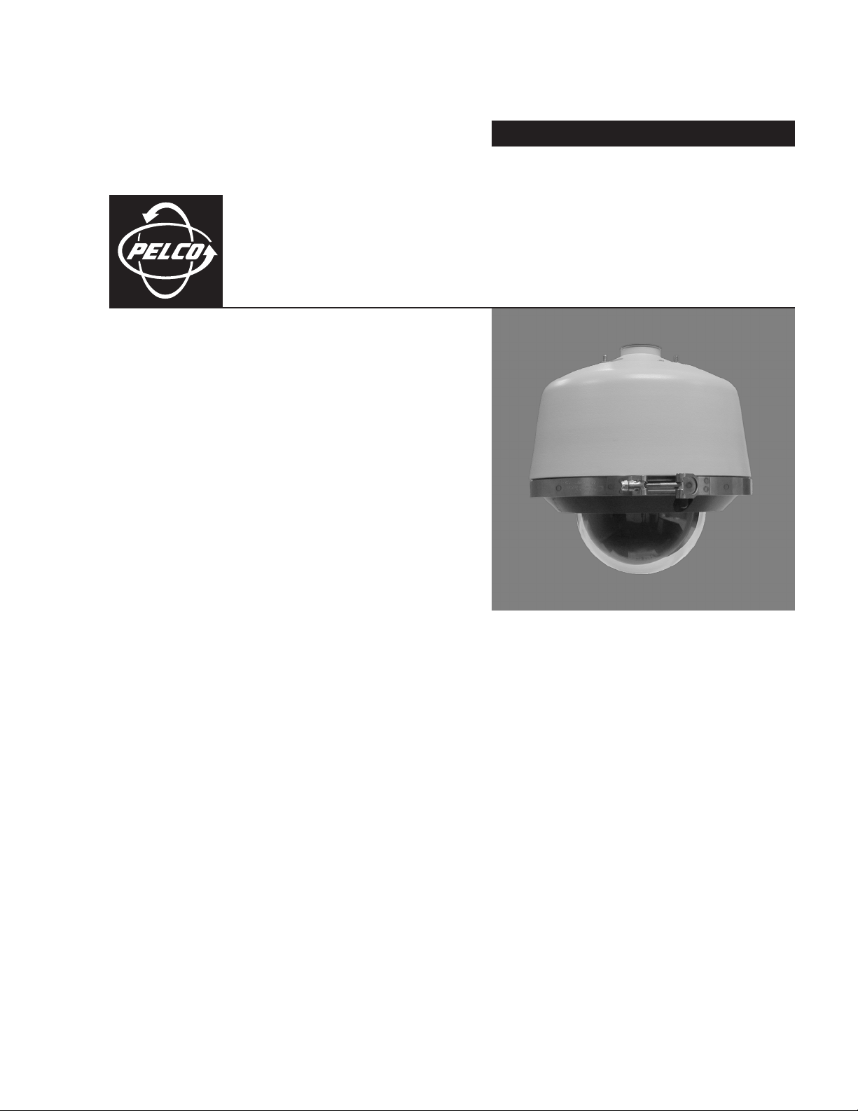
Pressurized
®
Spectra III
Fiber Optic Models
™
Series
C2485M-A (1/05)
Page 2

2 C2485M-A (1/05)
Page 3

Welcome
Thank you for purchasing Pelco’s Pressurized Spectra III
modules with an ST-type connector. Your new system provides ultimate protection of the camera optics and
electronics from moisture, corrosive gases, and airborne contaminants.
This manual is designed to be a reference tool for the installation of your system. For best results and ease of
installation, the dome system should be assembled, pressurized, and tested before installation. A Pressurized
Spectra III cable harness (supplied with the back box) is required to test and monitor the pressurized dome.
™
Series dome system with feedthrough for fiber optic
C2485M-A (1/05) 3
Page 4

Preinstallation
B
16-PIN
CONNECTOR
Install the fiber optic module: Open the hinged door to the back box
1
by pushing the tab lock towards the wall of the unit and lifting the
door open. Remove the plug from the 16-pin connector. Install the
module in the 16-pin connector. Secure the module to the circuit
board standoff using the screw and lock washer provided. Connect
the back box fiber optic connector to the mating connector on the
module. Follow all applicable instructions provided by the
manufacturer of the fiber optic module.
Loosen the V-band attached to the back box and let it hang to
2
the side.
Prepare the lower dome for installation:
3
a. Remove the O-ring from the lower dome.
b. Lightly apply O-ring lubricant (supplied) to the O-ring.
c. Reinstall the O-ring in the groove on the trim ring.
IMPORTANT: Use the supplied O-ring lubricant to ensure an air-
tight seal when installing the lower dome.
Attach the back box leash to the lower dome, and let the lower
4
dome hang to the other side of the back box.
4 C2485M-A (1/05)
Page 5

SW1 SW2 SW3
Install the dome drive:
5
a. Set the DIP switches located on the side of the dome drive.
Refer to the labels located on the top of the dome drive or to
the Quick Start Guide shipped with the dome drive.
b. Line up the blue (A) and red (B) tabs with the blue (A) and red
(B) labels.
c. Push in on the tabs. Insert one side and then the other side.
Continue pushing until both sides of the dome drive click
into place.
Install the lower dome:
6
a. Position the lower dome so that the blower duct inside the
back box is between the studs attached to the inside of the
lower dome.
b. Install the V-band around the lower dome and then tighten the
fastener of the V-band.
c. Test and check the operation of the unit before pressurizing
the dome.
Pressurize the inside of the dome with nitrogen:
7
a. Remove the cap from the Schrader valve of the dome. Place
the air chuck from the charging kit over the Schrader valve of
the dome system.
NOTE: You may use your own charging equipment or Pelco’s
EH8000RKIT recharge kit. If you are using your own equipment,
adjust the regulator for an output pressure of 12psi (83 kPa).
b. Open the tank valve of the charging kit. Fill the dome with
nitrogen for a minimum of five minutes to replace the
oxygen inside the dome with nitrogen.
c. Remove the air chuck and then replace the Schrader valve cap.
d. Refer to the Operation/Programming manual for instructions on
how to view the current readings for temperature and pressure. Record the initial temperature and pressure readings of
the dome in the space provided below:
Initial Temperature _______________
Initial Pressure _________________
IMPORTANT: Record the initial temperature and pressure readings
for future reference.
NOTE: It is normal for changes in temperature to cause dome pressure
to rise and fall.
C2485M-A (1/05) 5
Page 6

Site Installation
1
Feed a fiber optic cable (not supplied) and the supplied wiring harness into
the front of the mount and out the back of the mount. Connect the wires
as required. Refer to Tables A, B, and C for cable and wiring information.
Fasten the mount to the mounting surface. Refer to the instructions supplied with the mount.
3
2
Remove the back box mounting plate: Loosen the nuts on top of the back
box until they reach the locking material at the end of the studs, and then
turn the mounting plate clockwise and lift.
4
Thread the wiring from the mount through the mounting plate, and
then attach the mounting plate to the mount. If outdoors, apply thread
compound (provided) to the threads on the mounting plate.
Attach the connector of the wire harness to the mating connector located
on the top of the back box. Connect the fiber optic cable. Insert the studs
and nuts on top of the back box into the mounting plate, turn the back box
counterclockwise, and then tighten the three nuts.
6 C2485M-A (1/05)
Page 7

Table A. Fiber Optic Cable Types
Spectra Model Cable Type Connector
Single mode (PRS models) 9/125 µm cable ST type
Multimode (PRM models) 62.5/125 µm cable ST type
Table B. 24 VAC Wiring Distances
Wire Gauge
Total VA 20
(0.5 mm
75 37 ft
(11 m)
2
)
18
(1.0 mm
60 ft
(18 m)
2
)16(1.5 mm
95 ft
(29 m)
2
)16(2.5 mm
153 ft
(46m)
2
)
NOTE: These are the recommended maximum distances for 24 VAC appli-
cations and are calculated with a 10 percent voltage drop. (Ten percent is
generally the maximum allowable voltage drop for AC-powered devices.)
NOTE: Input power for the dome is 24 VAC only. Power consumption is
75 VA per dome.
Use a 24 VAC transformer with a minimum of 100 VA.
Table C. Configuration of Wire Harness
Pin Wire Color Function
9-Conductor Cable
A Black Alarm 1
B Red Alarm 2
C White Alarm 3
D Green Alarm 4
E Brown Alarm5
F orange Alarm 6
GYellow Alarm 7
HViolet Ground
– Blue Not Used
5-Conductor Cable
J Black Relay N.O. (Aux. 1)
K Red Relay N.C. (Aux. 1)
L Green Relay Common (Aux. 1)
M Brown Ground
N White Auxilary 2
Power Wires
a White 24 VAC (AC HI)
b Black 24 VAC (AC LO)
c Green/Yellow Earth Ground
C2485M-A (1/05) 7
Page 8

World Headquarters
3500 Pelco Way
Clovis, California 93612 USA
USA & Canada
Tel: 800/289-9100
Fax: 800/289-9150
International
Tel: 1-559/292-1981
Fax: 1-559/348-1120
www.pelco.com
ISO 9001
United States | Canada | United Kingdom | The Netherlands | Singapore | Spain | Scandinavia | France | Middle East
 Loading...