

Page 1
®
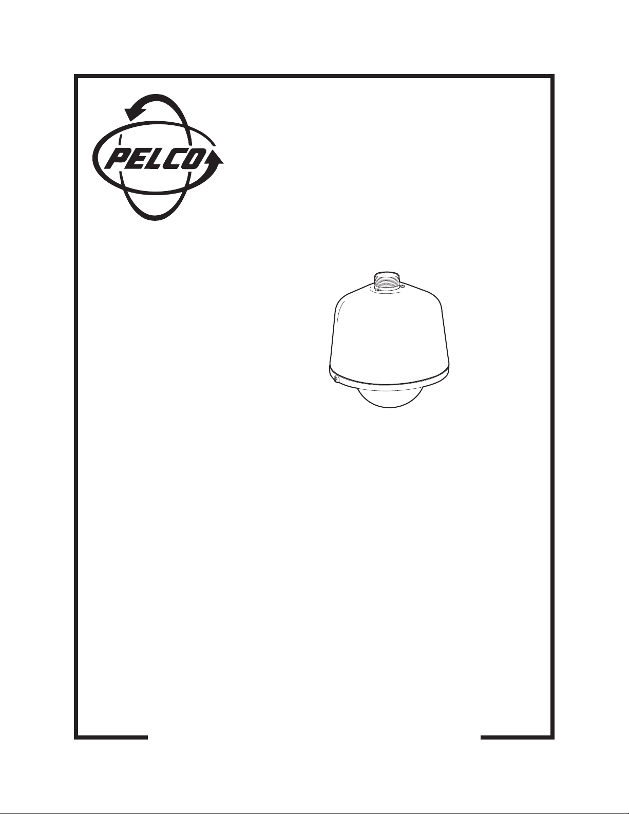
DF5HD Series
Heavy-Duty
Fixed-Mount
Dome
Installation Manual
C2432M-A (12/03)
Pelco • 3500 Pelco Way • Clovis, CA 93612-5699 USA • www.pelco.com
In North America and Canada: Tel (800) 289-9100 • FAX (800) 289-9150
International Customers: Tel +1(559) 292-1981 • FAX +1(559) 348-1120
Page 2

CONTENTS
IMPORTANT SAFEGUARDS AND WARNINGS ......................................................................................................... 3
DESCRIPTION ................................................................................................................................................................... 3
MODELS ........................................................................................................................................................................ 3
INSTALLATION IN-CEILING MODEL ........................................................................................................................... 4
PREPARE CEILING ........................................................................................................................................................4
INSTALL THE MOUNTING PLATES ............................................................................................................................. 4
INSTALL THE BACK BOX ............................................................................................................................................. 4
INSTALLATION PENDANT MODELS ........................................................................................................................... 5
MOUNT AND INSTALL THE BACK BOX....................................................................................................................... 5
CAMERA AND LENS INSTALLATION...........................................................................................................................6
LOWER DOME INSTALLATION ...................................................................................................................................... 6
IN-CEILING MODEL ...................................................................................................................................................... 6
PENDANT MODELS ...................................................................................................................................................... 6
SPECIFICATIONS .............................................................................................................................................................. 7
WARRANTY AND RETURN INFORMATION .............................................................................................................. 8
LIST OF TABLES
A Video Coaxial Cable Requirements ....................................................................................................................... 5
B 24 VAC Wiring Distances ........................................................................................................................................5
2 Pelco Installation Manual C2432M-A (12/03)
Page 3
IMPORTANT SAFEGUARDS AND WARNINGS
Prior to installation and use of this product, the following WARNINGS should be observed.
1. Installation and servicing should only be done by qualified service personnel and conform to all local codes.
2. Unless the unit is specifically marked as a NEMA Type 3, 3R, 3S, 4, 4X, 6, or 6P enclosure, it is designed for indoor use only and
it must not be installed where exposed to rain and moisture.
3. Only use replacement parts recommended by Pelco.
4. The installation method and materials should be capable of supporting four times the weight of the enclosure, pan/tilt, camera and
lens combination.
The product and/or manual may bear the following marks:
This symbol indicates that dangerous voltage
constituting a risk of electric shock is present
within this unit.
This symbol indicates that there are important
operating and maintenance instructions in the
literature accompanying this unit.
Please thoroughly familiarize yourself with the information in this manual prior to installation and operation.
CAUTION:
RISK OF ELECTRIC SHOCK.
DO NOT OPEN.
DESCRIPTION
The Heavy-duty DF5HD Series dome is perfect for fixed camera installations where structural integrity and vandalism are a priority. The
system features barrel key locks, heavy-duty construction and a thick injection-molded plastic lower dome. The in-ceiling model has a
reinforced bracket mounting system for installation in a fixed ceiling. Pendant models can be mounted to a pole or wall using the IWM
wall mount.
MODELS
DF5HD-1 In-ceiling back box with reinforced bracket-mounting system and clear dome
DF5HD-PG-1 Indoor, pendant style back box with reinforced sun shroud and clear dome
DF5HD-PG-E1 Environmental, pendant style back box with heater, fan, reinforced sun shroud and clear dome
Pelco Installation Manual C2432M-A (12/03) 3
Page 4

INSTALLATION IN-CEILING MODEL
PREPARE CEILING
00530
00531
a. Locate the center point of the mount-
ing location. Drill a hole in the ceiling
using a 3/32-inch drill.
b. Insert the compass tool into the hole.
Draw a circle on the ceiling using the
compass tool and a pencil. Cut the
circle out of the ceiling.
INSTALL THE MOUNTING PLATES
Use the eight 10-32 x 3-inch screws (supplied) and install the mounting ring and
two back mounting plates.
a. Line up the mounting ring with the
eight fastener holes.
c. Install fasteners through the mounting
ring, ceiling, and out the back mounting plate.
b. Feed one back mounting plate through
the hole in the ceiling and line up with
d. Install second back mounting plate.
four fastener holes.
INSTALL THE BACK BOX
ATTA CH SA FETY CHAIN HERE
c. Use the mounting ring as a template
and mark the hole pattern onto the
mounting surface. Prepare the holes.
S
MOUNTING
RING
SPRING CLIP
00532
CEILING
00533
8-32 X .250-INCH SCREW
00534
a. Attach the conduit fitting, lock nut, and safety chain bracket.
Install a safety chain/cable (not supplied) that will support up
to 16 pounds (7.3 kg).
c. Compress the spring clips on the back box and push it through
the hole, until the clips spring back. Tighten the screws until
you hear a clicking noise. Insert the two 8-32 x .250-inch
01237
screws to secure the back box to the mounting ring.
b. Turn the thumbscrew and open the hinged door to the back
box. Pull wiring into the back box through the conduit fitting.
Refer to Tables A and B for cable requirements and wiring
distances.
4 Pelco Installation Manual C2432M-A (12/03)
Page 5

INSTALLATION PENDANT MODELS
MOUNT AND INSTALL THE BACK BOX
NOTE: If installing outdoors make sure the installation is properly sealed to keep moisture out.
00540
a. Install the mount for the pendant dome. Refer to the instruc-
tions supplied with the mount. Bring the wiring for the dome
through the mount. Refer to Tables A and B for cable requirements and wiring distances.
b. Pull wiring from the mount into the back box.
c. Screw the back box into the mount. If outdoors, apply thread
compound (provided) to the threads on the back box.
00541
Table A. Video Coaxial Cable Requirements
Cable Type* Maximum Distance
RG59/U 750 ft (229 m)
RG6/U 1,000 ft (305 m)
RG11/U 1,500 ft (457 m)
* Minimum cable requirements:
75 ohms impedance
All-copper center conductor
All-copper braided shield with 95% braid coverage
Table B. 24 VAC Wiring Distances
The following are the recommended maximum distances for 24 VAC applications and are calculated with a 10-percent voltage drop.
(Ten percent is generally the maximum allowable voltage drop for AC-powered devices.)
EXAMPLE:
An enclosure that requires 80 vA and is installed 35 feet (10 m) from
the transformer would require a minimum wire gauge of 20 AWG.
NOTE:
Distances are calculated in feet; values in parentheses are meters.
Wire Gauge
20 18 16 14 12 10
10 283 (86) 451(137) 716 (218) 1142 (348) 1811 (551) 2880 (877)
20 141 (42) 225 (68) 358 (109) 571 (174) 905 (275) 1440 (438)
30 94 (28) 150 (45) 238 (72) 380 (115) 603 (183) 960 (292)
40 70 (21) 112 (34) 179 (54) 285 (86) 452 (137) 720 (219)
50 56 (17) 90 (27) 143 (43) 228 (69) 362 (110) 576 (175)
60 47 (14) 75 (22) 119 (36) 190 (57) 301 (91) 480 (146)
Total vA consumed
70 40 (12) 64 (19) 102 (31) 163 (49) 258 (78) 411 (125)
80 35 (10) 56 (17) 89 (27) 142 (43) 226 (68) 360 (109)
transformer to load
Maximum distance from
Pelco Installation Manual C2432M-A (12/03) 5
Page 6

D
S
CAMERA AND LENS INSTALLATION
To install the camera and lens:
1. Extend the lens to the maximum length before installing in the back box.
2. Attach the camera to the tilt table with the 1/4-20 screw and washers (supplied).
3. To ensure that the lens will not hit the lower dome:
• Place the lower dome over the back box with the camera and lens installed (do not attach dome).
• If the lens touches the lower dome, adjust the tilt table assembly.
4. Refer to the manual supplied with the camera and lens for the following information:
• How to connect power and video wiring
• How to make camera and lens adjustments
NOTE:
The torque applied to the camera mounting bracket nut should not exceed 40 pound-inches.
LOWER DOME INSTALLATION
IN-CEILING MODEL
a. Attach the lower dome trim leash to one of the 8-32 x .250-inch
screws that secure the back box to the mounting ring.
b. Insert both keys in the barrel locks. Turn keys clockwise to the un-
locked position. Keys can not be removed from lock in the unlocked
position.
TRIM LEASH
BALL STU
BALL STUD
RECEIVER
c. Align pegs (located on the mounting ring) with the peg receptacles
(located on the inside of the lower dome).
d. Place lower dome over back box. Hold and turn both keys to the
locked position.
PENDANT MODELS
00543
a. Lightly apply O-ring lubricant to the O-ring. Install the O-ring in
the groove on the trim ring of the lower dome.
Attach the back box trim leash to a retainer screw inside the
lower dome.
Environmental Model only: Plug the two-pin heater
connection in the lower dome into the mating connector in the
back box.
BARREL
LOCK
CENTER
PIN
BARREL
KEY LOCK
00494
HEATER
CONNECTOR
TRIM
LEASH
O-RING
0049500495
b. Align barrel locks in lower dome with the holes located on
each side of the back box. Push lower dome onto back box.
Press the pins of the barrel locks IN to secure the
lower dome.
6 Pelco Installation Manual C2432M-A (12/03)
Page 7

SPECIFICATIONS
ELECTRICAL
Input Voltage: 24 VAC (outdoor models only)
Input Power: 62 vA (for heater)
MECHANICAL
Construction
Back Box: Aluminum
Mounting Bracket: Steel
Lower Dome: Clear polycarbonate, 0.090 inch thick
Dimensions: See dimension drawing
GENERAL
Environment
In-Ceiling: Indoor only
Pendant: Indoor/outdoor, NEMA 4X, IP66 Rated
Operating Range
In-Ceiling: 32 to 140°F (0 to 60°C) intermittent operation; 32 to 122°F (0 to 50°C) continuous operation
Pendant
Without Heater: 32 to 140°F (0 to 60°C) absolute maximum operating temperature;
With Heater: (Assumes no wind chill factor; for detailed test conditions, contact Pelco.)
Maximum operating
temperature: 140°F (60°C) absolute maximum; 122°F (50°C) sustained maximum
Minimum operating
temperature: -60°F (-51.11°C) absolute minimum; minimal icing at -50°F (-45.56°C) sustained minimum;
Weight
Back Box
(without camera)
In-ceiling: 2.17 lb (.98 kg)
Pendant Indoor: 4.45 lb (2.02 kg)
Outdoor Pendant: 4.75 lb (2.15 kg)
Lower Dome
In-ceiling: 1.6 lb (.73 kg)
Pendant: 1.83 lb (.83 kg)
32 to 122°F (0 to 50°C) sustained maximum operating temperature
prevents icing at -40°F (-40°C) sustained minimum; de-ices. 1 inch (2.5 mm) within 3 hours after power-up
Unit
CAMERA
Maximum Camera and
Lens Size: 5.00 (L) x 2.75 (W) x 2.75 (H) (12.70 x 6.99 x 6.99 cm)
(Design and product specifications subject to change without notice.)
DUAL WALL
CONSTRUCTION
10.1
(25.65)
7.5
(19.05)
fl 6.13
(fl 15.57)
NOTE: VALUES IN PARENTHESES ARE CENTIMETERS;
ALL OTHERS ARE INCHES
9.70
(24.64)
Pelco Installation Manual C2432M-A (12/03) 7
Page 8

PRODUCT WARRANTY AND RETURN INFORMATION
WARRANTY
Pelco will repair or replace, without charge, any merchandise proved defective in material or
workmanship for a period of one year after the date of shipment.
Exceptions to this warranty are as noted below:
• Five years on FT/FR8000 Series fiber optic products.
®
• Three years on Genex
• Three years on Camclosure
CC3701H-2X, CC3751H-2, CC3651H-2X, MC3651H-2, and MC3651H-2X camera models,
which have a five-year warranty.
•Two years on standard motorized or fixed focal length lenses.
•Two years on Legacy
fixed dome products.
•Two years on Spectra
continuous motion applications.
•Two years on Esprit
• Eighteen months on DX Series digital video recorders, NVR300 Series network video
recorders, and Endura
• One year (except video heads) on video cassette recorders (VCRs). Video heads will be
covered for a period of six months.
• Six months on all pan and tilts, scanners or preset lenses used in continuous motion
applications (that is, preset scan, tour and auto scan modes).
Pelco will warrant all replacement parts and repairs for 90 days from the date of Pelco
shipment. All goods requiring warranty repair shall be sent freight prepaid to Pelco, Clovis,
California. Repairs made necessary by reason of misuse, alteration, normal wear, or accident
are not covered under this warranty.
Pelco assumes no risk and shall be subject to no liability for damages or loss resulting from
the specific use or application made of the Products. Pelco’s liability for any claim, whether
based on breach of contract, negligence, infringement of any rights of any party or product
liability, relating to the Products shall not exceed the price paid by the Dealer to Pelco for
such Products. In no event will Pelco be liable for any special, incidental or consequential
damages (including loss of use, loss of profit and claims of third parties) however caused,
whether by the negligence of Pelco or otherwise.
The above warranty provides the Dealer with specific legal rights. The Dealer may also have
additional rights, which are subject to variation from state to state.
Series products (multiplexers, server, and keyboard).
®
and fixed camera models, except the CC3701H-2,
®
, CM6700/CM6800/CM9700 Series matrix, and DF5/DF8 Series
®
, Esprit®, ExSite™, and PS20 scanners, including when used in
®
and WW5700 Series window wiper (excluding wiper blades).
™
Series distributed network-based video products.
If a warranty repair is required, the Dealer must contact Pelco at (800) 289-9100 or
(559) 292-1981 to obtain a Repair Authorization number (RA), and provide the following
information:
1. Model and serial number
2. Date of shipment, P.O. number, Sales Order number, or Pelco invoice number
3. Details of the defect or problem
If there is a dispute regarding the warranty of a product which does not fall under the
warranty conditions stated above, please include a written explanation with the product
when returned.
Method of return shipment shall be the same or equal to the method by which the item was
received by Pelco.
RETURNS
In order to expedite parts returned to the factory for repair or credit, please call the factory at
(800) 289-9100 or (559) 292-1981 to obtain an authorization number (CA number if returned
for credit, and RA number if returned for repair).
All merchandise returned for credit may be subject to a 20% restocking and refurbishing
charge.
Goods returned for repair or credit should be clearly identified with the assigned CA or RA
number and freight should be prepaid. Ship to the appropriate address below.
If you are located within the continental U.S., Alaska, Hawaii or Puerto Rico, send goods to:
Service Department
Pelco
3500 Pelco Way
Clovis, CA 93612-5699
If you are located outside the continental U.S., Alaska, Hawaii or Puerto Rico and are
instructed to return goods to the USA, you may do one of the following:
If the goods are to be sent by a COURIER SERVICE, send the goods to:
Pelco
3500 Pelco Way
Clovis, CA 93612-5699 USA
If the goods are to be sent by a FREIGHT FORWARDER, send the goods to:
Pelco c/o Expeditors
473 Eccles Avenue
South San Francisco, CA 94080 USA
Phone: 650-737-1700
Fax: 650-737-0933
Pelco, the Pelco logo, Camclosure, Esprit, Genex, Legacy, and Spectra are registered trademarks of Pelco.
Endura and ExSite are trademarks of Pelco.
Loctite is a registered trademark of Loctite Corporation.
©Copyright 2003, Pelco. All rights reserved.
REVISION HISTORY
Manual # Date Comments
C2432M 7/01 Original version.
C2432M-A 12/03 Per ECO #03-9442, changed dome material description from acrylic to clear polycarbonate.
8 Pelco Installation Manual C2432M-A (12/03)
 Loading...