

Page 1
INSTALLATION
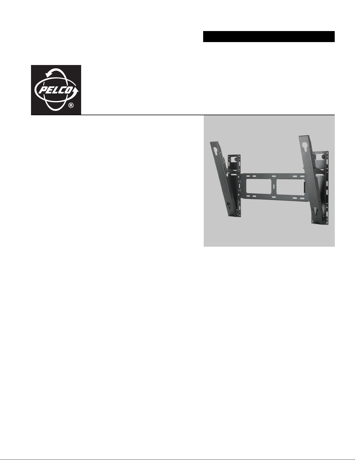
PMCP-WMT Monitor
Wall Mount
C2230M (2/07)
Page 2

Contents
Important Safety Instructions . . . . . . . . . . . . . . . . . . . . . . . . . . . . . . . . . . . . . . . . . . . . . . . . . . . . . . . . . . . . . . . . . . . . . . . . . . . . . . . . . . . . . . . . . . . . 4
Description . . . . . . . . . . . . . . . . . . . . . . . . . . . . . . . . . . . . . . . . . . . . . . . . . . . . . . . . . . . . . . . . . . . . . . . . . . . . . . . . . . . . . . . . . . . . . . . . . . . . . . . . . . 5
Model . . . . . . . . . . . . . . . . . . . . . . . . . . . . . . . . . . . . . . . . . . . . . . . . . . . . . . . . . . . . . . . . . . . . . . . . . . . . . . . . . . . . . . . . . . . . . . . . . . . . . . . . . . 5
Package Contents . . . . . . . . . . . . . . . . . . . . . . . . . . . . . . . . . . . . . . . . . . . . . . . . . . . . . . . . . . . . . . . . . . . . . . . . . . . . . . . . . . . . . . . . . . . . . . . . 5
Installation . . . . . . . . . . . . . . . . . . . . . . . . . . . . . . . . . . . . . . . . . . . . . . . . . . . . . . . . . . . . . . . . . . . . . . . . . . . . . . . . . . . . . . . . . . . . . . . . . . . . . . . . . . 6
Assembling the Wall Mount Bracket . . . . . . . . . . . . . . . . . . . . . . . . . . . . . . . . . . . . . . . . . . . . . . . . . . . . . . . . . . . . . . . . . . . . . . . . . . . . . . . . . 6
Securing the Monitor . . . . . . . . . . . . . . . . . . . . . . . . . . . . . . . . . . . . . . . . . . . . . . . . . . . . . . . . . . . . . . . . . . . . . . . . . . . . . . . . . . . . . . . . . . . . . . 8
Specifications . . . . . . . . . . . . . . . . . . . . . . . . . . . . . . . . . . . . . . . . . . . . . . . . . . . . . . . . . . . . . . . . . . . . . . . . . . . . . . . . . . . . . . . . . . . . . . . . . . . . . . . 10
2 C2230M (2/07)
Page 3

List of Illustrations
1 Tilt Wall Mount Bracket Assembly. . . . . . . . . . . . . . . . . . . . . . . . . . . . . . . . . . . . . . . . . . . . . . . . . . . . . . . . . . . . . . . . . . . . . . . . . . . . . . . . . . . . 6
2 Tilt Angle. . . . . . . . . . . . . . . . . . . . . . . . . . . . . . . . . . . . . . . . . . . . . . . . . . . . . . . . . . . . . . . . . . . . . . . . . . . . . . . . . . . . . . . . . . . . . . . . . . . . . . . . 7
3 Installing Plastic Holders . . . . . . . . . . . . . . . . . . . . . . . . . . . . . . . . . . . . . . . . . . . . . . . . . . . . . . . . . . . . . . . . . . . . . . . . . . . . . . . . . . . . . . . . . . . 8
4 Attaching Monitor to Wall . . . . . . . . . . . . . . . . . . . . . . . . . . . . . . . . . . . . . . . . . . . . . . . . . . . . . . . . . . . . . . . . . . . . . . . . . . . . . . . . . . . . . . . . . . 9
5 PMCP-WMT Dimension Drawing . . . . . . . . . . . . . . . . . . . . . . . . . . . . . . . . . . . . . . . . . . . . . . . . . . . . . . . . . . . . . . . . . . . . . . . . . . . . . . . . . . . . 10
C2230M (2/07) 3
Page 4
Important Safety Instructions
1. Read these instructions.
2. Keep these instructions.
3. Heed all warnings.
4. Follow all instructions.
5. Clean only with dry cloth.
6. Do not install near any heat sources such as radiators, heat registers, stoves, or other apparatus (including amplifiers) that produce heat.
7. Only use attachments/accessories specified by the manufacturer.
8. Installation should be done only by qualified personnel and conform to all local codes.
9. Unless this unit is specifically marked as NEMA Type 3, 3R, 3S, 4, 4X, 6, or 6P enclosure, it is designed for indoor use only and it must not be installed where exposed to rain and moisture.
10. Use only installation methods and materials capable of supporting four times the maximum specified load.
11. Only use replacement parts recommended by Pelco.
12. Do not use attachments, such as mounts, that are not recommended by Pelco. They may be hazardous.
This symbol indicates that dangerous voltage constituting a risk of electric shock is
present within this unit.
CAUTION:
This symbol indicates that there are important operating and maintenance instructions
in the literature accompanying this unit.
RISK OF ELECTRIC SHOCK.
DO NOT OPEN.
4 C2230M (2/07)
Page 5
Description
Use the PMCP-WMT mounting bracket for attaching Pelco’s PMCP642 and PMCP650 plasma monitors to walls. PMCP-WMT can be tilted at
angles from zero to 20 degrees. The PMCP-WMT can support a weight up to 220.5 lb (100 kg).
MODEL
PMCP-WMT Tilt wall mount for PMCP642, PMCP650
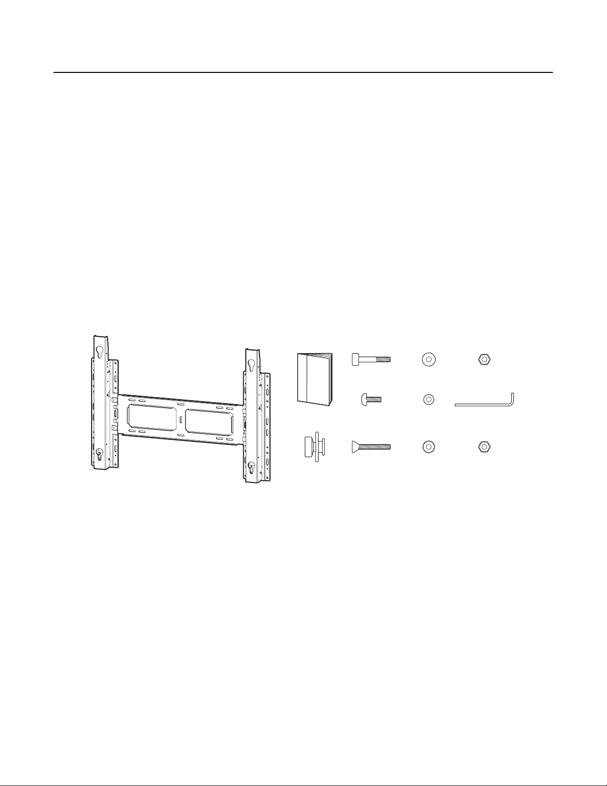
PACKAGE CONTENTS
1 Main bracket
6 Connection frame pieces
4 Plastic hangers
4 Screws (long)
6 Bolts (Allen head)
4 Screws (short)
14 Washers
10 Nuts
2Pins
1 Installation manual
WALL MOUNT BRACKET
USER MANUAL
HANGER (4 EA)
SCREW (4 EA)
SCREW (4 EA)PLASTIC
WASHER (6 EA)
WASHER (4 EA)
WASHER (4 EA)
NUT (6 EA)BOLT (6 EA)
PIN (2 EA)
NUT (4 EA)
C2230M (2/07) 5
Page 6

Installation
ASSEMBLING THE WALL MOUNT BRACKET
1. The wall mount bracket comes disassembled. Install the four short screws (included) and washers (included) in the direction shown by the arrows in Figure 1. Then tighten.
WASHER
SCREW
Figure 1. Tilt Wall Mount Bracket Assembly
6 C2230M (2/07)
Page 7

2. Use the included six bolts, washers, and nuts to assemble the tilting mechanism. (Refer to Figure 2.)
a. Install a bolt, washer, and nut where each tilt arm attaches to the bottom of the wall mount bracket.
b. Install a bolt, washer, and nut on each tilt adjustment mechanism where it attaches near the middle of the wall mount bracket.
c. Finally, install a bolt, washer, and nut where the tilt adjustment mechanism attaches to the tilt arm. Attach so the tilt arm is
completely upright (0 degrees in Figure 2) for attaching the monitor.
0°
NUT
5° 10°
BOLT
15° 20°
Figure 2. Tilt Angle
C2230M (2/07) 7
Page 8

SECURING THE MONITOR
1. Refer to Figure 2. Make sure the mounting bracket angle is set to zero.
2. Attach the mounting bracket to the wall using screws (not included) that are large enough to support the weight of the mount and the monitor and that are appropriate for the wall material. Ensure the mounting bracket is secured tightly.
WARNING: Dry wall may not be sturdy enough to support the combined weight of the monitor and the mount. Attach the mount to studs,
if possible; if not, attach plywood to the studs and the mount to the plywood. Use enough screws when attaching the mount to ensure the
monitor’s weight is evenly and adequately supported.
3. Refer to Figure 3. Remove the four screws from the back of the monitor as shown.
4. Assemble the hangers. Place a washer (included) onto each of the four screws that came with the mounting kit. Insert the screws and washers into the four plastic hangers.
5. Screw the four plastic hangers into the screw holes in the back of the monitor.
WASHER (4 EA)SCREW (4 EA)
HANGER (4 EA)
NUT (4 EA)PLASTIC
Figure 3. Installing Plastic Holders
8 C2230M (2/07)
Page 9

6. Refer to Figure 4. Lift the monitor and align the pegs of the four hangers with the grooves of the mounting bracket, then pull down on the
monitor to secure it to the wall. Check that the plastic hangers are completely secured on both the right and left sides.
WALL
MONITOR
PIN (2 EA)
BRACKET
Figure 4. Attaching Monitor to Wall
7. Insert the pins into the holes above the bottom hangers to prevent the hangers from lifting up and out of the bracket. The direction to insert them is from the outside to the inside of the bracket. This locks the hangers in place.
8. Set the tilt angle (refer to Figure 2). Be careful not to pinch your fingers when adjusting the angle.
C2230M (2/07) 9
Page 10

Specifications
GENERAL
Tilt Angle 0° to 20°
Maximum Load 220.5 lb (100 kg)
Construction Steel
Finish Black powder coating
Dimensions Refer to the dimension drawing
Unit Weight 12.1 lb (5.5 kg)
Shipping Weight 14 lb (6.3 kg)
21.0 (53.3)
16.9 (42.9)
2.3 (5.85) 2.3 (5.85)
4.32 (10.97) 4.32 (10.97)
22.39 (56.86)
29.44 (74.77)
6.77 (17.2)
20.45 (51.95)
20˚
1.54
(3.91)
NOTE: VALUE IN PARENTHESES ARE CENTIMETERS, ALL OTHERS ARE INCHES.
Figure 5. PMCP-WMT Dimension Drawing
10 C2230M (2/07)
Page 11

PRODUCT WARRANTY AND RETURN INFORMATION
WARRANTY
Pelco will repair or replace, without charge, any merchandise proved defective in material or
workmanship for a period of one year after the date of shipment.
Exceptions to this warranty are as noted below:
• Five years on fiber optic products and TW3000 Series unshielded twisted pair transmission
products.
• Three years on Spectra
• Three years on Genex
• Three years on Camclosure
CC3701H-2X, CC3751H-2, CC3651H-2X, MC3651H-2, and MC3651H-2X camera models,
which have a five-year warranty.
• Three years on PMCL200/300/400 Series LCD monitors.
• Two years on standard motorized or fixed focal length lenses.
• Two years on Legacy
dome products.
• Two years on Spectra III
continuous motion applications.
• Two years on Esprit and WW5700 Series window wiper (excluding wiper blades).
• Two years (except lamp and color wheel) on Digital Light Processing (DLP
The lamp and color wheel will be covered for a period of 90 days. The air filter is not
covered under warranty.
• Eighteen months on DX Series digital video recorders, NVR300 Series network video
recorders, and Endura
• One year (except video heads) on video cassette recorders (VCRs). Video heads will be
covered for a period of six months.
• Six months on all pan and tilts, scanners or preset lenses used in continuous motion
applications (that is, preset scan, tour and auto scan modes).
Pelco will warrant all replacement parts and repairs for 90 days from the date of Pelco
shipment. All goods requiring warranty repair shall be sent freight prepaid to Pelco, Clovis,
California. Repairs made necessary by reason of misuse, alteration, normal wear, or accident
are not covered under this warranty.
Pelco assumes no risk and shall be subject to no liability for damages or loss resulting from
the specific use or application made of the Products. Pelco’s liability for any claim, whether
based on breach of contract, negligence, infringement of any rights of any party or product liability, relating to the Products shall not exceed the price paid by the Dealer to Pelco for such
Products. In no event will Pelco be liable for any special, incidental or consequential damages
(including loss of use, loss of profit and claims of third parties) however caused, whether by
the negligence of Pelco or otherwise.
The above warranty provides the Dealer with specific legal rights. The Dealer may also have
additional rights, which are subject to variation from state to state.
®
IV products.
®
Series products (multiplexers, server, and keyboard).
®
and fixed camera models, except the CC3701H-2,
®
, CM6700/CM6800/CM9700 Series matrix, and DF5/DF8 Series fixed
™
, Esprit®, ExSite®, and PS20 scanners, including when used in
®
) displays.
™
Series distributed network-based video products.
If a warranty repair is required, the Dealer must contact Pelco at (800) 289-9100 or
(559) 292-1981 to obtain a Repair Authorization number (RA), and provide the following
information:
1. Model and serial number
2. Date of shipment, P.O. number, Sales Order number, or Pelco invoice number
3. Details of the defect or problem
If there is a dispute regarding the warranty of a product which does not fall under the
warranty conditions stated above, please include a written explanation with the product when
returned.
Method of return shipment shall be the same or equal to the method by which the item was
received by Pelco.
RETURNS
In order to expedite parts returned to the factory for repair or credit, please call the factory at
(800) 289-9100 or (559) 292-1981 to obtain an authorization number (CA number if returned for
credit, and RA number if returned for repair).
All merchandise returned for credit may be subject to a 20% restocking and refurbishing
charge.
Goods returned for repair or credit should be clearly identified with the assigned CA or RA
number and freight should be prepaid. Ship to the appropriate address below.
If you are located within the continental U.S., Alaska, Hawaii or Puerto Rico, send goods to:
Service Department
Pelco
3500 Pelco Way
Clovis, CA 93612-5699
If you are located outside the continental U.S., Alaska, Hawaii or Puerto Rico and are instructed
to return goods to the USA, you may do one of the following:
If the goods are to be sent by a COURIER SERVICE, send the goods to:
Pelco
3500 Pelco Way
Clovis, CA 93612-5699 USA
If the goods are to be sent by a FREIGHT FORWARDER, send the goods to:
Pelco c/o Expeditors
473 Eccles Avenue
South San Francisco, CA 94080 USA
Phone: 650-737-1700
Fax: 650-737-0933
The materials used in the manufacture of this document and its components are compliant to the requirements of Directive 2002/95/EC.
REVISION HISTORY
Manual # Date Comments
C2230M 2/07 Original version.
Pelco, the Pelco logo, Camclosure, Esprit, ExSite, Genex, Legacy, and Spectra are registe red trademarks of Pelco. ©Copyright 2007, Pelco. All rights reserved.
Endura, and Spectra III are trademarks of Pelco.
DLP is a registered trademark of Texas Instruments, Inc.
Page 12

Worldwide Headquarters
3500 Pelco Way
Clovis, California 93612 USA
USA & Canada
Tel: 800/289-9100
Fax: 800/289-9150
International
Tel: 1-559/292-1981
Fax: 1-559/348-1120
www.pelco.com
ISO9001
Australia|Canada|Finland|France|Germany|Italy|Macau|The Netherlands|Russia|Singapore|South Africa|Spain
Sweden
United Arab Emirates|United Kingdom|United States
|
 Loading...