

Page 1
®
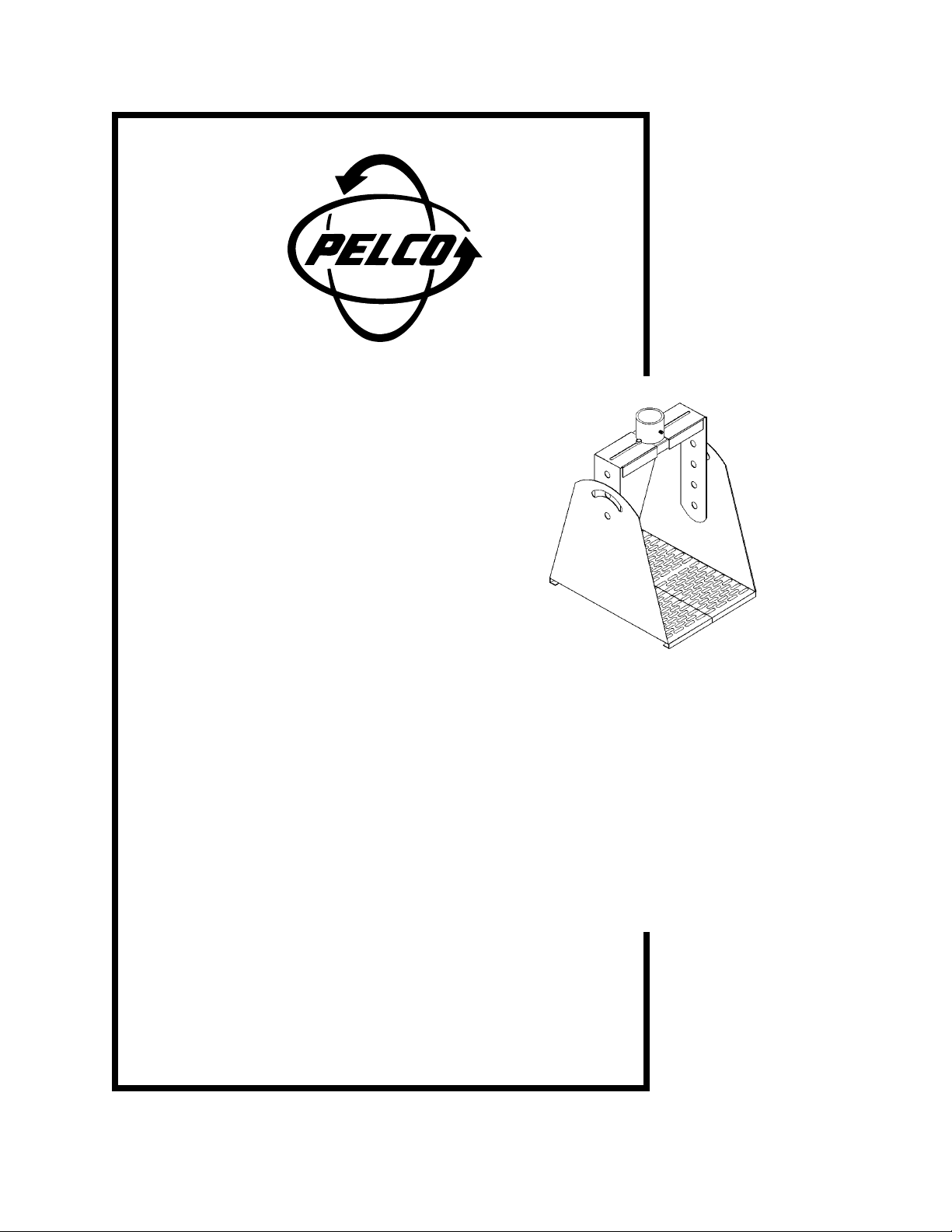
MR3050
Universal Monitor Mount
Installation/Operation Manual
C222M-A (8/95)
Pelco • 300 W. Pontiac Way, Clovis, CA 93612-5699 • USA • (800) 289-9100 or (1-559) 292-1981
FAX (800) 289-9150 or (1-559) 292-3827 • DataFax (800) 289-9108 or (1-559) 292-0435
International customers call (1-559) 292-1981 or FAX (1-559) 348-1120
Page 2

TABLE OF CONTENTS
Section Page
1.0 WARNINGS........................................................................................................................................1
2.0 SCOPE...............................................................................................................................................1
3.0 DESCRIPTION...................................................................................................................................1
3.1 RECOMMENDED MOUNTS ....................................................................................................1
4.0 SPECIFICATIONS ..............................................................................................................................2
5.0 INSTALLATION...................................................................................................................................3
5.1 MRCA/MRWA ADAPTER MOUNTING.....................................................................................3
5.2 MR3050 INST ALLA TION ..........................................................................................................3
6.0 EXPLODED ASSEMBL Y....................................................................................................................4
7.0 MECHANICAL PARTS LIST...............................................................................................................5
8.0 WARRANTY AND RETURN INFORMATION.....................................................................................6
LIST OF ILLUSTRATIONS
Figure Page
1 MR3050 Dimension Drawing ..........................................................................................................2
2 MR3050 Exploded Assembly Diagram............................................................................................4
REVISION HISTORY
Manual # Date Comments
C222M 6/94 Original version.
C222M-A 8/95 Revision A. Revised Section 7.0, Mechanical Parts List, items 4 and 13.
Updated manual to include metric equivalents.
®PELCO and the PELCO logo are registered trademarks of PELCO.
©Copyright 1995, PELCO. All rights reserved.
ii PELCO Manual C222M-A (8/95)
Page 3

INSTALLATION/OPERATION MANUAL
MR3050
UNIVERSAL MONITOR MOUNT
1.0 WARNINGS
Prior to installation and use of this product, the following
WARNINGS should be observed.
1. Installation and servicing should only be done by
Qualified Service Personnel and conform to all
Local codes.
2. Installation shall be done in accordance with all
local and national electrical and mechanical codes
utilizing only approved materials.
3. Use only installation methods and materials capable of supporting four (4) times the maximum
specified load.
4. Use stainless steel hardware to fasten the mount to
outdoor surfaces.
5. To prevent damage from water leakage when installing a mount outdoors on a roof or wall, apply
sealant around the bolt holes between the mount
and mounting surface.
Please thoroughly familiarize yourself with the information in this manual prior to installation and operation.
2.0 SCOPE
The information contained within this manual covers
the MR3050 Universal Monitor Mount.
3.0 DESCRIPTION
The MR3050 is a universal monitor mount engineered
to safely mount a monitor from either a ceiling or a
wall. This mount was designed for use in security
systems, educational institutions, churches, hospitals,
and other applications requiring flexibility in monitor
mounting and positioning.
The MR3050 is an adjustable mount designed for use
with 14-19" (35.56-48.26 cm) monitors. Two optional
adapters are available for this mount: the MRWA for
wall mounting and the MRCA for ceiling mounting.
An 8" (20.32 cm) length of 1-1/2" NPT pipe is provided
with the mount.
3.1 RECOMMENDED MOUNTS
MRWA Wall mount, uses six (6), 5/16" diameter
fasteners (not supplied)
MRCA Ceiling mount, uses four (4), 5/16" diam-
eter fasteners (not supplied)
PELCO Manual C222M-A (8/95) 1
Page 4

4.0 SPECIFICATIONS
Maximum Load: 65 lbs (29.45 kg)
Tilt Angle: Adjustable ±45°
Construction: Steel
Finish: Poly vinyl powder coat
Dimensions: See Figure 1
Weight: 17.08 lbs (7.74 kg)
Shipping Weight: 20 lbs (9.06 kg)
Figure 1. MR3050 Dimension Drawing
2 PELCO Manual C222M-A (8/95)
Page 5

5.0 INSTALLATION
5.1 MRCA/MRWA ADAPTER MOUNTING
3. Thread the 8" (20.32 cm) pipe supplied into the
ceiling/wall adapter which has already been installed.
1. Determine the mounting location. Remember to
allow for adequate clearance on all sides of the
monitor.
NOTE: When determining the mounting location, consideration must be given to the total
weight of the monitor and the mount. The
mounting surface must be adequate to support
this weight.
2. Use the adapter mount as a template to mark the
required mounting holes.
3. Using the necessary fasteners, attach the adapter
mount to the chosen surface.
5.2 MR3050 INSTALLATION
1. Determine the width the base mounting brackets
(item 1, Figure 2) must be positioned to in order to
accommodate the monitor being used. Next, attach
the two (2) bracket supports (item 13, Figure 2) to
the base mounting brackets as indicated in Figure
2.
4. Thread collar with cross bar attached onto the end
of the 8" (20.32 cm) pipe attached to the ceiling/
wall mount (already installed).
5. Slide the side brackets (item 2, Figure 2) onto cross
bar and thread on the 1/4-20 bolts. Don't tighten
bolts until all pieces are together.
6. Lift monitor with base pieces attached up to mount.
Attach side brackets to base pieces on monitor using the four (4) 3/8-16 bolts supplied.
7. Tighten set screws in upper part of collar to lock
mount and collar in place.
8. Tilt the monitor to the desired angle and tighten
bolts on each side of adjusting brackets.
9. Make all necessary electrical connections.
2. Attach the monitor to the base mounting brackets.
If the monitor has removable rubber feet, remove
the screws from the monitor feet and remove the
feet. Use the same hardware to attach the monitor
to the base mounting brackets.
PELCO Manual C222M-A (8/95) 3
Page 6

6.0 EXPLODED ASSEMBLY
An exploded assembly diagram for the MR3050 is shown in Figure 2.
Figure 2. MR3050 Exploded Assembly Diagram
4 PELCO Manual C222M-A (8/95)
Page 7

7.0 MECHANICAL PARTS LIST
Item No. Qty Description Part Number
1 2 Base, upright MR30504001COMP
2 2 Adj., side bracket MR30504003COMP
3 1 Cross bar MR30504000COMP
4 1 Collar MR30004103COMP
5 1 1/2-13 Bolt, 1.00 long ZH1/213X1.00CH
6 2 Set screw 1/4-20 ZH1/420X.250S
7 6 Hex head 1/4-20 ZH1/4-20X.500CH
8 6 Washer, flat ZH260X562X65C
9 1 Washer, flat MR30504104COMP
10 4 Bolt 3/8-16 hex head ZH3/816X.500SH
11 4 Washer, flat ZH377X880X78
12 1 Pipe nipple, 8" L x 1-1/2" NPT (not shown) MRU4207COMP
13 2 Bracket, support MR30504002COMP
14 1 Nylock nut ZH1/213NUTCHN
NOTE: Items 3, 4, 5, 9 and 14 are shipped factory assembled.
PELCO Manual C222M-A (8/95) 5
Page 8

8.0 WARRANTY AND RETURN
INFORMATION
WARRANTY
Pelco will repair or replace, without charge, any merchandise proved defective in material or workmanship
for a period of one (1) year after the date of shipment.
Exceptions to this warranty are as noted below:
• T wo (2) years on all standard motorized and fixed
focal length lenses.
• Two (2) years on Legacy®, Intercept®, CM8500/
CM9500/CM9750 Matrix, Spectra™, DF5 Series
and DF8 Fixed Dome products.
• Two (2) years on WW5700 series window wiper
(excluding wiper blades).
• Two (2) years on cameras.
• Six (6) months on all pan and tilts, scanners or preset lenses used in continuous motion applications
(e.g., preset scan, tour and auto scan modes).
Pelco will warranty all replacement parts and repairs
for 90 days from the date of Pelco shipment. All goods
requiring warranty repair shall be sent freight prepaid
to Pelco, Clovis, California. Repairs made necessary
by reason of misuse, alteration, normal wear, or accident are not covered under this warranty.
Pelco assumes no risk and shall be subject to no liability for damages or loss resulting from the specific use
or application made of the Products. Pelco’s liability
for any claim, whether based on breach of contract, negligence, infringement of any rights of any party or product liability, relating to the Products shall not exceed
the price paid by the Dealer to Pelco for such Products.
In no event will Pelco be liable for any special, incidental or consequential damages (including loss of use,
loss of profit and claims of third parties) however
caused, whether by the negligence of Pelco or otherwise.
If a warranty repair is required, the Dealer must contact Pelco at (800) 289-9100 or (559) 292-1981 to obtain a Repair Authorization number (RA), and provide
the following information:
1. Model and serial number
2. Date of shipment, P.O. number, Sales Order number, or Pelco invoice number
3. Details of the defect or problem
If there is a dispute regarding the warranty of a product
which does not fall under the warranty conditions stated
above, please include a written explanation with the
product when returned.
Ship freight prepaid to: Pelco
300 W est Pontiac Way
Clovis, CA 93612-5699
Method of return shipment shall be the same or equal
to the method by which the item was received by Pelco.
RETURNS
In order to expedite parts returned to the factory for
repair or credit, please call the factory at (800) 2899100 or (559) 292-1981 to obtain an authorization number (CA number if returned for credit, and RA number
if returned for repair). Goods returned for repair or credit
should be clearly identified with the assigned CA/RA
number and freight should be prepaid. All merchandise returned for credit may be subject to a 20% restocking and refurbishing charge.
Ship freight prepaid to: Pelco
300 W est Pontiac Way
Clovis, CA 93612-5699
The above warranty provides the Dealer with specific
legal rights. The Dealer may also have additional rights,
which are subject to variation from state to state.
6 PELCO Manual C222M-A (8/95)
 Loading...